Short answer: select an air handler, also called an air handling unit or AHU, from the air quantity, external static pressure, outdoor-air fraction, coil duty, filtration, casing, controls, and service envelope. The fan moves the air, the filters protect the occupied space and coil, and the heating or cooling coil changes air temperature and humidity. A dependable quote shows those duties at normal, minimum, and peak conditions instead of choosing a cabinet from nominal tons alone.
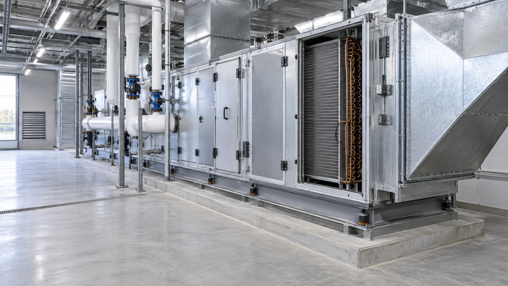
What an air handler does in a commercial HVAC system
An air handler is the section of an HVAC system that receives return and outdoor air, filters it, changes its temperature or moisture content, and sends the conditioned air into ductwork. The cabinet itself does not create cooling or heating. It works with a chiller, boiler, heat pump, direct-expansion circuit, heat recovery device, or another source of thermal energy.
That boundary matters when a project is quoted. An AHU schedule may list a cooling capacity, but the installed result also depends on airflow, entering air condition, coil fluid temperature, fan pressure, filter loading, damper position, and control sequence. A coil that is correctly rated at one airflow can carry water, condensate, or frost risk at another.
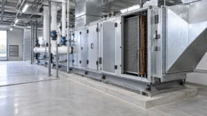
The core sections normally include a supply or plug fan, motor and drive, filters, heating or cooling coils, dampers, mixing box, drain pan, access doors, sensors, and a controls interface. Some units add humidification, heat recovery, sound attenuation, UV treatment, or a second coil. The right configuration is the smallest set of sections that satisfies the air-quality, thermal, acoustic, and maintenance requirements.
| AHU section | ما الذي يغيره | Information the buyer should confirm |
|---|---|---|
| Fan, motor, and drive | Air volume and pressure delivery | Design airflow, external static pressure, turndown, motor efficiency, speed control, sound limit |
| Filter bank | Particle removal and coil protection | Filter class, face area, initial and final pressure drop, replacement access, spare strategy |
| Heating or cooling coil | Air temperature and, for cooling coils, moisture removal | Fluid or refrigerant, entering and leaving conditions, capacity, airside and waterside pressure drop, materials |
| Dampers and mixing box | Outdoor, return, and relief-air proportion | Minimum outdoor air, leakage class, actuator torque, economizer sequence, freeze position |
| Drain pan and casing | Condensate collection and thermal boundary | Pan slope and material, insulation, vapor seal, leakage control, access, roof or indoor exposure |
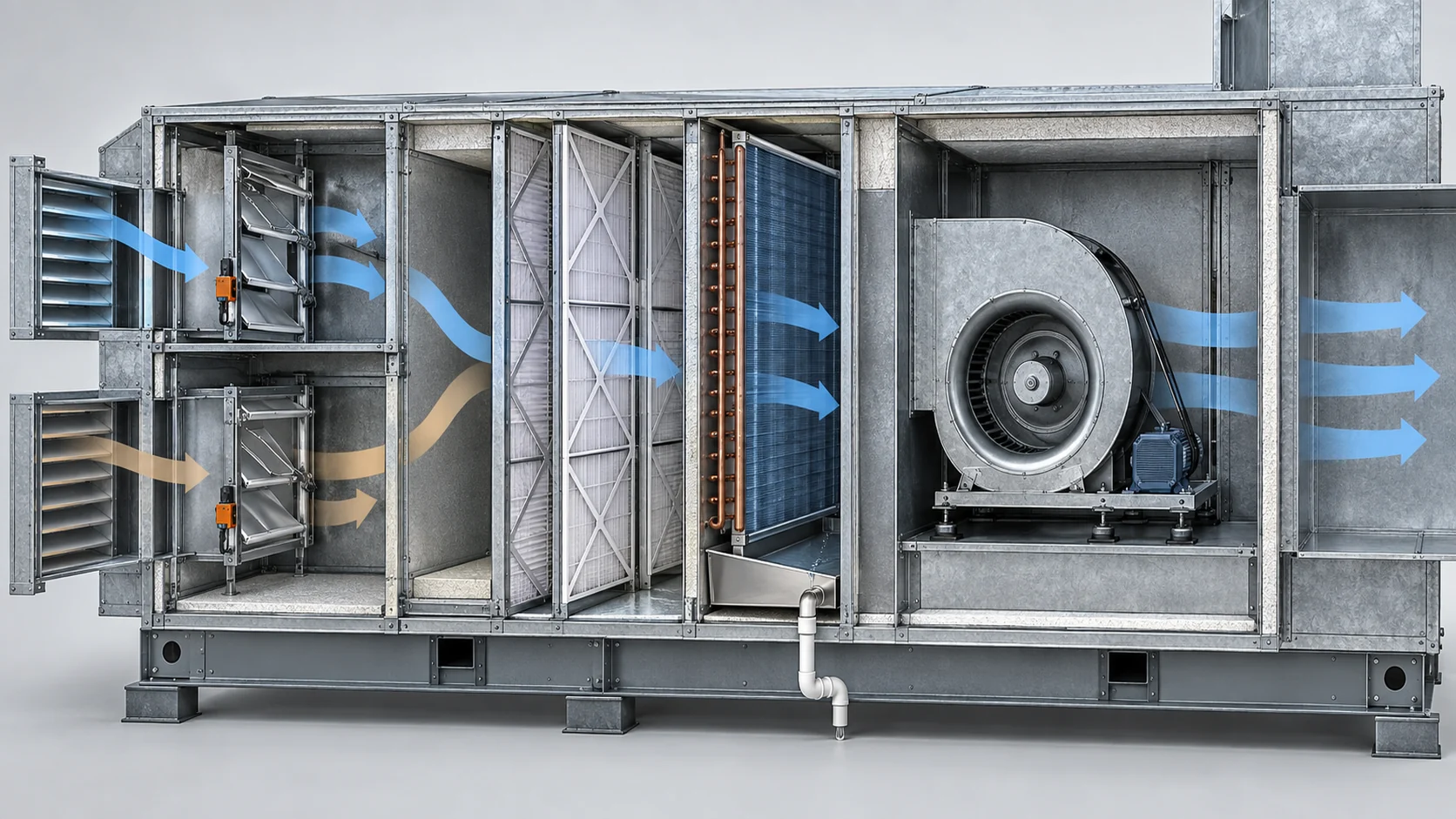
الدليل commercial air handler explanation from Trane describes the air handler as the equipment that moves, filters, heats, cools, and distributes air while working with chillers, boilers, or other HVAC equipment. Use that system boundary when deciding whether a request is for a complete AHU, a replacement coil, or a custom heat-transfer component.
Start with the airside duty, not the cabinet size
Begin with the air quantity for each operating case. Record supply airflow, return airflow, minimum outdoor air, relief air, mixed-air temperature, entering dry-bulb and wet-bulb conditions, and the leaving-air target. Add external static pressure for the duct system, filter loading, dampers, sound attenuation, terminal devices, and any future allowance. If the fan is expected to run at reduced speed, include the minimum stable airflow and pressure as well as the design point.
Face area is a practical selection variable because it affects coil pressure drop, moisture carryover, cabinet size, and filter life. A high face velocity may reduce the casing footprint but can increase airside resistance and carry droplets past a cooling coil. A low face velocity can improve moisture control but may require a wider cabinet. Ask for the rated face velocity and the pressure-drop curve rather than accepting a generic “high efficiency” description.
| Airside input | Normal case to send | لماذا يغير الاختيار |
|---|---|---|
| Air quantity | Supply, return, minimum outdoor, and relief airflow for each mode | Sets fan duty, face area, coil rows, and damper sizing |
| تكييف الهواء | Entering dry-bulb, wet-bulb or dew point, altitude, and design humidity | Sets sensible and latent coil load and condensate rate |
| Pressure budget | External static pressure plus filter, coil, damper, silencer, and terminal losses | Prevents a fan that meets flow but misses the installed pressure |
| Operating range | Minimum, normal, peak, startup, economizer, and emergency airflow | Checks turndown, control stability, freeze risk, and coil distribution |
| Acoustic and space limits | Sound target, footprint, height, door swing, lifting path, and duct orientation | Determines fan arrangement, casing dimensions, and service access |
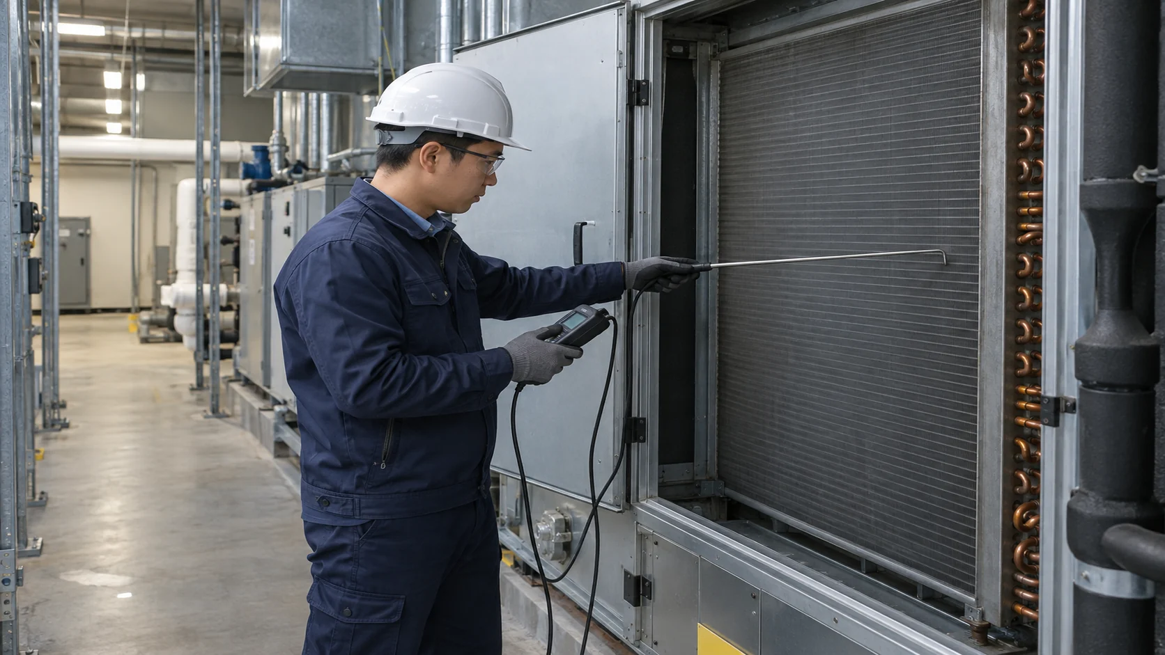
For a new building, send the design-day load calculation or a clear schedule of zones and ventilation requirements. For a replacement, measure actual airflow and static pressure when possible. Nameplate capacity alone does not reveal whether the original unit was oversized, whether filters are loaded, or whether the duct system changed after installation.
Match the coil to the heat-transfer job
The coil is the thermal heart of an air handler, but the fluid boundary decides its construction. A chilled-water coil needs water flow, entering and leaving water temperature, glycol concentration, and a maximum waterside pressure drop. A hot-water or steam coil needs a control range, condensate-drainage plan, and a non-freezing strategy. A DX coil needs refrigerant, circuiting, distributor information, superheat or subcooling assumptions, and a connection layout that suits the compressor and expansion device.
Heat recovery coils or run-around loops add another fluid circuit and a control sequence. State whether the objective is sensible recovery, latent recovery, frost avoidance, or a fixed leaving-air temperature. If an air-to-air heat exchanger is used, document the exhaust-air contaminants, leakage limit, bypass position, and cleaning access.
| حمل الملف | Selection inputs | Common failure when the input is missing |
|---|---|---|
| ماء مبرد أو جليكول | Flow, concentration, entering and leaving temperatures, design pressure, tube and fin materials | Insufficient capacity, high pump head, freeze damage, or poor low-load control |
| Hot water | Water flow, supply temperature, return target, valve authority, coil rows, and casing exposure | Hunting valve, stratified leaving air, or a coil that cannot heat at design airflow |
| Steam | Steam pressure and quality, condensate return, pitch, trap arrangement, and freeze protection | Water hammer, uneven heat release, or condensate trapped in the coil |
| Direct expansion refrigerant | Refrigerant, circuiting, mass flow, distributor, superheat, suction pressure, and oil return | Uneven circuit loading, oil logging, frost, or excessive refrigerant pressure drop |
| Heat recovery or run-around | Source and sink conditions, intermediate fluid, pump flow, bypass mode, and contamination risk | Recovery only works at one condition or creates unwanted cross-contamination |
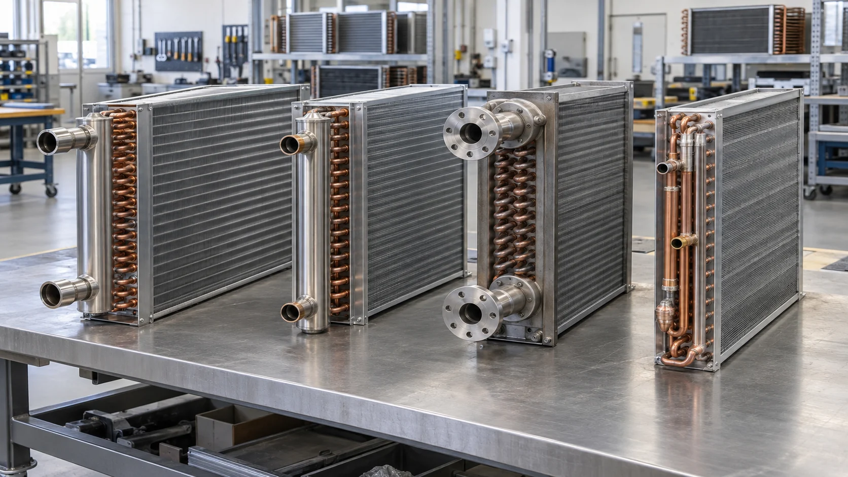
Trane’s commercial coil documentation shows that air-handler coils can be supplied for water, steam, or refrigerant and can be tailored to capacity, pressure drop, dimensions, tube diameter, fin, and casing materials. Its product page also points buyers to AHRI Standard 410 rating documentation for coil performance. Request the applicable rating method and the actual selection sheet for your project; do not treat a catalog coil label as a certified result for a different airflow or fluid.
If you need an air-side component rather than a complete air handler, compare the requirement with Domi’s ملفات التبريد التجارية و ملفات التبريد الصناعية. A coil replacement and a full AHU package have different interfaces, responsibilities, and acceptance tests.
Size face area and pressure drop together
The fan and coil must be selected as a pair. A larger coil face can reduce airside pressure drop and improve moisture control, but it increases cabinet width and cost. More coil rows may raise capacity at the same face area, but they add airside and waterside resistance and can make cleaning harder. A smaller face may fit a tight plant room while forcing a higher fan speed and more sound.
Use a simple heat balance as a first check, then let the supplier rate the coil. For sensible air cooling, the calculation must distinguish sensible load from total load because condensate removal changes the entering and leaving-air state. For water coils, the fluid-side check is Q = m × cp × ΔT; the airside result must agree with the required temperature and humidity change. Send altitude and air density assumptions so that airflow and fan pressure are not compared on incompatible bases.
Ask for a selection sheet that reports capacity, entering and leaving air, face velocity, airside pressure drop, fluid flow, fluid-side pressure drop, rows and circuits, connection size, and condensate rate where applicable. Require normal and minimum cases for variable-air-volume systems. A unit that performs well only at peak airflow may starve a terminal zone or freeze a coil during low-load operation.
The U.S. Department of Energy’s air-handling-unit design guidance also treats fan, coil, filter, pressure-drop, and control choices as a connected energy design problem. Use that principle in the schedule: every component added to the air path consumes part of the available fan pressure.
Select filters, casing, and moisture control
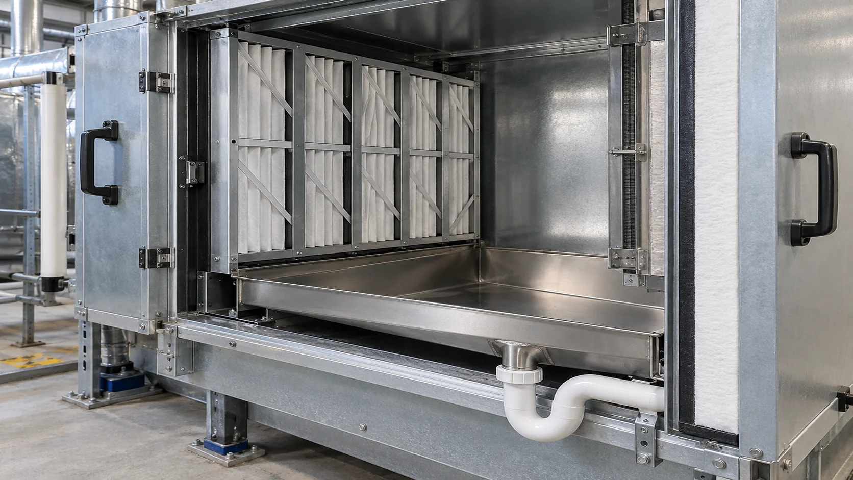
Filters are part of the fan and coil pressure budget. Specify the required filter class, face area, initial pressure drop, final pressure-drop limit, and replacement method. A high-efficiency filter with too little face area can consume the available fan pressure and reduce delivered airflow. Keep a clean-filter and loaded-filter case in the schedule.
For outdoor or humid installations, define casing construction, insulation thickness, thermal bridges, vapor sealing, leakage control, and corrosion exposure. Double-wall panels may protect the insulation and make cleaning safer, but the exact panel, fastener, and coating specification still needs to be written. For indoor units, confirm whether the casing must resist washdown, chemical exposure, or negative pressure collapse.
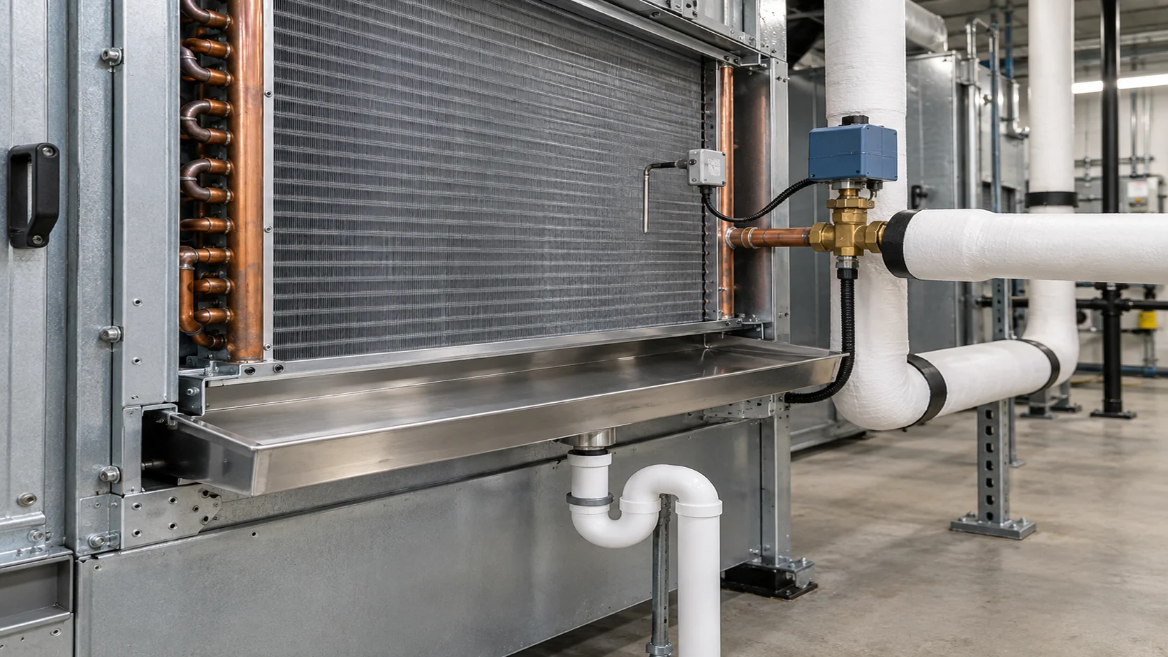
Cooling coils need a drain pan that catches the expected condensate at the design airflow. State pan material, slope, outlet location, trap depth, cleanout, and access. Put the trap and drain routing on the layout drawing. A pan that cannot be cleaned or a trap that is too shallow will turn a thermal problem into a water-damage problem.
Choose a layout that can be serviced
Draw-through arrangements place the fan downstream of the coil and can help pull air evenly through a coil, while blow-through arrangements place the fan upstream and may suit a compact or modular layout. Neither is universally better. Check fan heat, coil distribution, access, drain-pan position, and the pressure profile across filters and dampers.
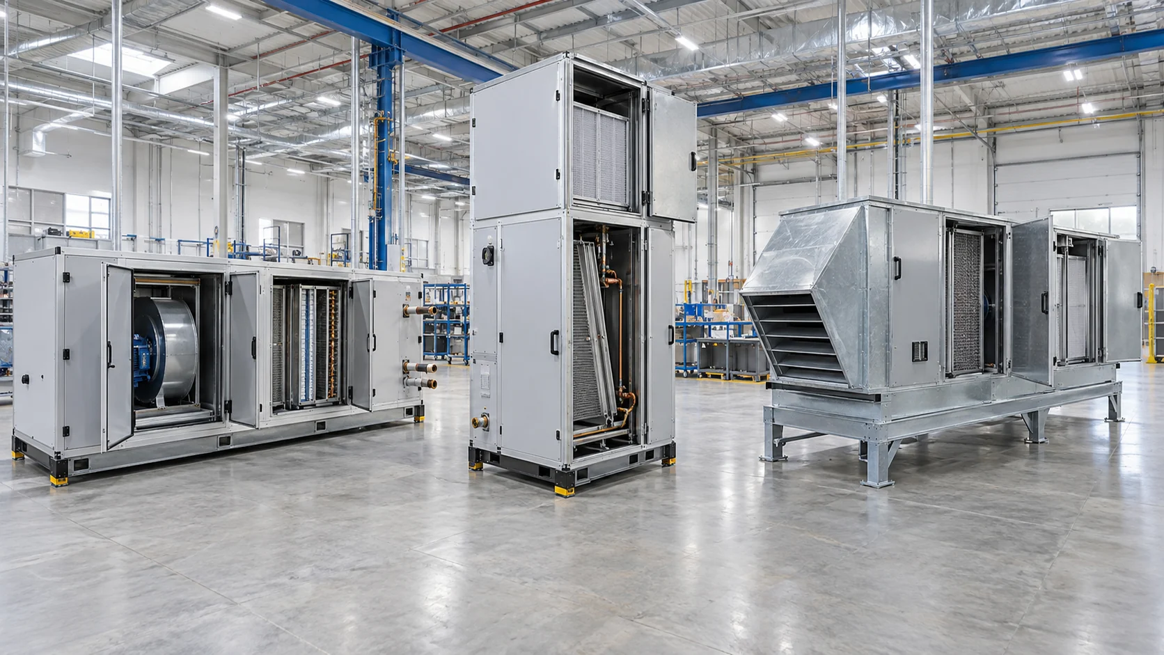
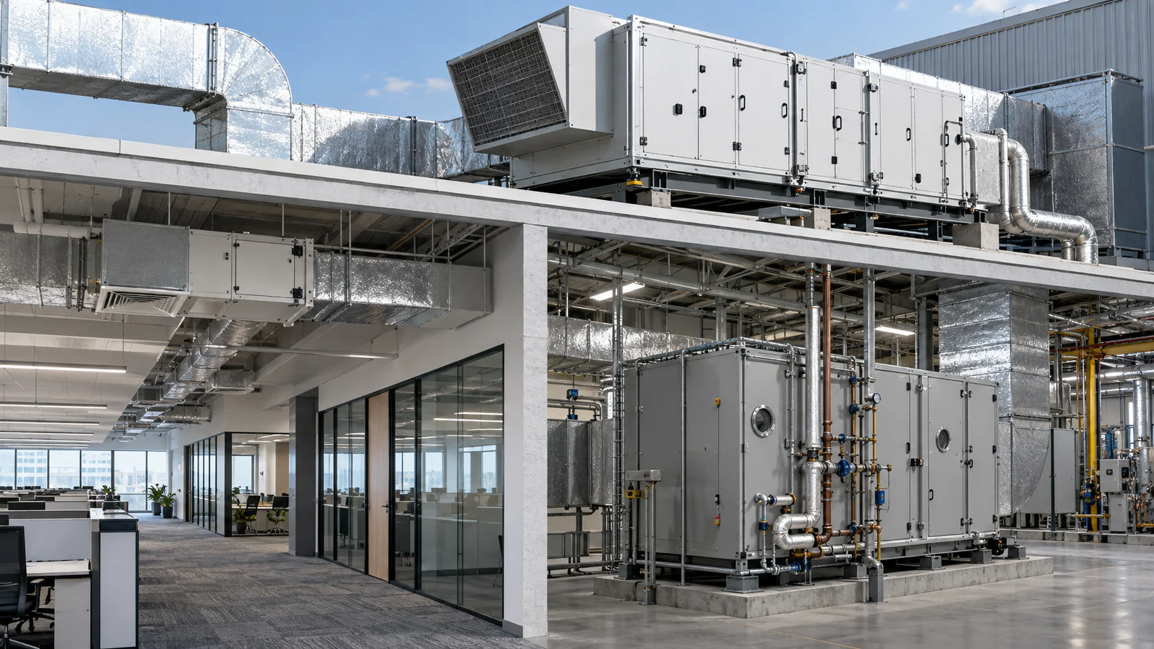
Horizontal, vertical, rooftop, and custom AHUs each create different lifting and maintenance constraints. A rooftop unit may need weather protection and a service platform. A vertical unit may fit a narrow plant room but require a taller coil removal path. A modular unit can be shipped in sections, but the field joints, controls wiring, and gasketed connections need a documented assembly sequence.
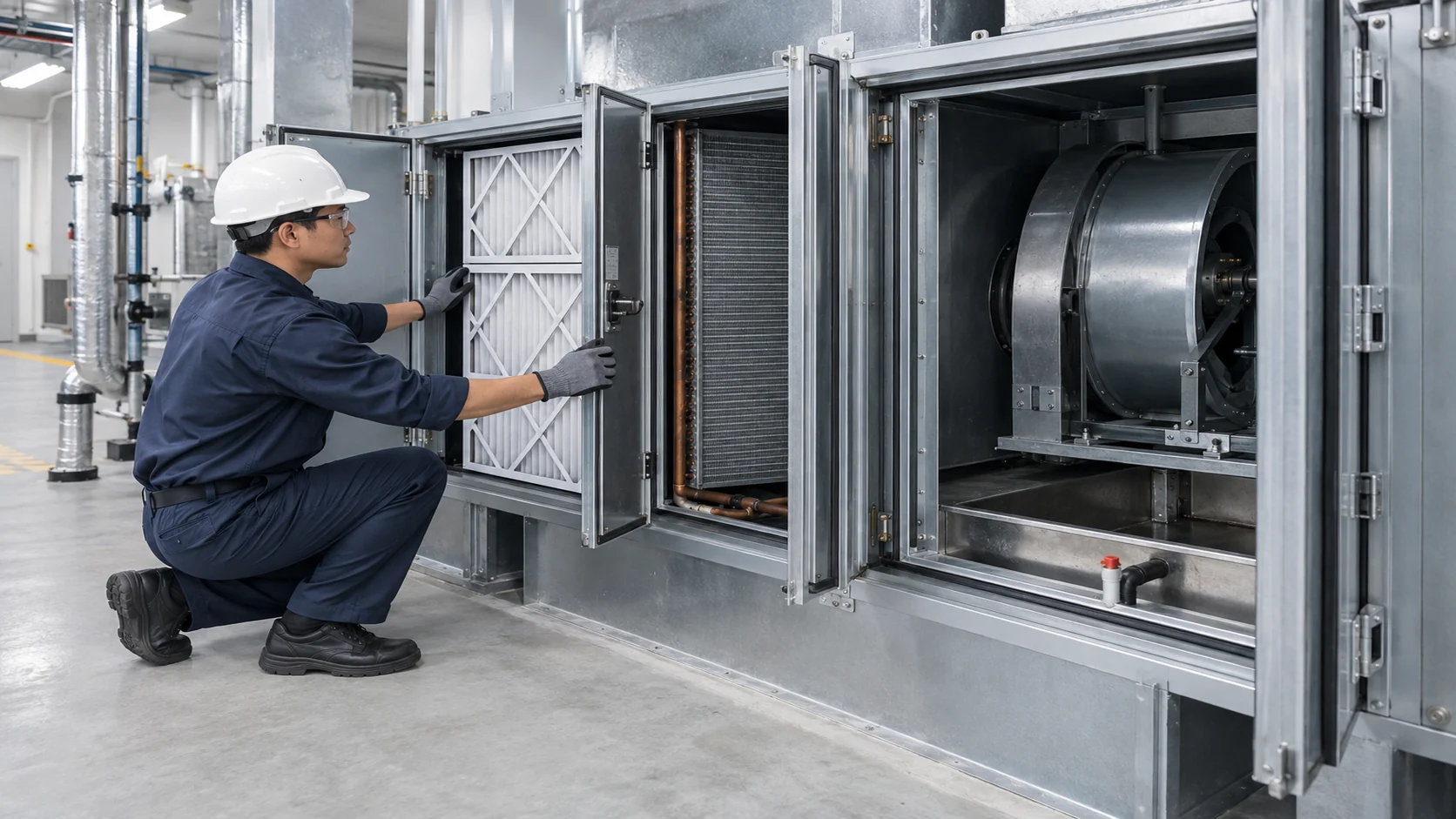
Make the removal path part of the purchase drawing. Show access doors, coil pull distance, filter slide-out length, motor service clearance, crane or trolley path, and the place where a drain pan can be removed. A cabinet that fits the room but cannot release a coil is not a maintainable selection.
Specify fans, motors, and controls as one pressure system
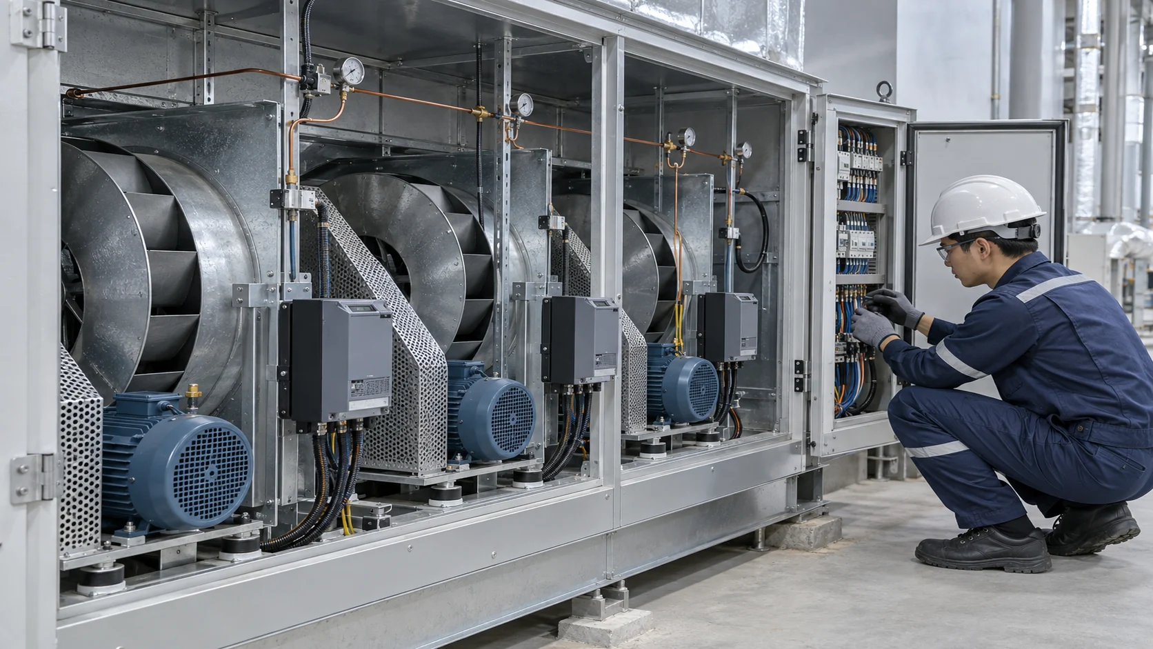
The fan schedule should identify airflow, total or static pressure basis, altitude, fan curve, speed, motor power, efficiency, sound, and the control range. State whether the quoted pressure includes clean or loaded filters, coils, dampers, silencers, and terminal devices. Ask for the fan operating point on the curve and the available margin at normal and minimum flow.
Variable-frequency drives and electronically commutated motors can reduce energy at part load, but they do not remove the need for a stable control sequence. Coordinate fan speed with chilled-water valves, heating valves, outdoor-air dampers, freeze protection, and building automation alarms. Include proof of airflow, high static pressure, dirty filter, freezestat, condensate overflow, smoke control, and access-door interlocks where the project requires them.
Sensor locations matter. Entering and leaving-air temperature probes should represent the mixed air and coil leaving air, not a stagnant corner. Differential-pressure taps across filters and coils need straight, serviceable tubing. For a replacement coil, retain the original control points only after checking that the new circuiting and pressure drop support the same sequence.
Manage outside air, mixing, and heat recovery
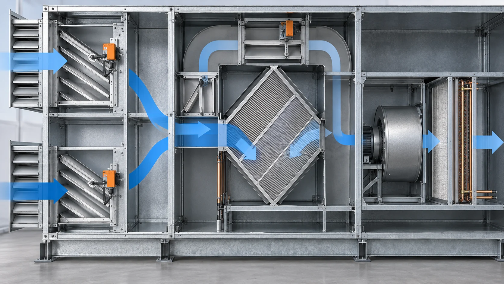
Outdoor-air fraction can change the AHU from a comfort unit into a dedicated outdoor-air system. Send the minimum ventilation rate, economizer range, return-air condition, relief-air path, and any exhaust contaminants. If the unit handles laboratory, kitchen, battery, or process exhaust, specify pressure relationships and leakage limits instead of using a comfort-HVAC assumption.
Mixing dampers need a control sequence that avoids short-circuiting outdoor air around the coil. In cold weather, the sequence may close an outdoor-air damper, maintain a minimum coil flow, or open a preheat valve. In mild weather, an economizer can increase outdoor air while reducing mechanical cooling. Heat recovery wheels, plates, or run-around loops need bypass and frost logic so that recovered energy does not create a frozen core or an unacceptable cross-leakage path.
Plan drain pans and freeze protection before release
Water coils in cold climates need more than a low setpoint. Confirm minimum flow, entering-air moisture, glycol concentration, valve fail position, low-temperature cutout, coil drainability, and the sequence used during shutdown. For a steam or hot-water preheat coil, confirm condensate drainage and the warm-up sequence. For a DX coil, coordinate defrost, suction pressure, refrigerant distribution, and oil return with the condensing unit.
Freeze protection must be testable. Identify sensor location, alarm delay, fan response, valve position, damper position, pump proof, and the manual reset policy. A freezestat installed downstream of a poorly mixed coil can respond too late. A sensor that trips but leaves the pump or outdoor-air damper uncontrolled can create a repeat event.
Match the AHU type to the application
For a comfort VAV system, the selection usually balances airflow turndown, filter pressure, sound, chilled-water coil performance, and controls integration. A dedicated outdoor-air unit gives ventilation and humidity more weight. An industrial AHU may need corrosion-resistant panels, washable filters, process exhaust compatibility, or a heat-recovery bypass. A data-center or high-tech manufacturing unit may require redundant fans, tight temperature control, and a documented alarm path.
Do not use a residential air-handler schedule for a multi-zone commercial unit. Residential pages can answer what an air handler is, but procurement decisions for a commercial AHU require airflow, pressure, service access, and control documentation. Define the application and operating modes in the first page of the RFQ so suppliers can make comparable assumptions.
| التطبيق | Selection priority | Extra information to send |
|---|---|---|
| Comfort VAV or office | Turndown, sound, filter life, chilled-water control, and BAS points | Zone schedule, minimum ventilation, terminal pressure, and occupied/unoccupied modes |
| Dedicated outdoor air | Humidity removal, mixed-air control, frost logic, and condensate handling | Outdoor-air percentage, dew point, exhaust path, heat recovery, and winter design condition |
| Industrial process room | Corrosion resistance, pressure relationship, cleanability, and alarm reliability | Process contaminants, room pressure, washdown chemicals, filtration target, and operating shifts |
| Data center or high-tech plant | Redundancy, tight leaving-air control, low fan energy, and service continuity | Rack or process heat profile, redundancy mode, allowable temperature band, and maintenance window |
Use the application matrix to keep the AHU schedule tied to the room or process. A coil can meet a laboratory load on paper and still fail the project if the casing, leakage, filtration, or service envelope does not match the environment.
Build a maintenance and access plan
Maintenance starts with the layout. Provide filter access from the correct side, coil cleaning clearance, fan and motor service space, drain-pan cleanout, lighting, and a safe isolation point. If the coil must be removed, show the path through doors, corridors, or roof hatches. Record the replacement part numbers for filters, belts, bearings, actuators, gaskets, and sensors.
Use operating data to set maintenance triggers. Track airflow, fan speed, filter differential pressure, coil entering and leaving temperatures, fluid pressure drop, valve position, condensate overflow alarms, and freeze trips. A rising filter pressure drop calls for filter service; a rising coil pressure drop with a widening leaving-air approach suggests fouling or a control problem. Keep the clean baseline with the handover documents.
RFQ fields that prevent hidden assumptions
Give every supplier the same schedule and ask each one to return assumptions in a visible section. Include:
- Application, indoor or outdoor location, operating modes, and target building or process zones.
- Supply, return, outdoor, and relief airflow for normal, minimum, peak, startup, and economizer cases.
- Entering and leaving air temperatures, humidity or dew point, altitude, and design-day assumptions.
- External static pressure and the pressure budget for filters, coils, dampers, sound attenuators, and terminals.
- Coil duty, fluid or refrigerant, concentration, flow, inlet and outlet temperatures, circuiting, and pressure-drop limits.
- Casing, insulation, panel, coating, drain-pan, filter, gasket, and connection materials.
- Fan type, motor, drive, sound limit, efficiency, speed range, redundancy, and controls interface.
- Damper leakage, minimum outdoor air, heat recovery, bypass, smoke control, freeze sequence, and alarm points.
- Footprint, height, weight, orientation, duct and pipe connections, access side, coil pull distance, and lifting route.
- Testing, inspection, documentation, spare parts, packaging, quantity, redundancy, and delivery requirements.

Ask for a selection sheet, fan curve, coil performance data, filter pressure-drop data, casing construction, wiring and controls points list, drain details, and a marked-up drawing. If a supplier cannot state the design pressure, test method, coil materials, or pressure-drop result, the quotation is not ready for a technical comparison.
When to use a custom AHU coil review
Use a custom coil review when the replacement must fit an existing casing, when airflow or pressure differs from a catalog case, when glycol or a corrosive fluid changes the material choice, or when a DX circuit needs new distributors and connections. A custom review is also useful when a standard coil cannot meet the face velocity, condensate, sound, or service-clearance requirements without a larger cabinet.
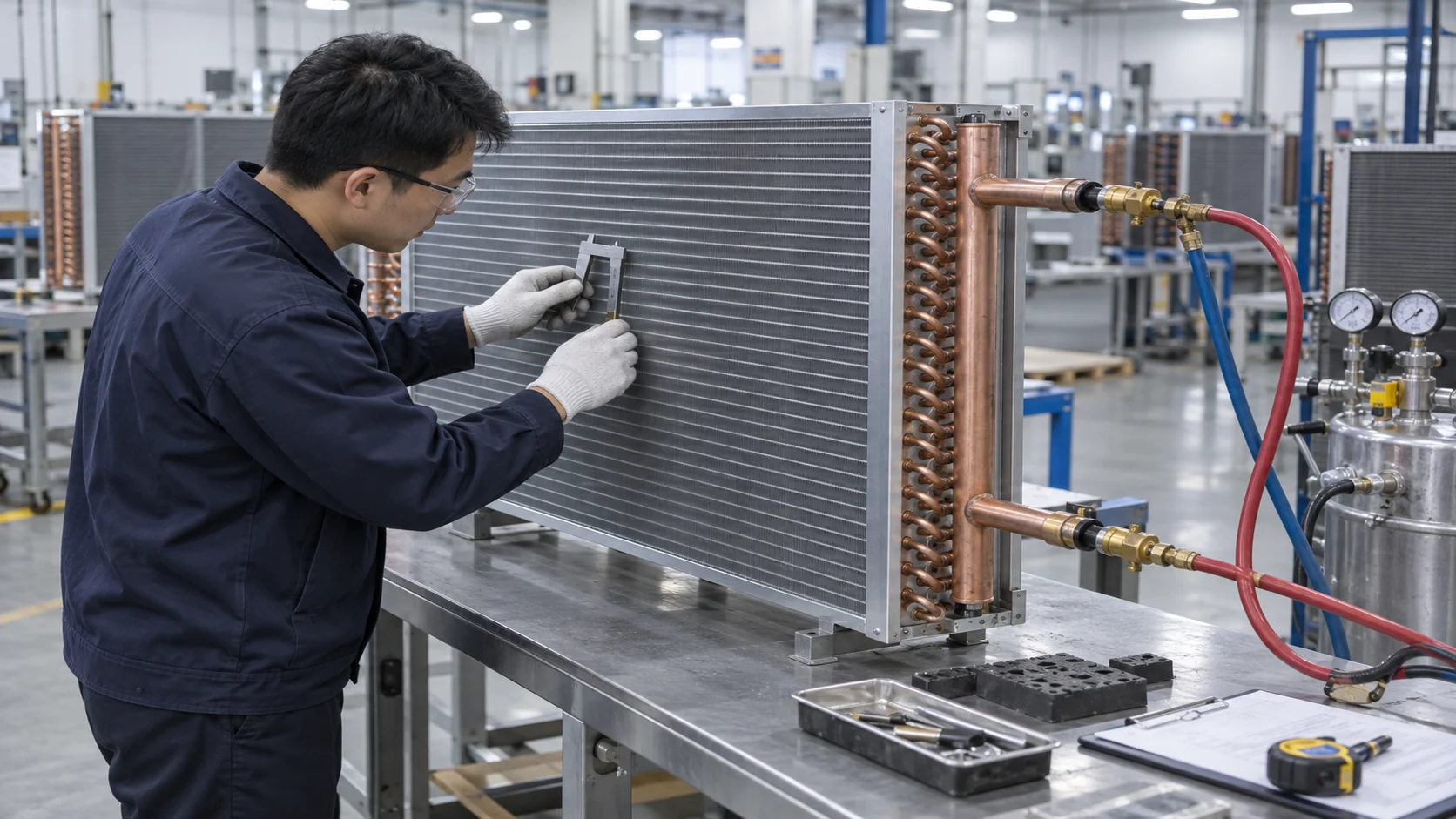
Domi Refrigeration’s visible scope includes custom coils, heat exchangers, thermal engineering, prototyping, testing, and quality documentation. For an AHU request, the correct starting point is a duty sheet and interface review, not a promise that a complete air-handler package is always supplied. Send the coil face dimensions, tube and fin material, fluid or refrigerant, airflow, entering and leaving conditions, connection locations, pressure-drop limits, drain details, photos, and the original drawing or nameplate.
استخدم خدمة تصنيع الملفات المخصصة for a prototype-to-production discussion, and review the مختبر اختبار المبادلات الحرارية و توثيق الجودة pages when defining inspection evidence.
الأسئلة الشائعة
What is an air handler?
An air handler is an HVAC cabinet that moves, filters, heats, cools, or dehumidifies air before distributing it through ductwork. It normally works with a chiller, boiler, heat pump, direct-expansion circuit, or heat-recovery device. The fan, filters, coils, dampers, drain pan, sensors, and controls must be selected as one airside and thermal system.
Is an air handler the same as an air handling unit?
In commercial HVAC, air handler and air handling unit, or AHU, usually describe the same equipment family. The naming does not define the capacity or construction. A small terminal air handler and a large outdoor AHU can have very different airflow, casing, coil, controls, and service requirements.
How do I size an air handler?
Start with airflow, external static pressure, entering and leaving air conditions, minimum outdoor air, filter pressure drop, coil duty, and operating range. Then select the fan, face area, coil rows and circuits, filters, dampers, casing, and controls together. Require a rated selection sheet for normal, minimum, and peak cases instead of sizing from nominal tons alone.
Which coil is best for a commercial air handler?
The right coil depends on the available heat-transfer source and the control sequence. Chilled-water, hot-water, steam, DX, and heat-recovery coils each need different fluid, pressure, temperature, material, and drainage inputs. Compare capacity, pressure drop, face velocity, materials, service access, and low-load behavior rather than choosing by tube diameter or row count alone.
How can I prevent an air-handler coil from freezing?
Confirm minimum flow, fluid concentration, entering-air condition, valve and damper fail positions, low-temperature sensors, drainability, and the shutdown sequence. Test the alarm and manual reset logic. For outdoor-air units, verify mixing and preheat performance at the coldest operating case instead of relying on a sensor installed after a poorly distributed coil.
What should be included in an air-handler RFQ?
Include airflow and static-pressure cases, air temperatures and humidity, outdoor-air fraction, coil fluid or refrigerant, capacity, pressure-drop limits, materials, filter class, casing, drain pan, fan and motor, controls points, access envelope, testing, documentation, quantity, and delivery requirements. Attach the existing drawing, nameplate, photos, and connection measurements for a replacement.
Send the air-handler data before you request pricing
An air handler is ready for comparable pricing when the airside duty, coil boundary, pressure budget, casing, controls, service path, and acceptance evidence are visible in one schedule. If the project needs a replacement or custom coil, send the dimensions and operating data first so the review can separate a coil-only solution from a complete AHU responsibility.
Send Your AHU Coil Schedule and Drawing for Review: اطلب عرض سعر مخصص.