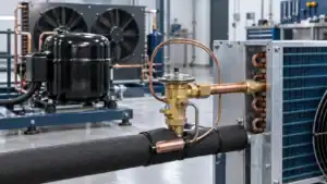
An electronic expansion valve (EEV) meters refrigerant into an evaporator under electronic control. To select one, match its capacity at the actual refrigerant and operating conditions, then verify the valve actuator, controller, sensors, flow direction, and application against the same manufacturer’s documentation. Nominal system tonnage alone is not enough to choose a model.
This guide is for OEM, commercial refrigeration, and heat-pump buyers reviewing an EEV for a new system or replacement. Domi Refrigeration does not list EEVs for sale. Valve model, driver, wiring, and service questions belong with the valve or controller manufacturer; Domi’s relevant scope is custom heat-exchanger coils and engineering review when the coil is part of the project.
What an electronic expansion valve does
An expansion valve controls the refrigerant mass flow entering an evaporator. The pressure drop across the valve helps establish the low-side condition where the refrigerant can boil and absorb heat. The EEV changes its opening in response to an electronic controller. Depending on the model, the actuator can position a needle continuously or use another electrical modulation method.
In many systems, the controller uses evaporator outlet pressure and temperature to calculate superheat. It then commands the valve to add or restrict refrigerant while protecting the compressor from liquid return. This is a control loop, not a stand-alone valve function: the controller, sensor type, refrigerant setting, firmware, actuator, and valve must be compatible. ASHRAE’s current refrigerant-control chapter describes electronic valves as an application pairing of valve, controller, and sensing inputs, with several actuator families rather than one universal EEV design (ASHRAE Handbook, Chapter 11).
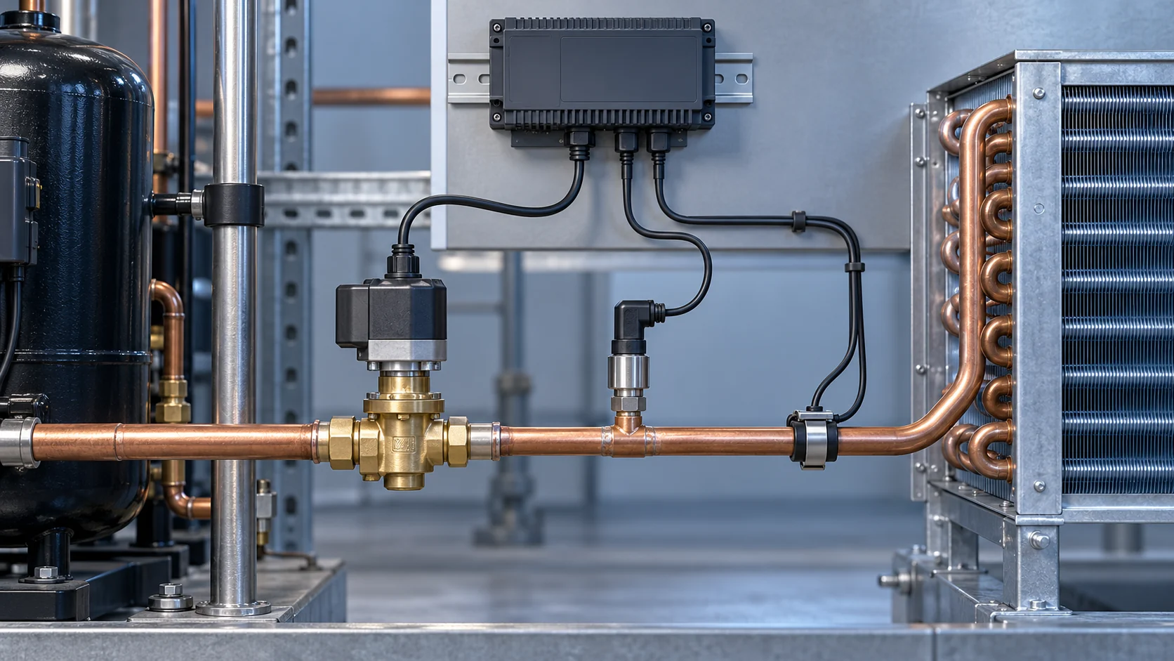
Concept illustration: electronic expansion valve, sensors, controller connection, and evaporator flow path.
How an EEV control loop works
The exact control sequence is set by the system designer and controller maker, but a common superheat-control sequence is:
- A pressure transducer measures pressure at the specified evaporator location.
- A temperature sensor reads refrigerant-line temperature at the specified outlet location.
- The controller uses the selected refrigerant pressure-temperature relationship to calculate saturation temperature and superheat.
- The control algorithm compares the reading with its target and sends a compatible drive signal to the EEV actuator.
- The valve changes its opening; the sensor readings update and the loop repeats.
Superheat is the measured vapor temperature above the saturation temperature associated with the same pressure. Sensor placement, refrigerant selection, filtering, control limits, and startup behavior must follow the controller and system documentation. A poorly located sensor or wrong refrigerant setting can make a correctly operating valve appear unstable. CAREL’s driver manual describes pressure-derived saturation temperature combined with outlet gas temperature for its superheat calculation; that is an implementation example, not a universal controller rule (CAREL EEV Superheat Driver manual).
EEV actuator types and what they change
The phrase electronic expansion valve covers different actuator methods. Confirm the exact family in the product datasheet before choosing a controller or writing a wiring specification.
- Stepper motor: Moves the valve in discrete commanded steps. The driver must match the motor winding and required sequence, step count, and operating limits. Many modulating refrigeration EEV product lines use stepper actuators, but their electrical details are model-specific.
- Pulse-width-modulated valve: Uses repeated on/off pulses to regulate average flow. Confirm the required drive frequency and control interface for the selected valve.
- Heat-motor actuator: Uses an electrically heated element to move the valve mechanism. Response and electrical setup depend on the design.
- Magnetic modulation: Uses a magnetic actuator to vary opening or flow. The controller and valve must be designed to work together.
These actuator types are not interchangeable simply because each is called an EEV. ASHRAE’s control-device guidance discusses step-motor, PWM, heat-motor, and magnetic modulation designs. The component pairings and rated control conditions remain manufacturer-specific.
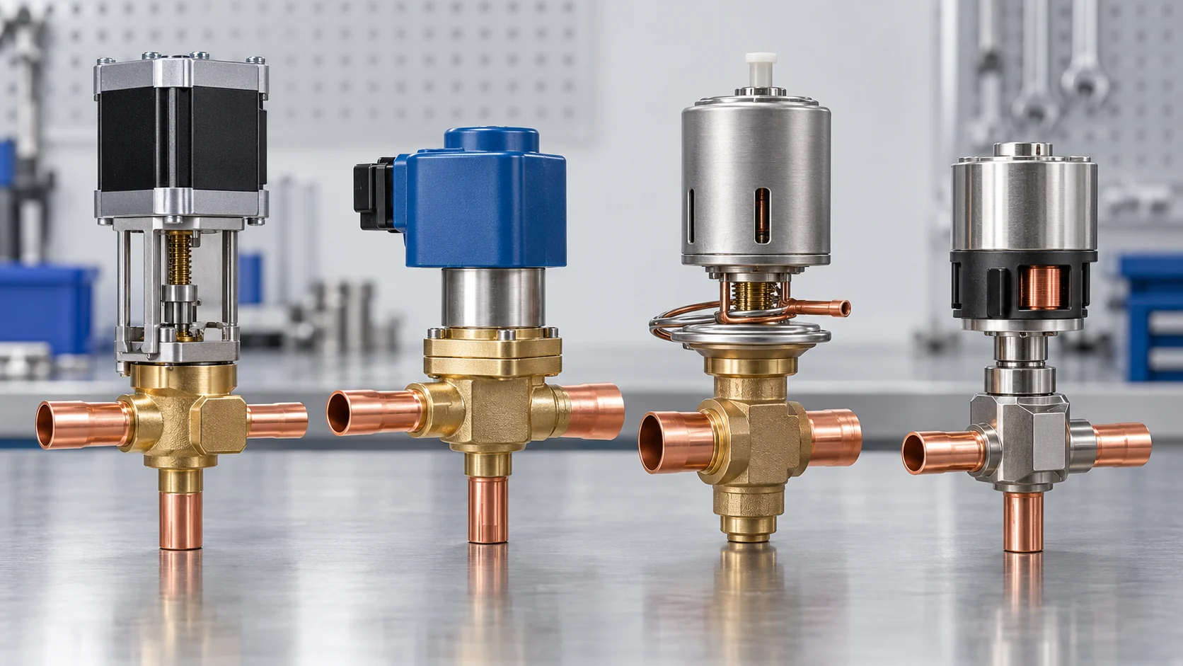
Concept illustration: representative electronic valve actuator mechanisms. The artwork is not a construction drawing.
EEV vs TXV: the practical difference
Both an electronic expansion valve and a thermostatic expansion valve meter refrigerant to the evaporator. They differ in how the opening is controlled and what must be integrated around the valve.
- EEV: Uses an electrical actuator controlled by an electronic driver. The system typically needs compatible sensing and control logic. This gives the equipment designer a configurable control architecture, but adds wiring, sensor, parameter, and commissioning requirements.
- TXV: Uses a thermostatic mechanism, commonly including a sensing bulb and pressure element, to regulate superheat without a separate electronic valve driver. Its selection and installation still depend on refrigerant, capacity, pressure conditions, equalization, orientation, and the manufacturer’s application data.
- Selection decision: Compare the system’s control requirements, turndown and operating range, existing controller platform, service capability, validated model capacity, and total integration effort. There is no universal rule that an EEV is always more efficient or that a TXV is always simpler for every application.
For a deeper TXV-specific selection path, see Domi’s guide de la vanne d'expansion thermostatique. This article focuses on EEV selection and integration.
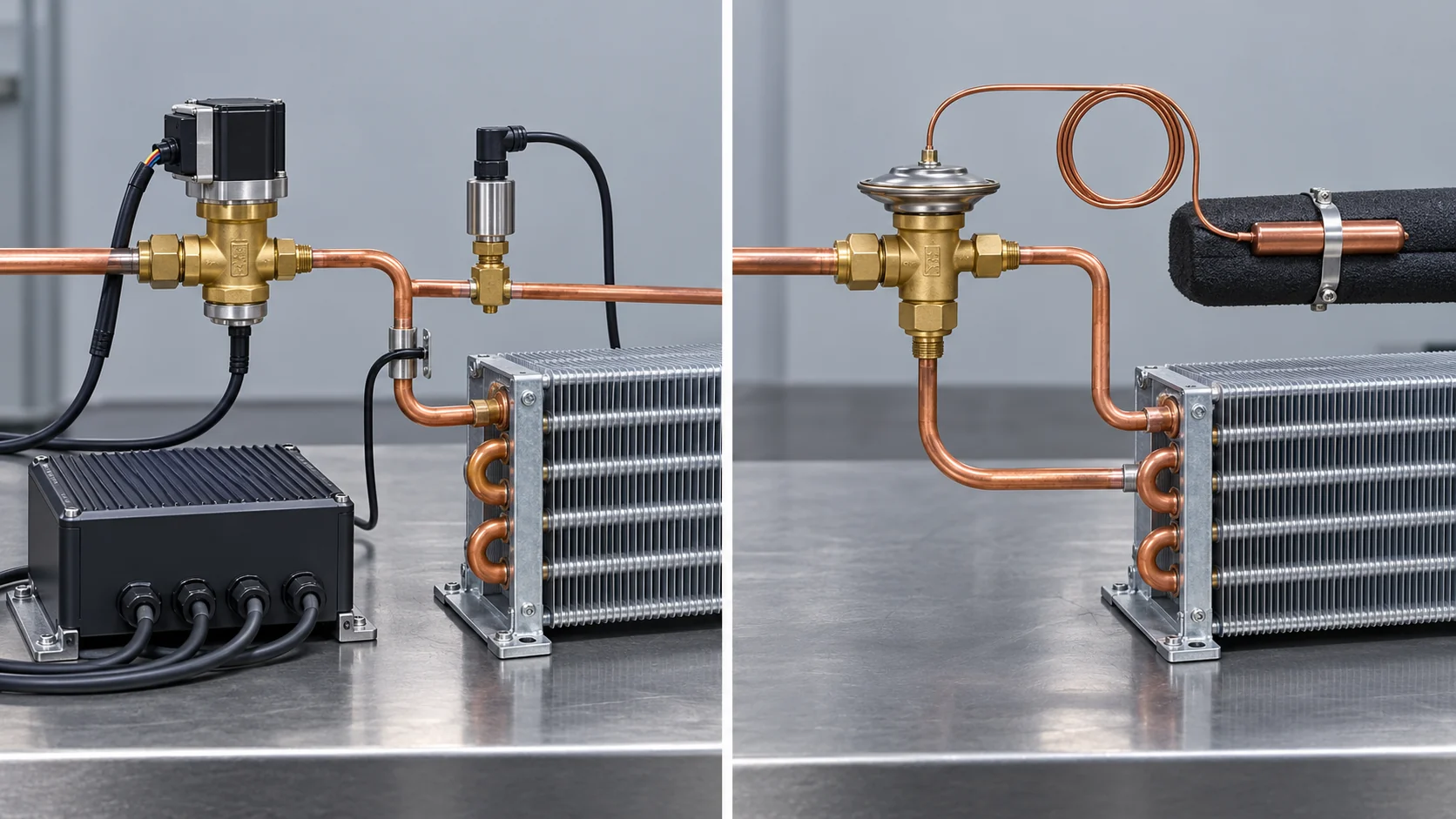
Concept illustration: electronic sensing and drive versus a self-acting thermostatic valve arrangement.
How to size an electronic expansion valve
Use the valve manufacturer’s rating software or selection tables with the design case. A capacity value only applies to its stated refrigerant and rating conditions. For example, a Danfoss ETS datasheet shows capacity selection changing with refrigerant, evaporating condition, subcooling, and pressure drop. Its values apply to those named models and conditions, not to all EEVs (Danfoss ETS datasheet, March 2026).
Collect these inputs before asking for a model recommendation:
- Refrigerant and blend: State the exact refrigerant designation and any relevant composition. Do not substitute a refrigerant family label for a specific blend.
- Required duty: Give design cooling or heating duty, units, load profile, and whether the value is at steady state, pull-down, or another condition.
- Operating temperatures: Specify evaporating temperature, condensing or gas-cooler condition, and liquid temperature or subcooling at the valve inlet.
- Pressure conditions: Provide expected pressure drop across the valve and system pressure envelope. The same valve can have a different capacity at another pressure differential.
- Flow range: Include minimum and maximum load, startup, low-ambient, defrost recovery, and other operating points relevant to the equipment.
- Circuit interface: Record distributor type, number of evaporator circuits, inlet connection, allowable pressure drop, and any known liquid-line or flash-gas constraints.
- Valve limits: Check minimum stable capacity, maximum working pressure, temperature range, compatible refrigerants, leakage or shutoff requirements, and directionality where relevant.
Ask the manufacturer to return the selected model, rated capacity at each design point, usable operating envelope, pressure-drop assumption, and recommended selection software or revision. Do not size by port diameter, connection size, nominal tonnage, or a single catalog capacity number alone.
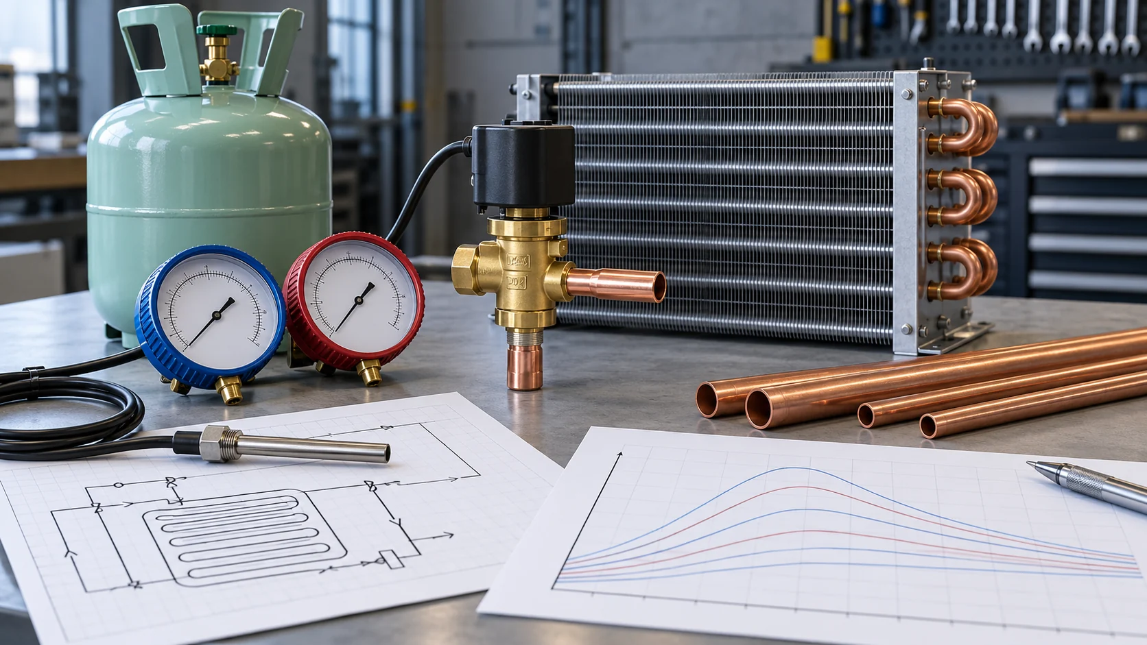
Concept illustration: the operating conditions that affect a model-specific EEV capacity check.
EEV controller, driver, and sensor compatibility
Treat the valve and driver as a matched control set unless the manufacturers explicitly publish a supported combination. The controller’s label or generic output type is not enough to establish compatibility.
Verify each item against the EEV and controller manuals:
- actuator family and electrical drive method;
- number and type of motor phases or required modulation method;
- compatible controller model, firmware, valve profile, and setup procedure;
- supply and output ratings for the specific actuator;
- pressure transducer range, signal type, and refrigerant configuration;
- temperature sensor type, input range, and placement instructions;
- cable, connector, grounding, routing, and electrical-noise requirements;
- reset, initialization, homing, fail-safe, and alarm behavior after power interruption.
Never assume that a voltage, coil resistance, connector pinout, or step count applies to all EEVs. Parker’s SERI installation material, for example, gives instructions for that product family and compatible controls; it should not be copied into another valve’s commissioning spec (Parker Sporlan SERI installation and service guide).
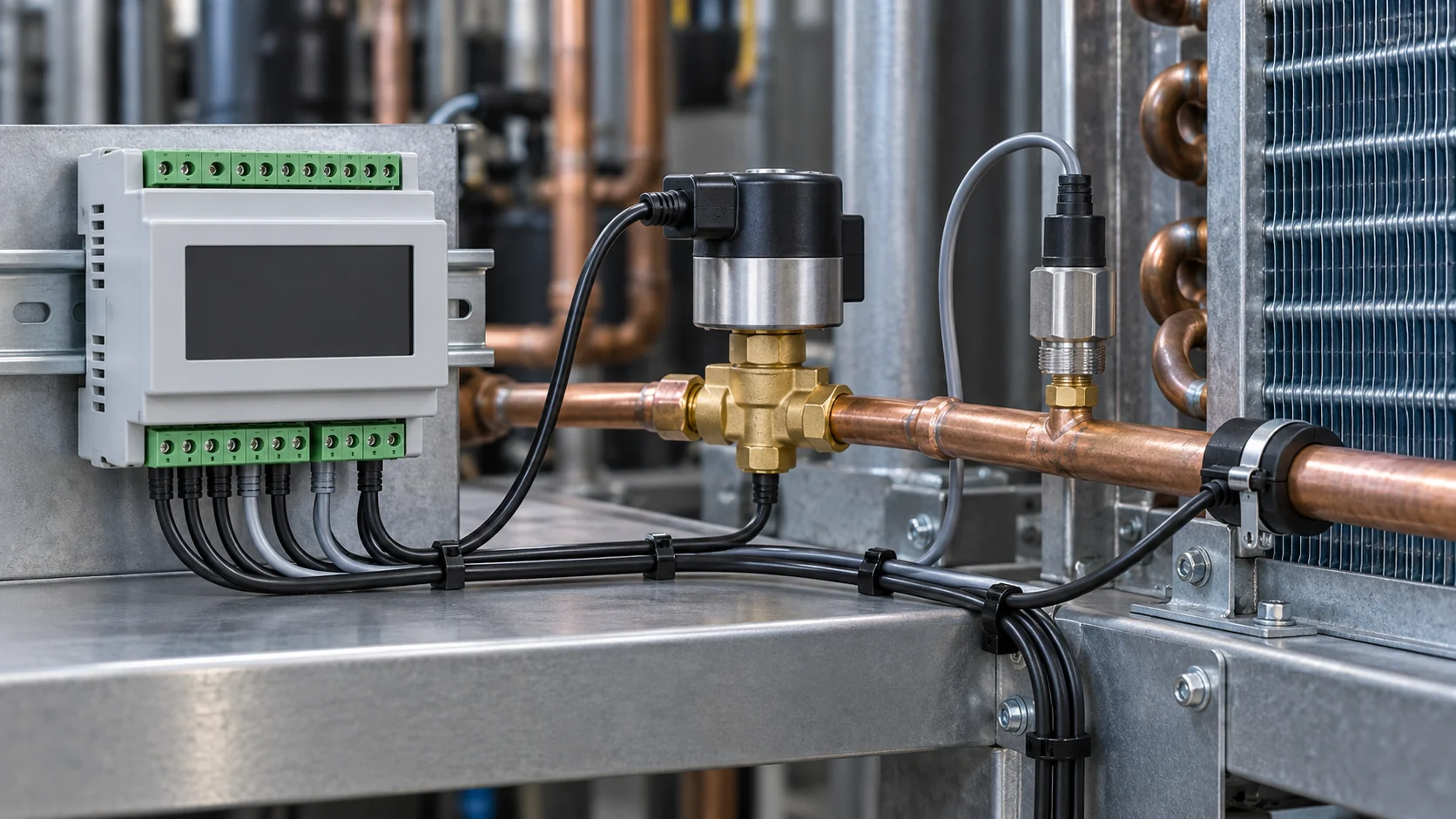
Concept illustration: control hardware and sensor connections that must be matched to the selected EEV.
Check the evaporator distributor and coil interface
The EEV’s job is to meter flow; the distributor and evaporator circuiting must distribute that refrigerant as the system design requires. An EEV that passes a capacity selection check can still be paired with an unsuitable distributor, circuit count, inlet geometry, or evaporator duty.
Provide the coil or system designer with the selected valve model, refrigerant, design duty, inlet state, pressure drop available, distributor details, circuit count, evaporating condition, airflow or fluid-side conditions, and control strategy. The designer can review whether the coil circuiting and distributor are appropriate for the expected mass flow and load range. That is an interface review, not a substitute for selecting the valve with its manufacturer.
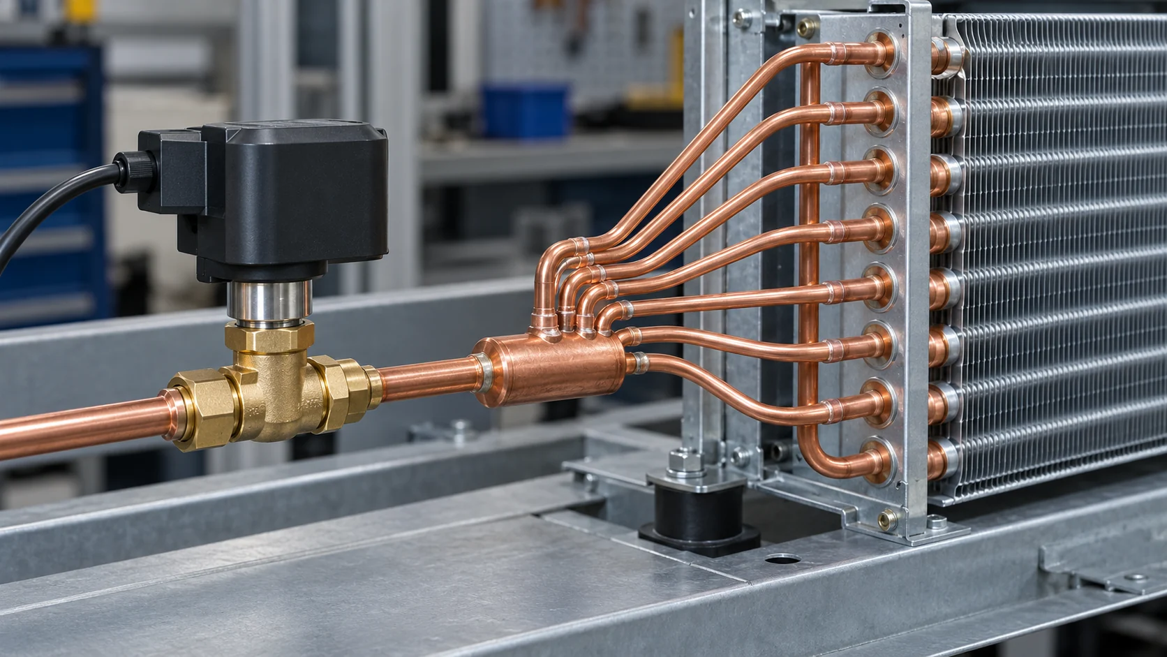
Concept illustration: the valve-to-distributor-to-multiple-circuit evaporator interface.
For a reversible heat pump or another bidirectional application, confirm that the selected valve and system arrangement are approved for the intended direction and operating states. Do not assume that every EEV can meter in both directions. Confirm check-valve or bypass architecture, control sequence, and ratings in the system and valve documentation. Refrigerant-specific applications, including transcritical CO2, require the correct design method and model data; do not transfer a sizing rule of thumb from another refrigerant or pressure range.
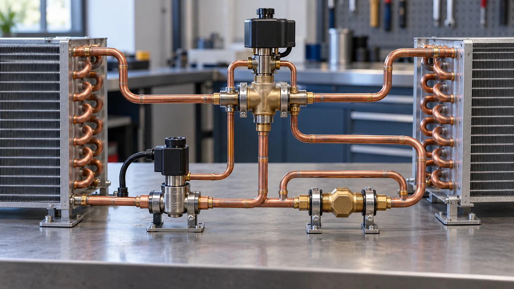
Concept illustration: flow paths in a heat-pump circuit. Actual bidirectional valve capability is model-specific.
Contrôles d'installation et de mise en service
Follow the selected product’s installation manual and qualified service procedures. An article cannot replace the manufacturer’s instructions, code requirements, refrigerant-handling rules, or site safety plan. Before energizing the system, the project record should confirm:
- valve model, refrigerant, flow arrow or permitted direction, and approved mounting orientation;
- clean piping, correct filter-drier or strainer arrangement, and protection from debris or moisture;
- brazing heat protection, evacuation, leak checks, and pressure testing as specified by the manufacturer;
- controller model, wiring, sensor type and location, parameter profile, and configured refrigerant;
- initialization or homing procedure and successful actuator response;
- stable readings at startup and at documented low-load and design-load conditions;
- alarms, fail-safe response, power-loss behavior, and recovery after restart.
Some steps differ by valve family. For instance, Parker’s SERI manual has product-specific installation cautions and initialization instructions. Use the manual for the exact model rather than copying a generic checklist as a work instruction. ASHRAE Standard 17 describes test methods for expansion-valve capacity; it is a test standard scope, not a field commissioning recipe (ASHRAE Standards, titles and scopes).
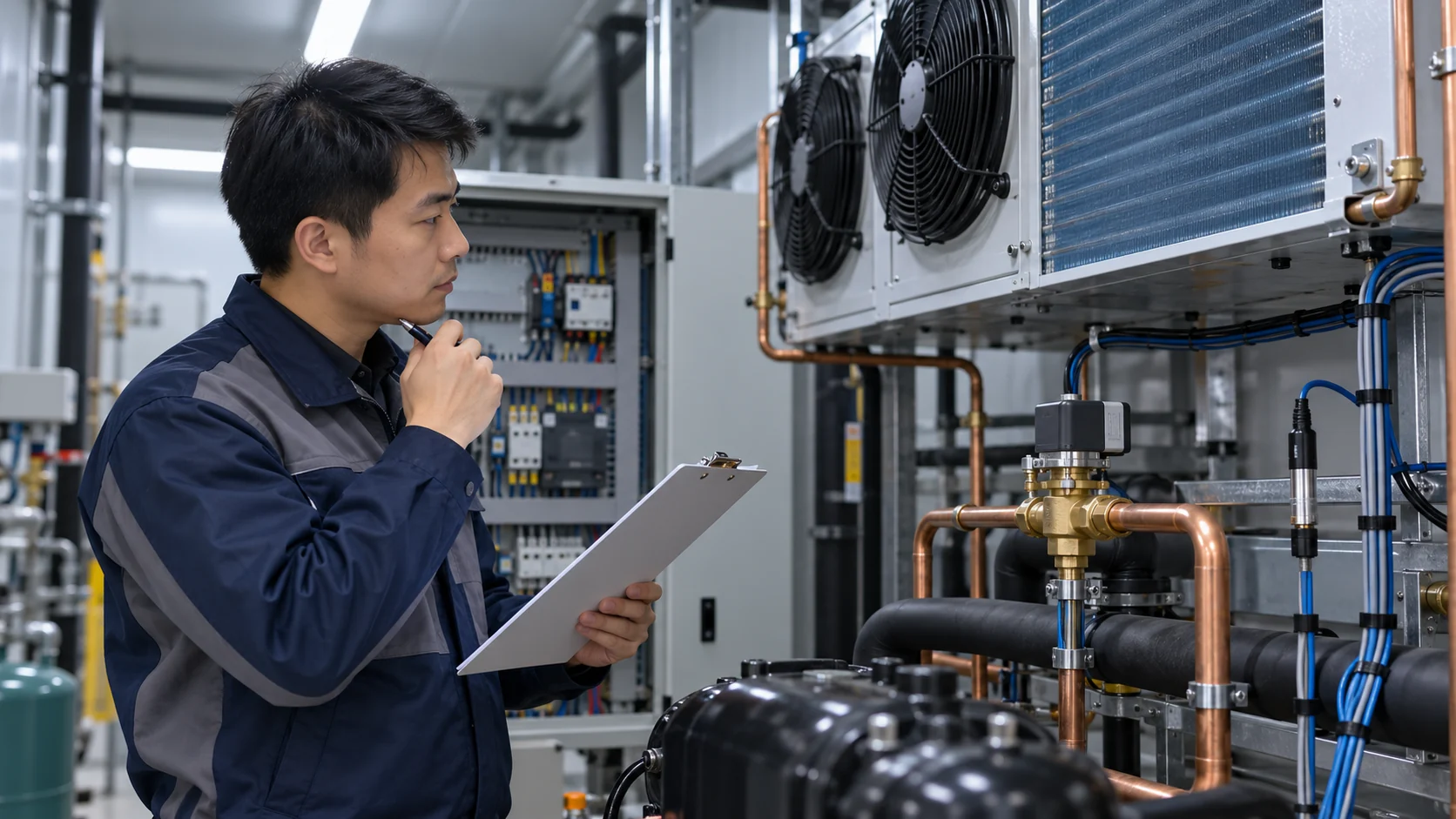
Concept illustration: a commissioning record review. It is not a Domi test or validation record.
EEV troubleshooting: what symptoms can and cannot tell you
A valve fault is only one possible cause of unstable superheat, poor cooling, icing, unusual pressure, or compressor protection trips. Start with safe system measurements and the controller’s alarms and trend data. A qualified refrigeration technician should isolate electrical, pressure, and refrigerant causes using the system maker’s service procedure.
A useful fault-isolation order is:
- Confirm the operating state. Record load, ambient condition, setpoint, defrost or startup state, and the exact alarm before changing settings.
- Validate sensor data. Check sensor identity, wiring, location, connector, calibration or plausibility, and the refrigerant selected in the controller.
- Review the controller and drive. Confirm the valve profile, firmware, output signal, initialization state, alarm history, and commanded position according to the manual.
- Check the refrigerant circuit. Review charge, liquid supply, filter or strainer condition, moisture or contamination, pressure drop, and other restrictions using approved procedures.
- Compare command and response. Determine whether the actuator receives the intended signal and whether measured system response follows it. Electrical tests and safe isolation must use the exact product instructions.
- Decide whether replacement is supported by evidence. Document the model and serial, controller and software, sensor readings, measured conditions, alarm record, and checks already completed before contacting the manufacturer.
Symptoms alone do not prove that an EEV has failed. A mismatched controller, sensor error, insufficient pressure differential, liquid-line restriction, refrigerant charge problem, wiring fault, or incorrect setup can produce similar behavior.
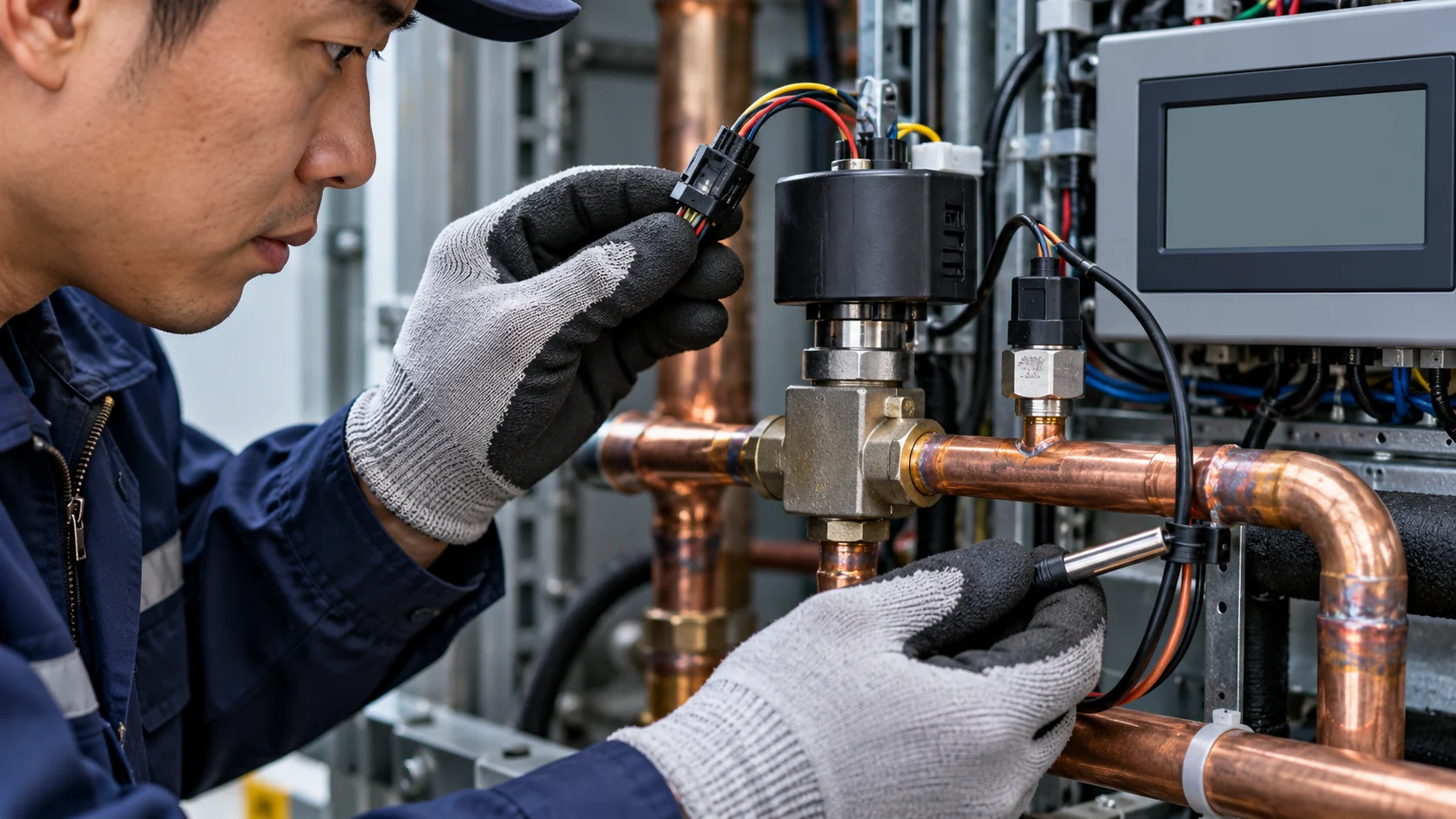
Concept illustration: a technician compares sensor, controller, and refrigerant-circuit evidence before replacing a valve.
EEV replacement cost and model replacement
There is no reliable universal replacement price. The part cost depends on model, refrigerant approval, capacity, actuator, connection, supplier, and availability. Labor and total job cost depend on system access, refrigerant recovery, isolation or shutdown, electrical/control changes, commissioning, and any required repair to the circuit or controller.
Before ordering a replacement, record the full valve model and revision, controller and firmware, refrigerant, design and measured operating conditions, actuator wiring, connection details, flow direction, and the reason for failure. Ask the OEM or authorized service supplier to confirm a direct replacement or a documented approved alternative. Replacing a valve with a similar-looking body is not enough to establish capacity or control compatibility.
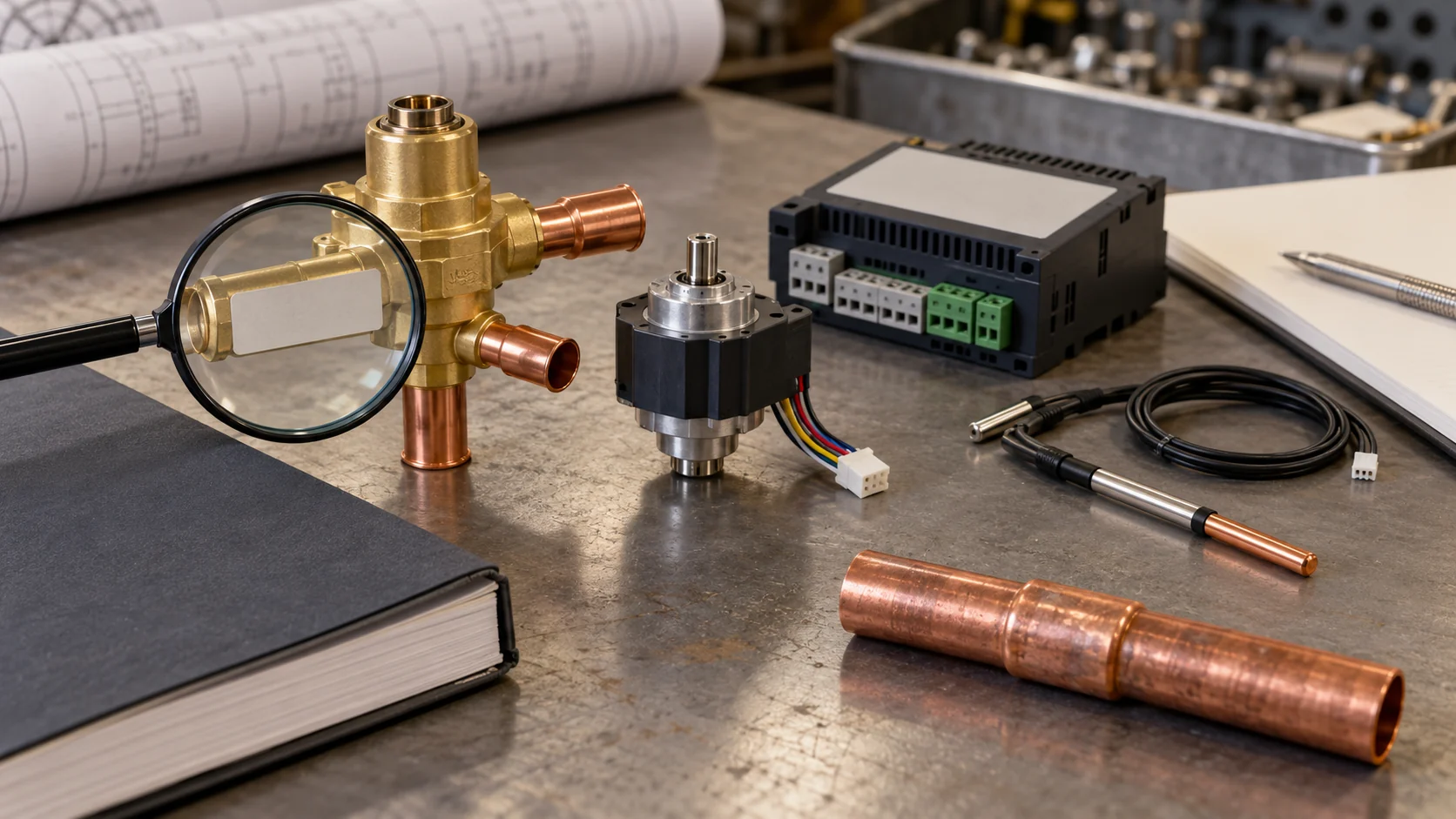
Concept illustration: checking a valve model against its documentation. No product rating is represented.
Electronic expansion valve RFQ checklist
Send one package to the valve or controller manufacturer rather than requesting a price from a valve photo alone. Include:
- project type and intended application;
- refrigerant and system type, including heat-pump or reversible operation;
- required duty and operating points with units;
- evaporating, condensing or gas-cooler, liquid, and ambient conditions;
- pressure differential available across the valve;
- minimum and maximum load or mass-flow requirement;
- evaporator or gas-cooler distributor, circuit count, connection sizes, and piping sketch;
- valve actuator type, existing controller and firmware, sensor details, power/control supply, and wiring diagram if replacing a valve;
- required pressure envelope, ambient range, leakage/shutoff requirement, mounting constraints, and approvals;
- expected startup, low-load, defrost, pull-down, and fault-recovery states;
- request for the selected part number, rating at each operating point, compatible driver/sensor set, software or configuration file, lead time, and commissioning instructions.
Ask the supplier to identify assumptions and exclusions in writing. If the duty data are incomplete, request a list of missing information rather than allowing assumptions to be mistaken for a confirmed selection.
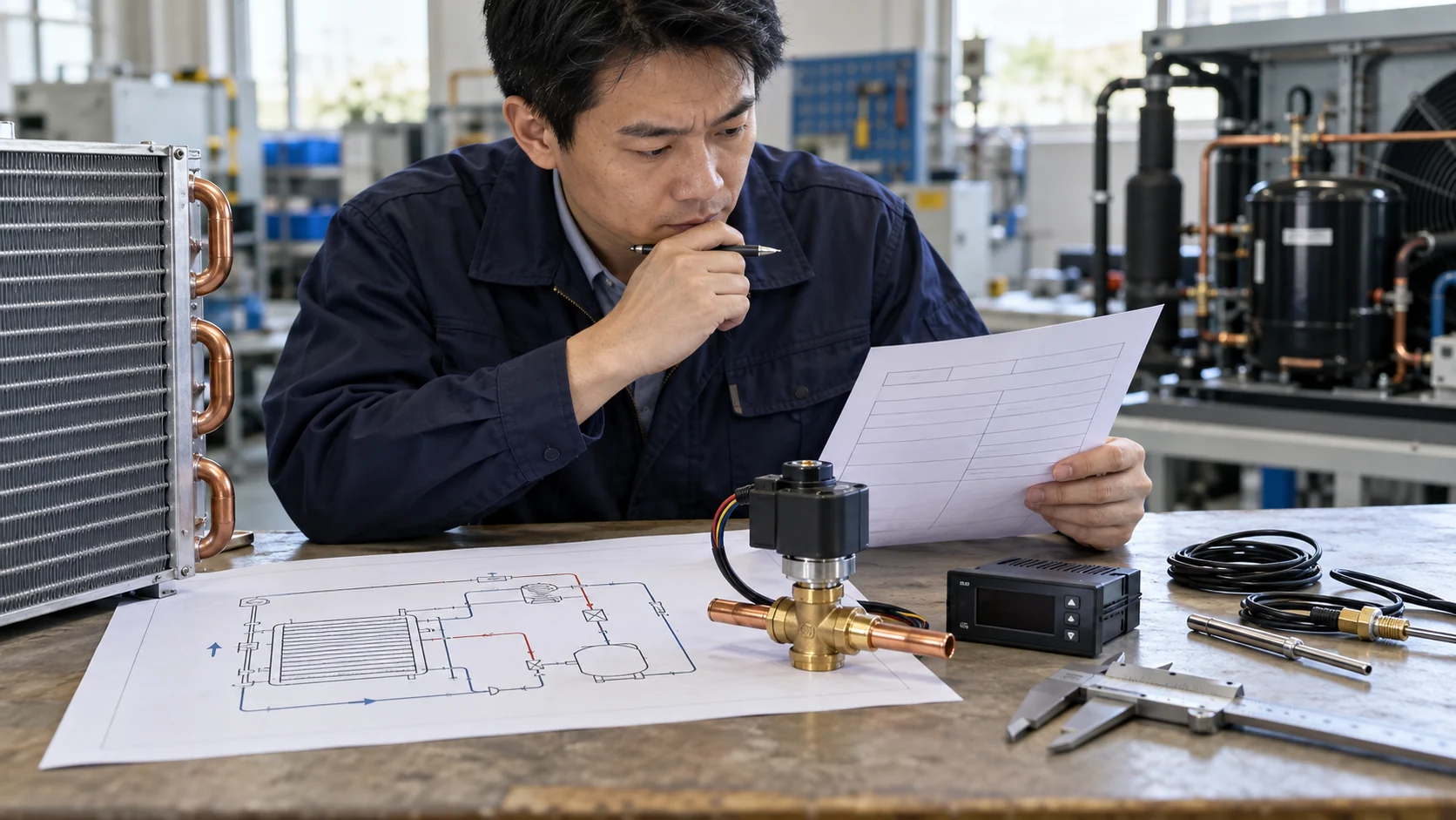
Concept illustration: a buyer’s valve-selection package with a system sketch, operating data, and controller records.
When the project also needs a custom refrigeration coil
If the EEV is part of an OEM coil package, send the valve selection data with the coil drawing or duty point so the coil circuiting and distributor interface can be reviewed together. Domi’s published scope covers custom condenser, evaporator, and industrial coils based on drawings, samples, or operating requirements, plus engineering support such as thermal calculations, CAD review, and circuiting development. That is a coil and interface discussion; the valve itself and control pairing remain with the valve/controller manufacturer. See Domi’s custom coil fabrication et capacités d’ingénierie.
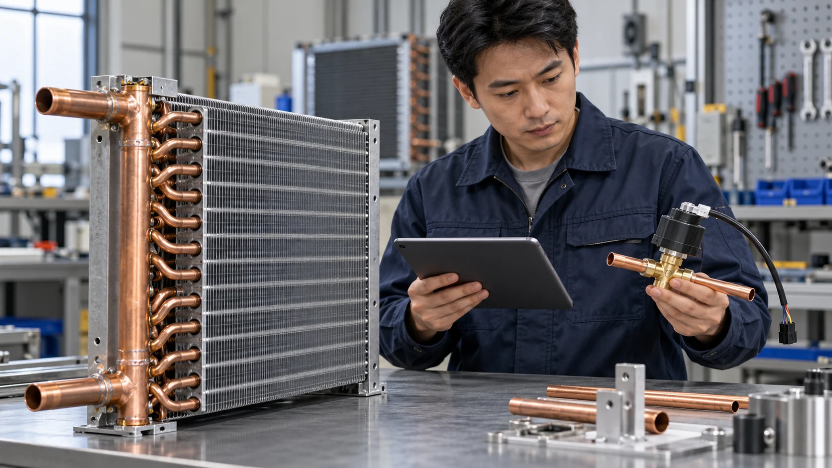
Concept illustration: a coil drawing and EEV interface records at an engineering review. It does not depict a Domi project.
Have a custom coil in the same project? Send the coil drawing or duty conditions, refrigerant, selected EEV model, distributor and circuit details, and target operating points for a coil-interface review.
Questions fréquemment posées
What does an electronic expansion valve do?
An electronic expansion valve meters refrigerant into an evaporator. A compatible electronic controller changes the valve opening based on sensor inputs and the system control strategy.
How does an electronic expansion valve work?
A controller reads pressure and temperature inputs, applies its configured refrigerant and control logic, and commands a compatible actuator. In a common superheat loop, it compares measured outlet superheat with a target and adjusts flow. Sensor placement and control sequence depend on the system and controller maker.
What is the difference between an EEV and a TXV?
An EEV is driven by an electronic controller and requires compatible electrical actuation and sensing. A TXV uses a thermostatic mechanism, commonly including a sensing bulb, to regulate superheat. Compare the complete application, control system, operating range, service support, and model ratings before choosing.
How do you size an electronic expansion valve?
Use the manufacturer’s selection software or tables for the exact refrigerant, duty, evaporating and condensing conditions, inlet liquid condition, and pressure drop. Check minimum and maximum load, application limits, actuator/controller match, and distributor interface. Nominal tonnage by itself is insufficient.
How do I know if my EEV is bad?
Unstable superheat, poor capacity, alarms, or unusual pressure are clues, not proof. Check sensor readings and configuration, wiring, controller drive and initialization, refrigerant supply, restrictions, pressure differential, and system state before concluding the valve has failed. Use qualified service and the exact model’s instructions.
How much does it cost to replace an electronic expansion valve?
There is no universal price. Cost depends on the exact valve and controller combination, refrigerant and connection requirements, supplier, access, recovery and service work, and commissioning. Request a model-specific quote after the application and existing control setup are documented.
Can one EEV controller operate any electronic expansion valve?
No. Match the controller output, valve actuator, wiring, valve profile, sensors, refrigerant configuration, and firmware using the manufacturers’ compatibility information. Similar connectors or nominal voltages do not prove a supported pairing.
Can an EEV work in both directions in a heat pump?
Only when the selected valve and system arrangement are approved for the required flow directions and operating states. Verify directionality, check-valve or bypass design, control logic, and pressure ratings for the exact model and system.