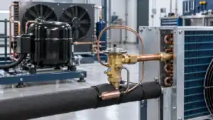
Short answer: a heat pump system is a reversible vapor-compression system that moves heat between a conditioned space and an outdoor air, water, or ground source. Its core hardware normally includes a compressor, two heat-transfer coils, expansion devices, a reversing valve for reversible operation, fans or pumps, controls, and the mechanical interfaces that make the package manufacturable. For an OEM quotation, the system name is not enough: the supplier also needs the load, operating temperatures, airflow or fluid flow, refrigerant, pressure-drop limits, envelope, drainage, controls, and validation target.
The important distinction for a buyer is that a coil’s job changes with operating mode. In heating mode, the outdoor coil commonly acts as the evaporator and the indoor coil releases heat as the condenser. In cooling mode, the refrigerant direction changes and the roles reverse. That is why a heat-pump coil should be reviewed as part of a matched system rather than as an isolated fin pack. This guide maps the system boundary to the information needed for a custom heat-pump coil or heat exchanger RFQ.
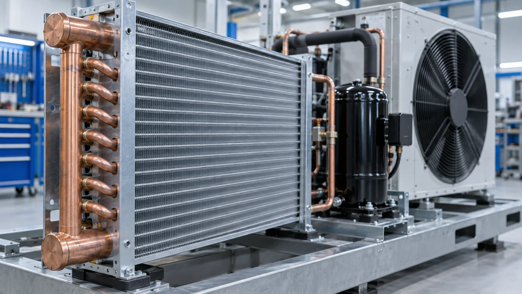
What is a heat pump system?
A heat pump uses electrical or thermal energy to move heat instead of creating all of the useful heating effect directly. The U.S. Department of Energy describes air-source heat pumps as systems that move heat between a building and outdoor air, while ground-source and other configurations use a different heat source or sink. The final selection depends on the building or process load, climate, source temperature, distribution method, controls, service plan, and applicable requirements. See the Department of Energy heat pump systems overview for the general system categories.
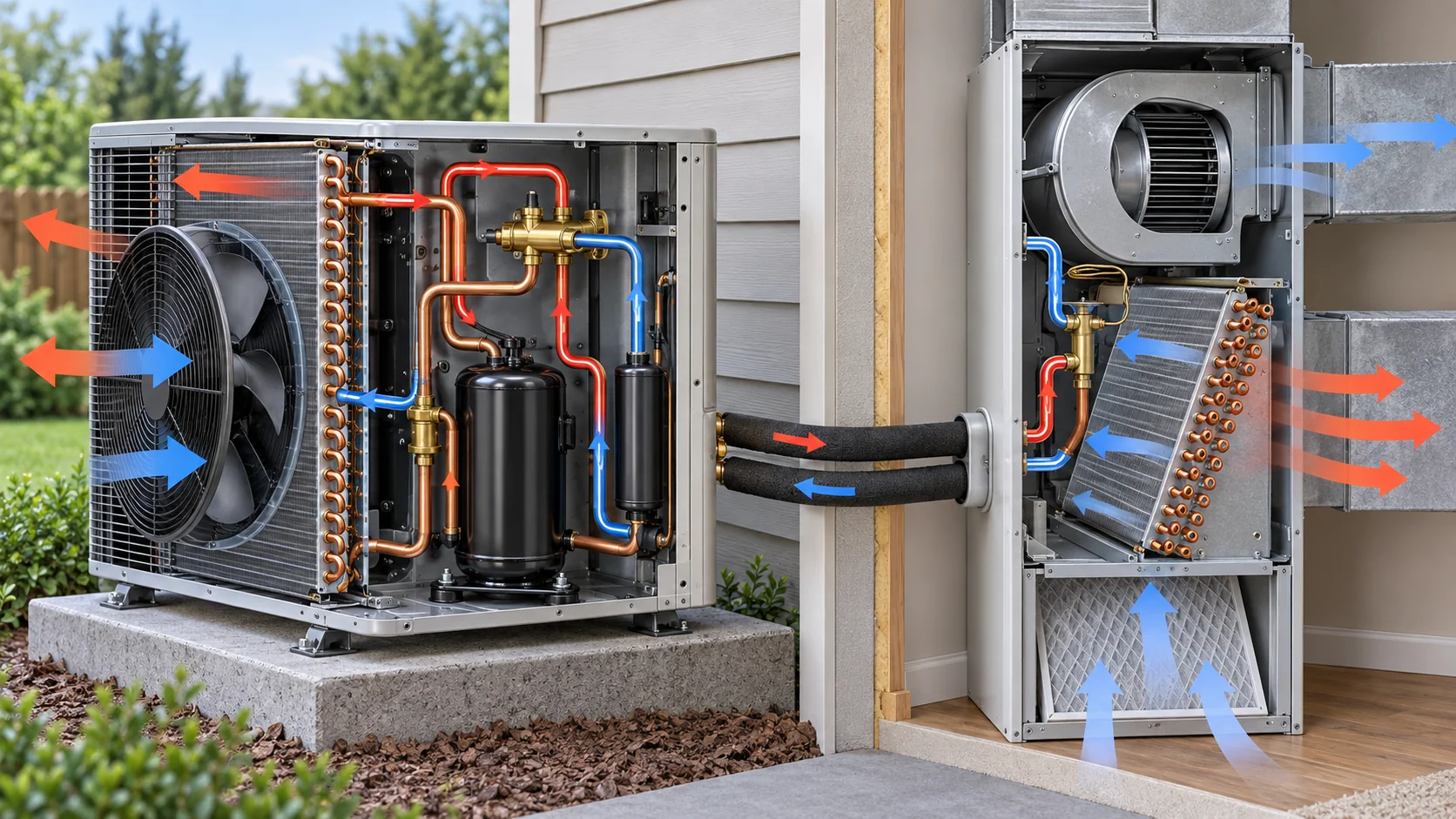
For an equipment manufacturer, “heat pump system” can describe several package boundaries:
- a split air-to-air heat pump with indoor and outdoor coil assemblies;
- a packaged unit with the refrigeration circuit in one cabinet;
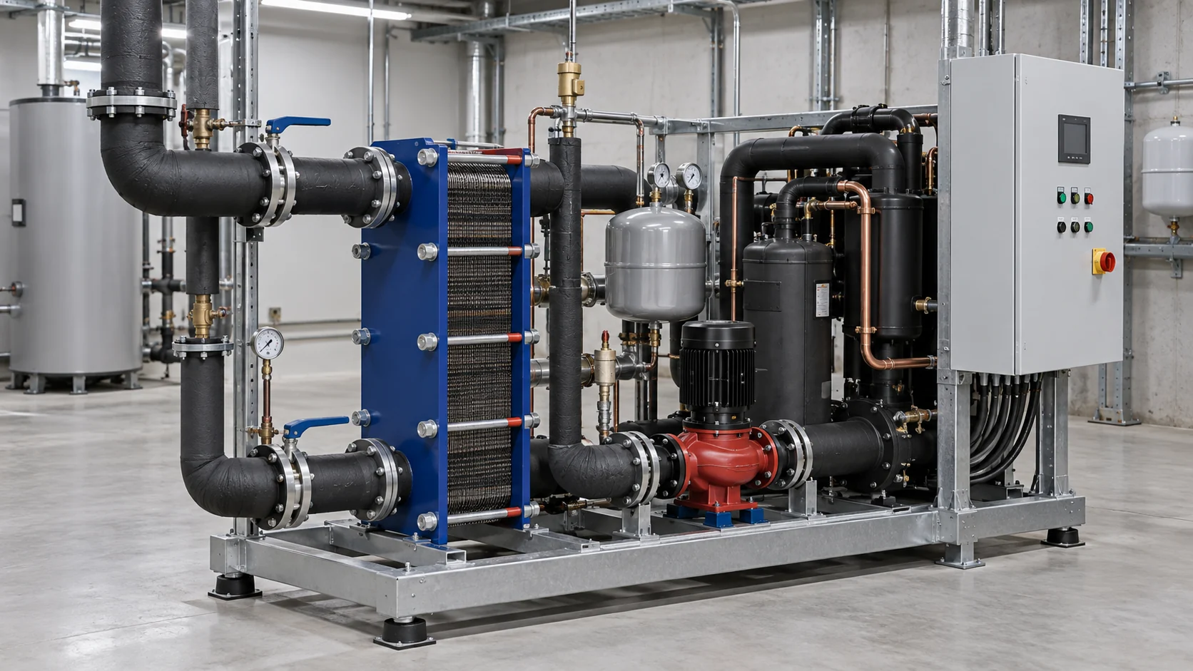
- an air-to-water or water-source heat pump with a refrigerant-to-water heat exchanger;
- a ground-source system with a ground loop and water-side heat exchanger; or
- a larger commercial or industrial heat-recovery package with multiple circuits and controls.
These are not interchangeable designs. A buyer should define the heat source, heat sink, working fluid, capacity condition, and intended operating modes before asking a manufacturer to select a coil geometry.
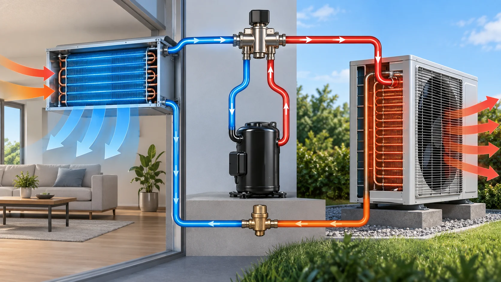
How the heat pump refrigeration circuit works
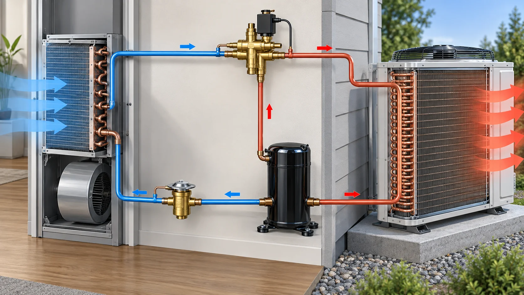
The basic circuit uses a compressor to raise refrigerant pressure, a heat exchanger to reject or absorb heat, an expansion device to reduce pressure, and a second heat exchanger on the other side of the cycle. A reversing valve or another approved flow-control arrangement changes which coil is on the high side and which coil is on the low side when the system changes between heating and cooling.
The visual loop below is a simplified engineering explanation, not a release drawing. The actual circuit may include accumulators, receivers, check valves, oil-management features, economizers, multiple expansion devices, sensors, and parallel circuits.
Heating mode
In heating mode for a typical air-source system, the outdoor coil absorbs heat from outdoor air and operates as the evaporator. The compressor raises the refrigerant pressure and temperature. The indoor coil then releases heat to the indoor air or hydronic loop and operates as the condenser. The fan, coil circuiting, suction and discharge lines, sensors, and controls must work together across the outdoor design range.
Cooling mode
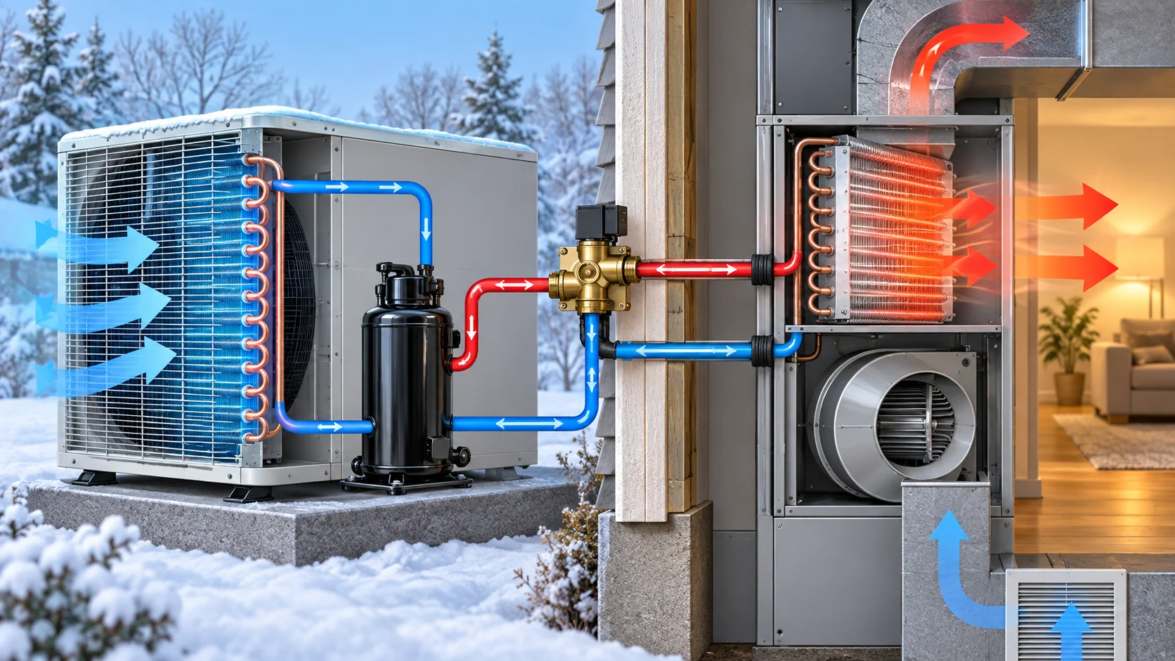
In cooling mode, the flow arrangement changes. The indoor coil absorbs heat from the conditioned space and the outdoor coil rejects that heat to ambient air. The same physical coil may now have a different refrigerant role, saturation condition, condensate behavior, and pressure-drop priority. This mode reversal is the reason a heat-pump coil specification should identify both heating and cooling rating conditions.
Main heat pump system components
The table below is a practical system-boundary checklist for an OEM or equipment integrator. It is intentionally written as a buyer review list, not as a promise that every project uses the same parts.
| Component or interface | Rôle principal | Buyer questions before quotation |
|---|---|---|
| Compresseur | Moves and compresses refrigerant through the circuit | What refrigerant, capacity range, speed control, envelope, oil return, and operating limits apply? |
| Indoor and outdoor heat exchangers | Transfer heat between refrigerant and air, water, glycol, or another approved medium | What are the heating and cooling duties, entering and leaving conditions, airflow or fluid flow, and allowable pressure drop? |
| Reversing valve and check valves | Change the refrigerant path and prevent unwanted reverse flow | Which operating modes, valve interfaces, equalization steps, and control signals must the circuit support? |
| Expansion device or devices | Meter refrigerant and create the pressure drop required by the cycle | Is the design fixed-orifice, thermostatic, electronic, or multi-device, and how will it be controlled in both modes? |
| Fans, pumps, and motors | Move air or secondary fluid across the heat-transfer surfaces | What airflow, water flow, noise, electrical, speed-control, and service-access limits apply? |
| Sensors and controller | Protect the circuit and coordinate capacity, defrost, fan speed, and mode change | Which measured temperatures, pressures, flow states, alarms, and acceptance records are required? |
| Cabinet, piping, drainage, and supports | Make the system installable, serviceable, and safe | What are the connection locations, clearance, condensate path, vibration, corrosion, and packaging constraints? |
In a custom project, the coil is therefore only one part of the system. A coil that fits the cabinet but misses the circuiting, refrigerant distribution, condensate path, or pressure-drop budget can still cause the complete unit to miss its target.
Heat pump system types and when the boundary changes
The source and sink determine the heat exchanger interfaces. They also change the information a supplier needs. For example, an air coil needs airside conditions and an outdoor corrosion or frost strategy, while a water-side heat exchanger needs fluid chemistry, flow, pressure, fouling assumptions, and connection details.
| System type | Heat source or sink | Heat-transfer component to define | Typical selection emphasis |
|---|---|---|---|
| Air-to-air | Outdoor air and indoor air | Outdoor and indoor air coils | Airflow, entering-air condition, frost and drainage, noise, cabinet envelope, and coil circuiting |
| Air-to-water | Outdoor air and a water or glycol loop | Outdoor air coil plus refrigerant-to-water heat exchanger | Water temperature, flow, pump effect, freeze protection, pressure drop, and service access |
| Water-source | A water loop, ground loop, or process loop | Refrigerant-to-water heat exchanger | Fluid chemistry, flow stability, fouling control, working pressure, and approach temperature |
| Ground-source | Ground loop and building-side loop | Ground-loop heat exchanger plus building-side heat exchanger | Ground-loop temperatures, fluid concentration, soil or site data, pressure drop, and long-term maintenance |
| Heat-recovery package | Multiple air or fluid sources and sinks | Multiple coils or heat exchangers | Simultaneous heating/cooling duty, control sequence, load diversity, and operating-mode transitions |
The system type should be decided before choosing between microchannel, fin-tube, shell-and-tube, brazed-plate, or another heat-transfer architecture. Domi’s HVAC and heat-pump solutions page is the commercial starting point for discussing custom heat-transfer components; it does not replace a project-specific rating or responsible engineer’s design.
Choosing a heat pump coil architecture
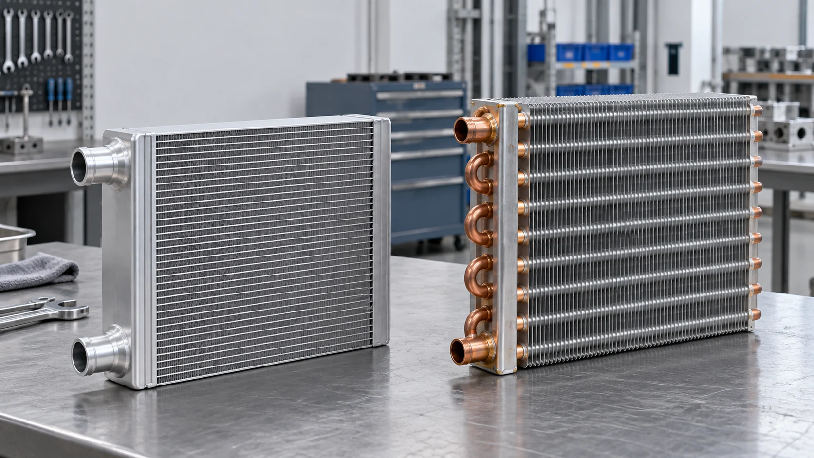
For air-source heat pumps, two common air-coil families are compact aluminum microchannel cores and copper-tube aluminum fin-tube cores. Neither is automatically the right answer. The decision depends on the refrigerant, design pressure, circuiting, airflow, corrosion exposure, service expectations, manufacturing method, available package depth, and the buyer’s validation plan.
Microchannel heat pump coils
Microchannel coils can provide a compact core and a low material volume for some air-cooled designs. They require careful header, port, circuit, brazing, and pressure review. The supplier should also review cleaning access, corrosion environment, condensate behavior, repair expectations, and the selected refrigerant before treating a microchannel design as a drop-in replacement.
Fin-tube heat pump coils
Fin-tube coils are familiar in many HVAC and refrigeration applications and can offer flexible tube, fin, header, and circuiting choices. They may be a practical path when the project needs a particular connection layout, repair approach, sample-to-production transition, or replacement fit. Fin spacing, tube expansion, circuit balance, and the airside pressure-drop limit remain project-specific.
For a deeper construction comparison, see Microcanal contre serpentins à ailettes pour les systèmes CVC. If a project only has a cabinet drawing or old sample, the custom HVAC coil sizing guide explains why dimensions alone are not a complete rating input.
Heat pump system inputs needed for a custom coil quote
The most useful RFQ data describes the operating envelope rather than only the requested face dimensions. Ranges are acceptable for an early review when they are clearly marked as preliminary.
| Groupe d’entrée | Exemples à fournir | Why it changes the design |
|---|---|---|
| Charge thermique | Heating capacity, cooling capacity, sensible/latent split, design entering and leaving conditions | Sets the required heat-transfer area, circuiting, and rating points |
| Airside conditions | Airflow, entering dry-bulb and wet-bulb temperature, humidity, face velocity, filter condition | Controls airside pressure drop, condensation, frost risk, and fan selection |
| Côté fluide ou côté fluide frigorigène | Refrigerant or secondary fluid, mass flow, saturation or entering/leaving temperatures, design pressure | Determines tube, header, plate, material, circuit, and safety review requirements |
| Enveloppe mécanique | Width, height, depth, connections, orientation, service clearances, drain location, mounting points | Prevents a thermally suitable core from failing the cabinet or installation fit |
| Mode and control range | Heating and cooling points, defrost sequence, fan control, capacity modulation, ambient range | Ensures one physical assembly is reviewed across its complete duty cycle |
| Environnement | Outdoor exposure, salt or chemical exposure, cleaning method, humidity, dust, vibration | Influences fin treatment, material, coating, drainage, and protective packaging |
| Validation target | Sample quantity, test method, pressure/leak checks, airflow or thermal evidence, inspection records | Defines how the design will be approved before production release |

The buyer should separate “known,” “estimated,” and “to be confirmed” values. A supplier can review a preliminary envelope, but a final selection normally requires the responsible system engineer to confirm the load calculation, applicable safety requirements, controls, and complete equipment rating.
Performance, defrost, condensate, and control checks
Heat pump performance is a system result. Coil geometry, compressor map, expansion control, fan or pump power, refrigerant charge, airflow, water flow, control logic, and installation condition all affect the result. A catalog capacity from one mode should not be treated as proof of the other mode.
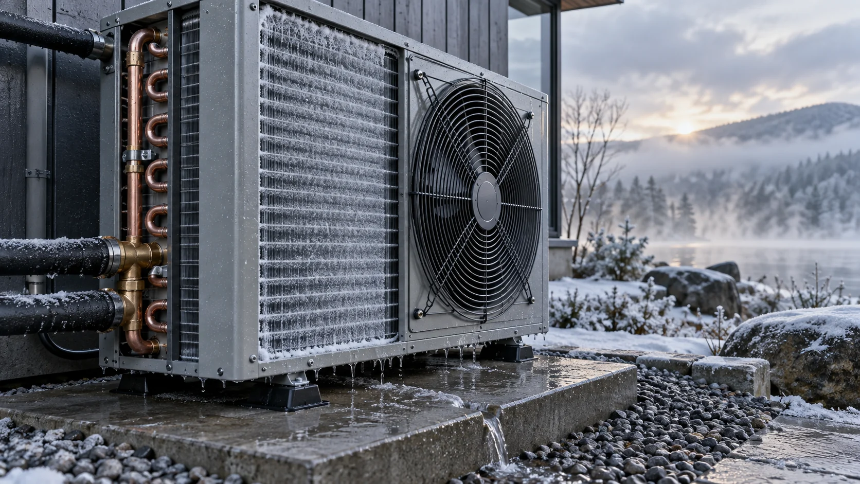
Outdoor air coils deserve extra review in heating mode. Frost may restrict airflow and reduce heat transfer; the system then needs a suitable defrost sequence, valve and fan coordination, temperature or pressure sensing, and a controlled path for meltwater. The coil design should also prevent water from refreezing in a location that blocks airflow or damages the cabinet. Domi’s specialist guide on heat pump outdoor coil frosting and defrost design covers those controls and OEM checks in more detail.
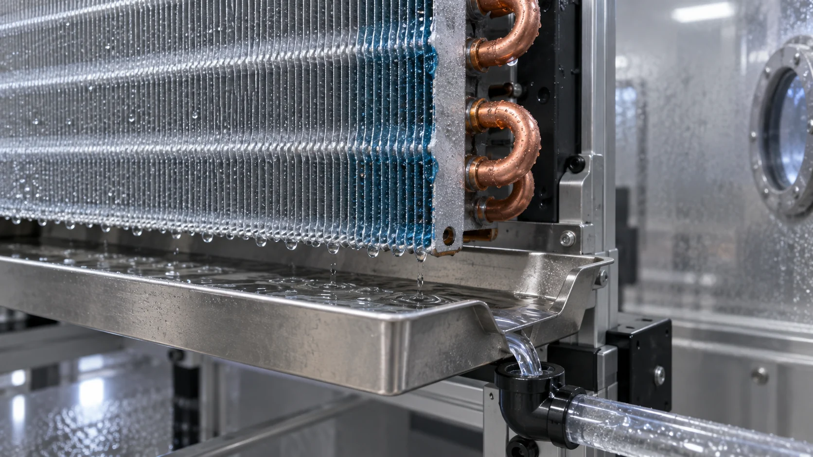
Condensation matters in cooling mode as well. The indoor coil may collect water, and the outdoor coil may collect meltwater after defrost. A coil quote should identify drain-pan geometry, slope, outlet position, material compatibility, installation orientation, and the customer’s cleaning or freeze-protection approach.
Refrigerant, materials, and compliance boundaries
The selected refrigerant is a design input, not a late-stage label. Refrigerant properties, operating pressure, oil compatibility, temperature glide where applicable, charge limits, connection method, and applicable market or safety requirements can change the coil and circuit review. A coil designed for one refrigerant should not be assumed to be suitable for another without engineering review and validation.
Materials also need context. Copper tube and aluminum fin construction, aluminum microchannel, stainless components, coated surfaces, brazed-plate heat exchangers, and other architectures each have different corrosion, joining, pressure, cleaning, and service considerations. The right material decision depends on the actual fluid, air environment, operating pressure, temperature, production method, and acceptance criteria.
For applicable unitary air-source heat pumps, AHRI publishes a 210/240 performance rating standard covering definitions, test and rating requirements, and minimum published rating information. AHRI also explains a unitary heat pump certification program that includes matched coils. These references help define a rating boundary; they should not be read as a claim that every custom coil or supplier project is certified under those programs.
Testing and validation before production release
A useful validation plan connects each risk to a measurement or inspection record. Depending on the project, the review may include:
- visual and dimensional inspection against an approved drawing;
- pressure or leak testing using the agreed medium, fixture, duration, and acceptance limit;
- airflow and pressure-drop review at specified conditions;
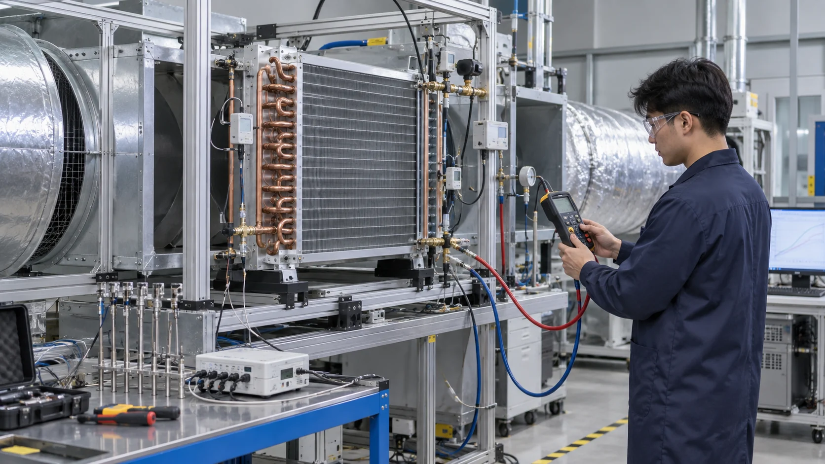
- heat-transfer or capacity testing at heating and cooling rating points;
- condensate and defrost drainage observation;
- corrosion or coating evaluation for the stated environment;
- material, tube, header, fin, brazing, and traceability records; and
- sample approval with controlled drawing revision and change management.
The acceptance method must be agreed before a sample is made. “Tested” is not enough for an RFQ unless the buyer and supplier share the test point, equipment, method, tolerance, and evidence format. Domi’s laboratoire d’essais d’échangeurs de chaleur page describes the available project-discussion route for airflow, corrosion, pressure safety, leakage, and performance documentation; the actual scope remains subject to project confirmation.
Manufacturing and supplier review
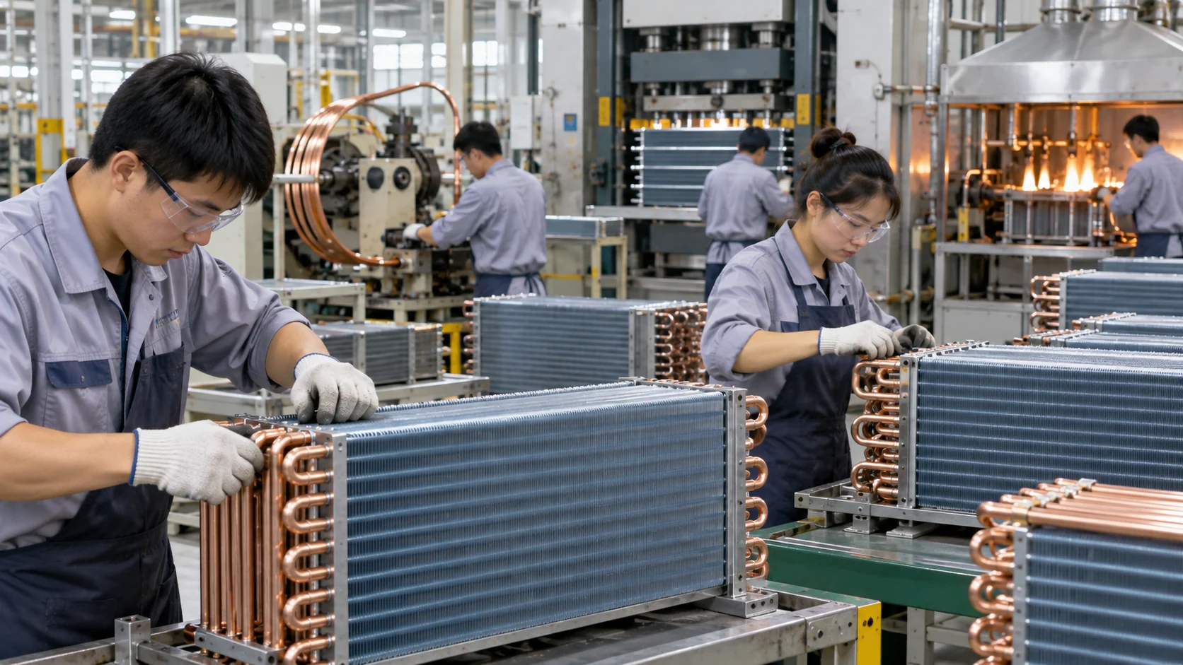
After the design is accepted, the production review should focus on repeatability rather than only the first sample. Ask how the supplier will control tube and fin dimensions, header position, circuiting, brazing or joining, leak checks, coating application, drain-pan fit, packaging, and revision status. The best evidence is tied to the drawing and the released inspection plan.
Domi describes its l'ingénierie thermique et au support CFD de Domi as a route for requirement review, calculation, simulation support, material selection, sample development, and validation guidance. Buyers should still confirm which calculations, tests, reports, materials, and production controls are included in their own quotation.
Heat pump coil RFQ checklist
The following checklist can be sent with a drawing, old sample photo, cabinet envelope, or parameter sheet. It is better to send an imperfect but clearly marked brief than to hide missing operating data.
| Article de demande de prix | Minimum useful information | Approval evidence to request |
|---|---|---|
| Application and operating modes | Equipment type, source and sink, heating/cooling sequence, ambient or water range | Agreed rating-point summary and mode matrix |
| Capacity and flow | Heating/cooling duty, airflow or fluid flow, entering and leaving temperatures, humidity where relevant | Calculation basis, performance report, or agreed estimate status |
| Réfrigérant ou fluide secondaire | Fluid name, pressure range, temperature range, concentration, chemistry, and safety constraints | Material and pressure suitability review |
| Geometry and interfaces | Core dimensions, tube/header layout, connection size/location, mounting, drain, clearance, orientation | Controlled drawing with revision and fit check |
| Environment and finish | Outdoor exposure, salt, chemicals, cleaning, corrosion class, coating or treatment request | Material/coating statement and sample inspection |
| Qualité et validation | Leak/pressure test, airflow, capacity, corrosion, dimensional, packaging, and traceability requirements | Inspection plan, test record, and sample sign-off path |
| Commercial boundary | Prototype quantity, production quantity, target schedule, packaging, shipping, and documentation | Quote assumptions and confirmed exclusions |

If some data is not available, state the uncertainty. A supplier can help recover missing information from an old coil, nameplate, sample photo, cabinet drawing, or test record, but the final responsibility for the complete system design and compliance remains with the equipment owner and responsible engineer.
How to turn the brief into a supplier conversation
An efficient technical conversation usually follows this order:
- Define the system boundary and which components are in the supplier’s scope.
- Confirm the two operating modes and the rating conditions for each mode.
- Identify the refrigerant or secondary fluid and the pressure, temperature, and material constraints.
- Compare coil architectures against the package, airflow, corrosion, service, and production requirements.
- Agree the drawing, sample, test, inspection, packaging, and revision-control evidence.
- Separate preliminary assumptions from the final data required for release.
This sequence reduces the risk of receiving a price for a physically similar coil that cannot meet the complete heat-pump system requirement. To start a component review, use Demander un devis pour un serpentin sur mesure or contact the Domi engineering team. Send the drawing, old sample photo, operating envelope, or parameter sheet that is available.
Questions fréquemment posées
What are the main components of a heat pump system?
A typical heat pump system includes a compressor, indoor and outdoor heat exchangers, expansion device or devices, reversing valve where reversible operation is required, fans or pumps, sensors, controls, piping, supports, drainage, and a cabinet or installation interface. The exact list changes with the air-to-air, air-to-water, water-source, ground-source, or heat-recovery configuration.
What is the difference between a heat pump condenser and evaporator coil?
The names describe the coil’s refrigerant role at a particular operating condition. In a typical heating mode, the outdoor coil acts as the evaporator and the indoor coil acts as the condenser. In cooling mode, the roles reverse. A heat-pump coil specification should therefore show both mode conditions instead of assigning one permanent name to the physical coil.
How should I size a heat pump coil?
Start with the heating and cooling duty, entering and leaving air or fluid conditions, airflow or mass flow, refrigerant or secondary fluid, allowable pressure drop, mechanical envelope, connections, environment, and validation target. A face dimension or nominal tonnage can support an early discussion but is not a complete custom-coil rating input.
Can a custom heat pump coil be designed from an old sample?
Often, an old sample, photo, drawing, or nameplate can start the review. The supplier should recover dimensions, connection locations, material clues, circuiting, operating conditions, and the intended replacement fit, then identify which values still need confirmation. The sample should be treated as evidence to verify, not as proof that the old design meets the new system duty.
What should be included in a heat pump coil RFQ?
Include the application, heating and cooling rating points, capacity, airflow or fluid flow, entering and leaving conditions, refrigerant or secondary fluid, pressure and temperature range, dimensions, connections, drainage, materials, corrosion environment, controls or defrost constraints, sample quantity, test requirements, packaging, schedule, and documentation expectations. Mark estimated or missing values so the quote assumptions remain visible.
Does Domi supply complete heat pump systems?
Domi’s public offering is focused on custom heat exchangers, HVAC and refrigeration coils, thermal engineering support, sample development, and testing discussions. A project can be reviewed from a drawing, old sample, or parameter sheet, but the quotation should define whether the scope is a coil, heat exchanger, subassembly, testing support, or another component. Complete-system design, certification, installation, and final performance responsibility must be confirmed for the specific project.
Request a reviewable heat pump coil quote
The fastest useful next step is to send the information that defines the system boundary: application, heating and cooling duty, operating temperatures, airflow or fluid flow, refrigerant or secondary fluid, mechanical envelope, connections, drainage, environment, and validation target. Domi can then review whether the request is ready for a custom coil discussion, what assumptions remain, and which sample or test evidence should be planned.
Demander un devis personnalisé · Envoyez votre dessin pour révision · Review Thermal Engineering Support