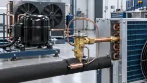
The refrigerant cycle is a closed loop where refrigerant absorbs heat in the evaporator, is pressurized by the compressor, rejects that heat in the condenser, then drops pressure at the metering device — repeating continuously to move heat out of a cooled space.
Most explanations of the refrigerant cycle stop at four arrows on a diagram. That is fine if you only need to pass an exam. It is not enough if you are specifying a condenser coil for a walk-in freezer, troubleshooting a fridge that won’t pull down, or deciding whether R290 makes sense for your next appliance batch.
We build condenser and evaporator coils for a living. So this guide walks the refrigerant cycle the way an engineer actually thinks about it: what happens to pressure, temperature, and the physical state of the refrigerant at every point — and where the coil you choose makes or breaks the whole thing.
By the end you’ll be able to trace refrigerant through all four stages, read what the pressures and temperatures should be at each point, calculate superheat and subcooling, and understand why two systems with the same compressor can cool very differently. That last part is where component selection lives, and it’s the part most explainers ignore entirely.
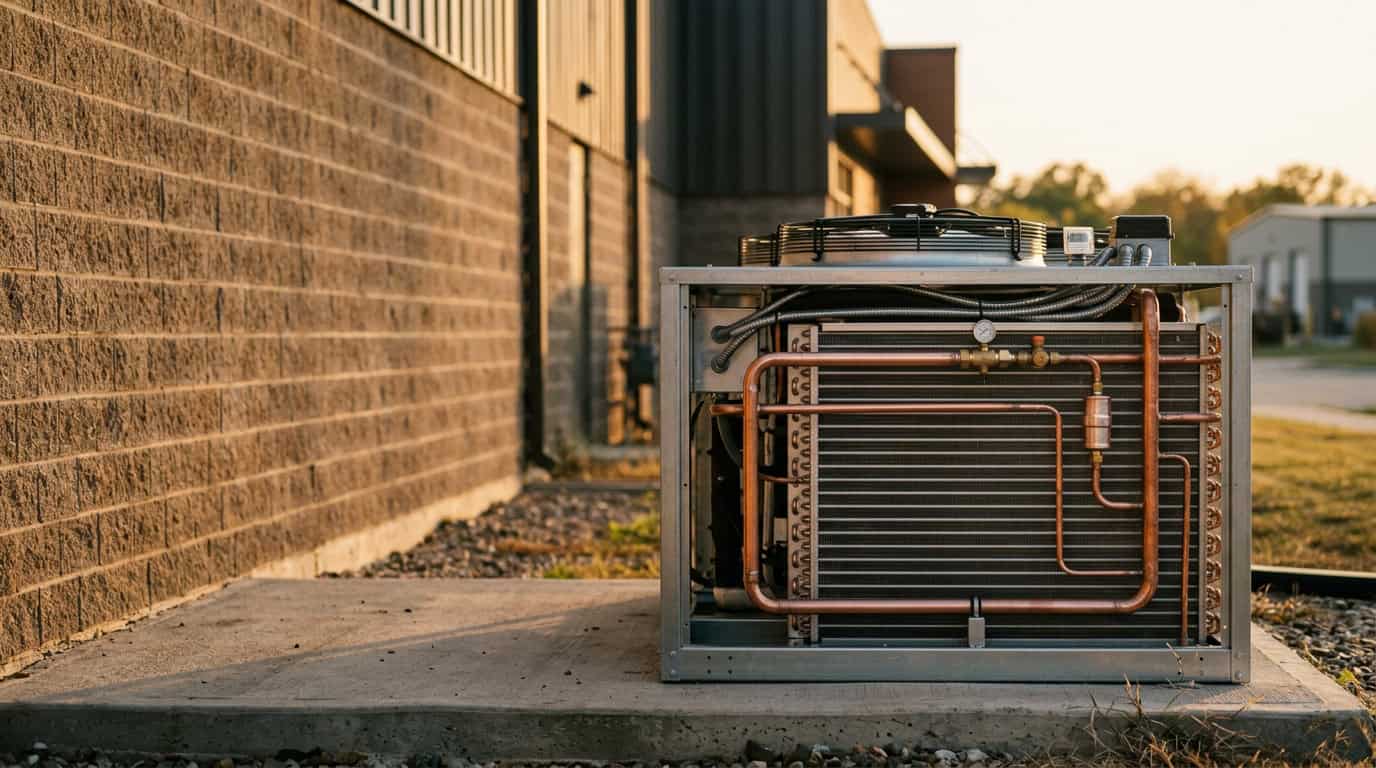
What Is the Refrigerant Cycle?
The refrigerant cycle moves heat from a cold space to a warm one using a fluid that changes state. That is the whole trick. Heat naturally flows from hot to cold, so to pump it “uphill” you need a working fluid and a compressor doing work on it.
The closed-loop principle
A refrigerant never gets used up. It circulates through the same sealed circuit thousands of times an hour, switching between liquid and vapor. When it boils (evaporates), it swallows heat. When it condenses, it dumps that heat. The compressor and metering device set the pressures that decide where in the loop each of those phase changes happens.
This is why people also call it the vapor-compression refrigeration cycle. As the engineering reference at Wikipedia’s heat pump and refrigeration cycle article lays out, the same four-component loop powers your refrigerator, a supermarket display case, and a 500-ton chiller — only the scale and refrigerant change.
Why phase change moves so much heat
Here’s the part that makes the whole refrigerant cycle worth the trouble: boiling a liquid absorbs far more heat than simply warming it. The energy that turns liquid into vapor, called latent heat, dwarfs the energy needed to raise the same fluid’s temperature by a few degrees. For water that ratio is enormous, and refrigerants exploit the same physics with fluids tuned to boil at useful low temperatures.
That is why the evaporator works by boiling refrigerant rather than just letting cold fluid flow past warm air. A coil that boils a kilogram of refrigerant moves many times the heat it could move by sensible warming alone. Get the refrigerant to change state at the right pressure and you get a small coil doing a big cooling job. Fail to fully boil it (because the metering device starves the coil, or because the coil is undersized) and capacity collapses even though refrigerant is still flowing.
High side vs low side
Every refrigerant cycle splits into two pressure zones. The high side runs from the compressor discharge through the condenser to the metering device. The low side runs from the metering device outlet through the evaporator back to the compressor suction. Knowing which side a component sits on tells you what pressure and temperature to expect there — and that is the foundation of every diagnosis you will ever make.
Here is the cycle at a glance before we open each stage:
| Stage | Component | Refrigerant state in → out | Pressure | Heat |
|---|---|---|---|---|
| Compression | Compressor | Low-P vapor → high-P vapor | Rises | Work added |
| Condensation | Condenser coil | High-P vapor → high-P liquid | High (steady) | Rejected |
| Expansion | Metering device | High-P liquid → low-P mix | Drops sharply | None |
| Evaporation | Evaporator coil | Low-P mix → low-P vapor | Low (steady) | Absorbed |
The 4 Stages of the Refrigerant Cycle
The refrigerant cycle has four stages: compression, condensation, expansion, and evaporation. Each one hands the refrigerant to the next in a specific state, and a fault in one stage shows up as wrong numbers in another.
Stage 1 — Compression
The compressor pulls in low-pressure, low-temperature vapor and squeezes it into high-pressure, high-temperature vapor. No heat is removed here — compression just raises the refrigerant’s pressure and temperature so it is hot enough to reject heat to outdoor air later. A typical R134a system might leave the evaporator around 5 °C and exit the compressor at 70–80 °C. That temperature jump is the compressor doing its job.
The thing spec sheets rarely stress: the compressor must only ever see vapor. Liquid refrigerant returning to the suction line (called flooding) can wreck a compressor in minutes because liquids don’t compress. This single rule shapes the rest of the cycle: every design choice downstream exists partly to guarantee the refrigerant arrives back at the suction port fully boiled.
Compressor type matters too. Reciprocating compressors suit higher pressure ratios; scroll compressors run quieter and smoother for mid-size commercial work; small sealed appliances use hermetic compressors where the motor and pump share one welded shell. The cycle is identical across all of them — only the pumping hardware changes.
Stage 2 — Condensation
Hot high-pressure vapor enters the condenser coil and rejects heat to the surrounding air (or water). As it cools, it condenses back into a high-pressure liquid. This is where a coil maker earns their keep: condensing capacity depends on surface area, fin density, airflow, and tube circuiting. Undersize the condenser and head pressure climbs, efficiency falls, and the compressor runs hot.
Condensation actually happens in three zones along the coil: a short desuperheating zone where the hot vapor cools to its condensing temperature, a long condensing zone where it changes phase at near-constant temperature, and a final subcooling zone where the liquid drops a few more degrees. A well-built condenser coil gives each zone the surface area it needs. Skimp on the subcooling zone and you feed flash gas to the metering device, which chokes the evaporator downstream.
Field tip: A condenser caked in dust behaves exactly like an undersized one. We’ve measured head-pressure rises of 20–30% on neglected units before any component had actually failed — the coil just couldn’t breathe.
Stage 3 — Expansion
The high-pressure liquid hits the metering device (capillary tube, thermostatic expansion valve, or electronic valve) and its pressure drops sharply. A small fraction flashes to vapor immediately, which chills the remaining liquid to the low evaporating temperature. Nothing is added or removed — this stage simply sets up the low-pressure, cold mixture the evaporator needs.
Stage 4 — Evaporation
The cold low-pressure mixture enters the evaporator coil, where it absorbs heat from the space being cooled and boils into vapor. This is the stage that actually does the cooling you care about. The vapor then heads back to the compressor and the refrigerant cycle starts over. Pick the wrong evaporator and you get frost, uneven temperatures, or a box that never reaches setpoint.
Two failure modes haunt the evaporator. Frosting happens when the coil runs below freezing and water vapor builds ice that insulates the fins — which is why freezer evaporators need a defrost strategy baked into the design. Liquid carryover happens when the coil can’t fully boil the refrigerant, sending wet vapor to the compressor. The fix for both starts at the coil: the right surface area, fin spacing, and refrigerant distribution for the actual operating temperature.
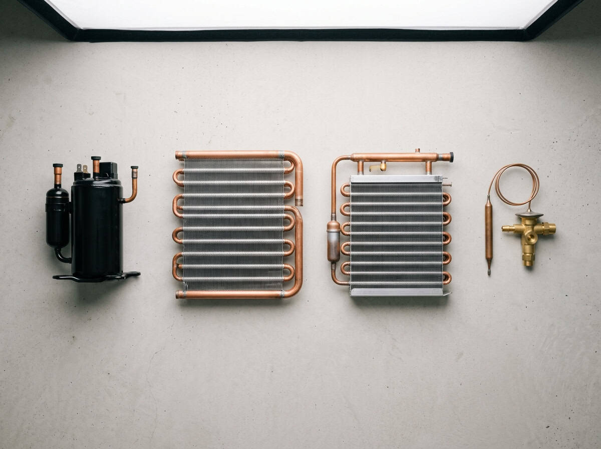
Here is what happens to the refrigerant at each stage of a typical R134a system:
| Point in cycle | State | Pressure (approx) | Temperature (approx) |
|---|---|---|---|
| Compressor suction | Superheated vapor | Low (~2 bar) | ~10 °C |
| Compressor discharge | Hot vapor | High (~14 bar) | ~75 °C |
| Condenser outlet | Subcooled liquid | High (~14 bar) | ~45 °C |
| Evaporator inlet | Liquid/vapor mix | Low (~2 bar) | ~0 °C |
| Evaporator outlet | Superheated vapor | Low (~2 bar) | ~5 °C |
Values vary with refrigerant, ambient conditions, and load — treat them as a mental model, not a setpoint.
Pressure, Temperature, Superheat & Subcooling
Superheat and subcooling are the two numbers that tell you whether the refrigerant cycle is actually healthy. Most guides skip them. They shouldn’t.
What superheat tells you
Superheat is how many degrees the vapor leaving the evaporator sits above its boiling (saturation) temperature at that pressure. A little superheat is good — it guarantees only dry vapor reaches the compressor. Too much superheat means the evaporator is starved of refrigerant; too little (or zero) means liquid is flooding back. We’ve found that getting superheat into the right band fixes more “weak cooling” complaints than any parts swap.
What subcooling tells you
Subcooling is the mirror image on the high side: how many degrees the liquid leaving the condenser sits below its condensing temperature. Healthy subcooling confirms the condenser fully condensed the refrigerant and is feeding solid liquid to the metering device. Low subcooling often points to undercharge or a struggling condenser coil.
A worked example
Say you’re checking an R134a system. The low-side gauge reads a pressure whose saturation temperature is 2 °C, and the suction line measures 9 °C. Your superheat is 9 − 2 = 7 °C — a healthy figure, dry vapor heading to the compressor. Now the high side: the gauge saturation temperature is 48 °C, and the liquid line measures 42 °C. Subcooling is 48 − 42 = 6 °C — the condenser is doing its job. Two subtractions, and you already know both ends of the cycle are behaving. If that superheat had read 20 °C instead, you’d suspect a starved evaporator or undercharge long before touching anything.
Both numbers live on the pressure-enthalpy (P-h) diagram, the chart engineers use to map the whole refrigerant cycle. The vertical axis shows pressure, the horizontal axis shows heat content (enthalpy), and the cycle traces a rough rectangle around the saturation dome. Compression pushes the refrigerant up and to the right; condensation runs left across the top as heat leaves; expansion drops straight down at constant enthalpy; evaporation runs right across the bottom as heat comes in. The horizontal width of that bottom line is your cooling capacity per kilogram of refrigerant.
You don’t need to draw one daily, but the diagram explains why two systems with identical compressors can have very different capacity: the refrigerant and the coil temperatures decide how wide that evaporation line stretches. It also makes superheat and subcooling visual — small horizontal stubs sticking out past the saturation dome on each side. Once you can picture the cycle as a shape rather than four arrows, diagnosis gets a lot more intuitive.
Refrigerant Types and How They Change the Cycle
Different refrigerants run the same four-stage cycle at very different pressures and temperatures. The choice drives compressor design, coil sizing, safety class, and increasingly, legality.
The big shift over the last decade has been away from high-GWP (global warming potential) refrigerants toward lower-GWP and natural options. The US EPA’s refrigerant management program and the global HFC phasedown have pushed appliance makers toward R290 (propane) and R600a (isobutane) in small sealed systems, and R32 or R454B in larger equipment.
| Refrigerant | Type | GWP (approx) | Typical use | Note |
|---|---|---|---|---|
| R134a | HFC | ~1,430 | Older fridges, auto A/C | Being phased down |
| R410A | HFC blend | ~2,088 | Residential A/C | High pressure, phasing out |
| R32 | HFC | ~675 | New split A/C | Mildly flammable (A2L) |
| R290 | Natural (propane) | ~3 | Small commercial, fridges | Flammable, charge-limited |
| R600a | Natural (isobutane) | ~3 | Household refrigerators | Flammable, low charge |
| R744 | Natural (CO₂) | 1 | Supermarkets, transport | Very high pressure |
Safety classification is the other half of the decision. Refrigerants carry an ASHRAE safety class combining toxicity and flammability: A1 is non-flammable (R134a, R410A), A2L is mildly flammable (R32, R454B), A3 is highly flammable (R290, R600a), and B classes flag higher toxicity (ammonia is B2L). The flammable classes are perfectly safe in correctly designed, charge-limited systems — but they dictate maximum charge, ventilation, electrical components, and how the coil circuit is built. You cannot pick a refrigerant for its low GWP and ignore what its safety class demands of the hardware.
For appliance and OEM projects, the refrigerant decision can’t be separated from the hardware. R290 and R600a run at low charges and need coils designed for small internal volume — exactly the kind of work that flows through our custom coil fabrication line. CO₂ systems, by contrast, demand coils and tubing rated for transcritical pressures several times higher than an R134a circuit.
How Condenser & Evaporator Coils Shape Cycle Performance
The coils are where the refrigerant cycle meets the real world — they set how much heat actually moves, so coil design directly caps system efficiency.
You can pair a perfect compressor with the perfect refrigerant and still get a mediocre system if the coils are wrong. Two-thirds of the cycle’s heat transfer happens inside the coils, so their geometry decides your real-world capacity.
Condenser coil design
A condenser coil has to reject all the heat the evaporator absorbed plus the heat the compressor added. That is why condensers are usually larger than evaporators in the same system. Fin spacing matters: tight fins add surface area but clog faster and resist airflow. We generally open up fin density on units headed for dusty or greasy environments, trading a little lab-rated capacity for capacity that survives a year in the field.
Evaporator coil design
An evaporator coil has the opposite problem — it has to absorb heat at low temperature without frosting solid or starving the compressor of return vapor. Circuit count, tube diameter, and refrigerant distribution all decide whether the coil floods, starves, or runs clean. Roll-bond and fin-type evaporators each suit different cabinet shapes, which is why coil selection always comes back to the actual equipment.
Tube and fin material
Coil performance also rides on materials. Copper-tube/aluminum-fin remains the workhorse for its balance of conductivity, formability, and cost. All-aluminum and microchannel coils save weight and refrigerant charge, which matters more every year as flammable low-charge refrigerants spread. For corrosive coastal or chemical environments, coatings or alternative alloys buy years of service life. None of this changes the four stages of the refrigerant cycle — but it changes how long your hardware keeps running them reliably.
Expert tip: When a system underperforms, check coil cleanliness and airflow before you ever touch the charge. A blocked coil mimics almost every refrigerant fault on the gauges.
Refrigerant Cycle by Application: Residential, Commercial & Industrial
The four-stage refrigerant cycle is identical across applications; what changes is scale, refrigerant, and duty. The hardware gets very different.
- Residential — Household refrigerators and small A/C use sealed systems, capillary tubes or small valves, and low charges of R600a or R290. Reliability and quiet operation rule. These are the kinds of compact coils covered by our residential refrigeration coils range.
- Commercial — Supermarkets, restaurants, and cold rooms run larger condensing units, thermostatic or electronic valves, and often multiple evaporators on one rack. Defrost strategy and pull-down speed dominate the design.
- Industrial — Cold storage, process cooling, and large chillers may use ammonia, CO₂, or flooded evaporators with pumped refrigerant. Here the refrigerant cycle is engineered around efficiency at huge duty and continuous run hours. A single percentage point of efficiency translates into real money when a plant runs every hour of the year, so industrial design obsesses over condensing temperature, subcooling, and heat recovery in ways a household fridge never bothers with.
The practical takeaway across all three: the cycle is the same, but you cannot lift a residential coil into a commercial duty and expect it to hold. Surface area, circuiting, defrost, and refrigerant compatibility all have to match the application — which is exactly why coil selection is an engineering conversation, not a catalog pick.
A “refrigerant cycle in a chiller” is a common search for good reason: chillers add a water loop on top of the basic cycle, using the evaporator to chill water that then circulates through the building. As Britannica’s overview of refrigeration notes, the same vapor-compression principle scales from a domestic icebox to industrial process cooling. The core four stages don’t change — they just hand their cooling to water instead of air.
Metering Devices & Common Cycle Problems
The metering device controls refrigerant flow into the evaporator, and most refrigerant cycle faults trace back to flow, charge, or airflow problems.
Capillary vs TXV vs EEV
There are three common metering devices, and the right one depends on how variable the load is:
- Capillary tube — a fixed-bore copper tube. Cheap, no moving parts, ideal for sealed appliances with steady load. It can’t adjust to changing conditions, so charge has to be exact.
- Thermostatic expansion valve (TXV) — modulates flow to hold a target superheat. Standard on commercial systems with variable load.
- Electronic expansion valve (EEV) — a stepper-motor valve driven by a controller. Most precise, supports variable-speed compressors and the tight control modern efficiency standards demand.
The faults that actually show up
When a refrigerant cycle misbehaves, the usual suspects are predictable:
- Undercharge — low pressures both sides, high superheat, weak cooling.
- Overcharge — high head pressure, low subcooling room, risk of flooding.
- Restricted metering device — high subcooling, low evaporator pressure, frost at the restriction.
- Dirty condenser — high head pressure, high discharge temp (covered above).
- Non-condensables (air) in the system — abnormally high head pressure for the conditions.
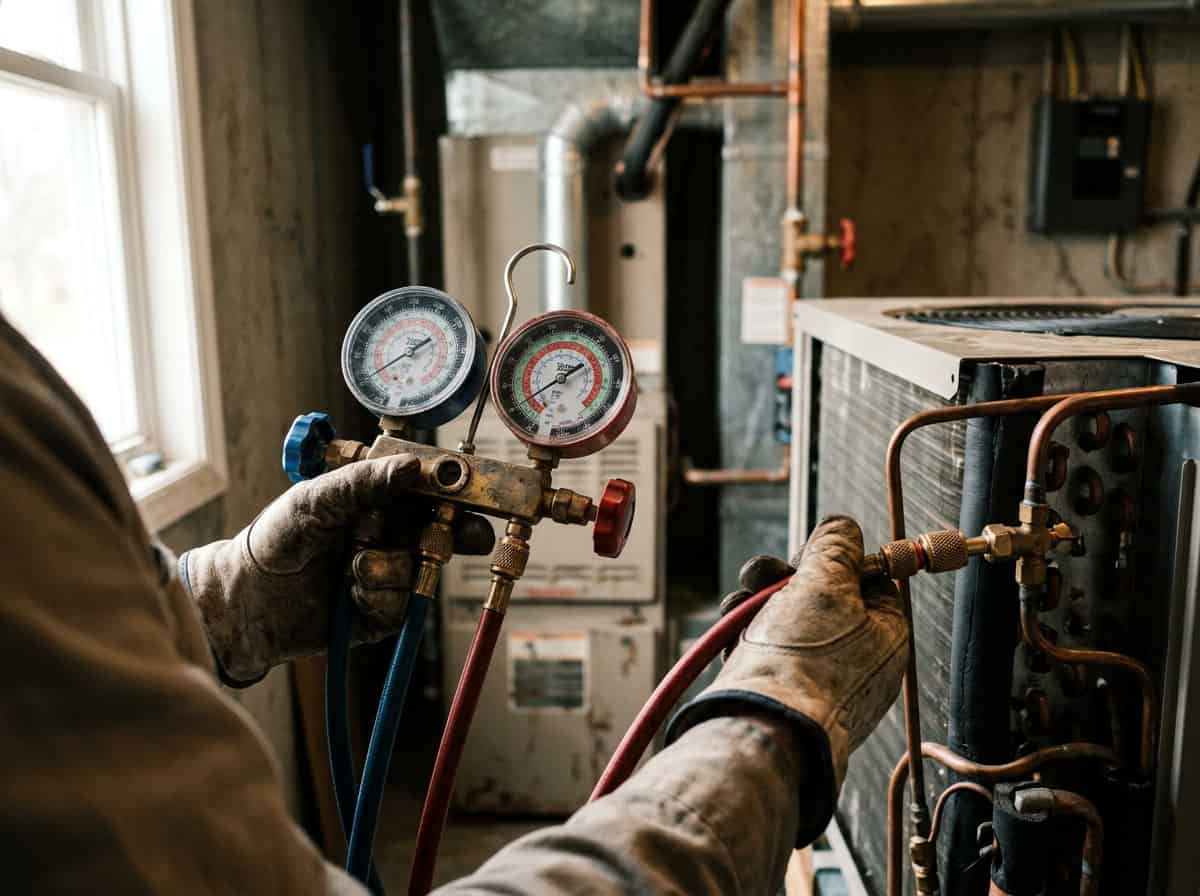
Here’s the order we actually work a no-cool call, and it rarely fails us:
- Look and listen first. Is the condenser fan running? Is the coil filthy? Is there airflow across the evaporator? Half of “refrigerant” complaints die right here.
- Connect the manifold and read both pressures. Convert each to its saturation temperature for the refrigerant in the system.
- Measure suction-line and liquid-line temperatures, then calculate superheat and subcooling.
- Compare against targets for the equipment and conditions. The two numbers, read together, point at undercharge, overcharge, restriction, or airflow before you’ve opened anything.
- Only then decide whether to adjust charge, clean a coil, or change a component.
The discipline that saves you: read both pressures, calculate superheat and subcooling, then form a theory. Charging by gauge pressure alone is how good refrigerant gets dumped into a system that never needed it.
Future Trends (2026 & Beyond)
The refrigerant cycle itself won’t change, but the refrigerants and controls running it are shifting fast toward lower environmental impact and tighter efficiency.
Three forces are reshaping the field as of early 2026:
- Low-GWP and natural refrigerants keep gaining share as HFC quotas tighten. Propane (R290) charge limits were raised in recent standards updates, opening it to larger equipment.
- Variable-speed everything — inverter compressors and EEVs let the cycle match capacity to load instead of cycling on and off. The US Department of Energy’s guidance on heat pump systems ties this kind of modulating operation to meaningful efficiency gains over fixed-speed equipment.
- Microchannel and high-efficiency coils pack more surface area into less aluminum, improving the heat-transfer end of the cycle.
| Trend | What’s driving it | Impact on the cycle |
|---|---|---|
| Natural refrigerants (R290, R600a, CO₂) | HFC phasedown, GWP rules | Low charge, higher pressures, coil redesign |
| Inverter / variable-speed | Efficiency standards | Cycle modulates instead of on/off |
| EEV adoption | Precise superheat control | Tighter, more stable operation |
| Microchannel coils | Material cost, performance | Higher heat transfer per gram of metal |
A fourth force is quieter but real: monitoring. Connected systems now log suction and discharge pressures, superheat, and subcooling continuously, flagging a drifting refrigerant cycle before it trips out. That turns the diagnostic discipline we described earlier into something a controller watches around the clock — catching a fouling condenser or a slow leak weeks before a person would notice weak cooling.
According to analysis summarized in the broader Wikipedia overview of vapor-compression refrigeration, efficiency gains now come mostly from better coils and controls rather than from the basic thermodynamic loop, which is already mature. That matches what we see on the bench: the cycle is settled science, but the coil and the control logic still have real headroom.
FAQ
What are the four stages of the refrigerant cycle?
Compression, condensation, expansion, and evaporation. The compressor raises pressure, the condenser rejects heat and turns vapor to liquid, the metering device drops the pressure, and the evaporator absorbs heat and boils the refrigerant back to vapor. Bottom line: each stage feeds the next a specific state, and the loop never stops.
Is the refrigerant cycle the same as the refrigeration cycle?
Yes, they mean the same thing. “Refrigerant cycle” emphasizes the fluid; “refrigeration cycle” emphasizes the process. Both describe the vapor-compression loop. Don’t overthink the wording — the four stages are identical.
Where does the refrigerant get cold in the cycle?
At the metering device and evaporator. The pressure drop at the metering device flashes a little refrigerant to vapor and chills the rest; the refrigerant then absorbs heat and boils in the evaporator. The cold you feel is the evaporator doing its job.
What does superheat tell me about the refrigerant cycle?
Superheat shows whether the evaporator is properly fed. Correct superheat means dry vapor reaches the compressor; high superheat means the evaporator is starved; near-zero superheat warns of liquid flooding back. It’s the single most useful number for diagnosing the low side.
Why is the condenser coil bigger than the evaporator coil?
Because it must reject more heat. The condenser dumps everything the evaporator absorbed plus the heat the compressor added during compression. That extra load is why a healthy condenser coil has more surface area and airflow than its matching evaporator.
Which refrigerant should I use for a new appliance project?
It depends on charge size, safety class, and regulations. Small sealed systems increasingly use R600a or R290 for their near-zero GWP; larger equipment leans toward R32 or natural refrigerants. Confirm flammability handling and local rules before committing — and size the coils to the refrigerant.
Can a dirty coil mimic a refrigerant problem?
Absolutely, and it fools people constantly. A blocked condenser raises head pressure exactly like an overcharge; a frosted evaporator starves return vapor like an undercharge. Always rule out airflow and coil cleanliness before adjusting charge.
Conclusion
The refrigerant cycle is four stages on repeat: compress, condense, expand, evaporate. Once you can picture pressure, temperature, and state at each point, troubleshooting stops being guesswork. The compressor and metering device set the pressures; the condenser and evaporator coils do the actual heat lifting. Get the coils right for the refrigerant and the application, and the rest of the cycle has a fighting chance.
The principle is universal, but every good system is tuned to its job. A household freezer, a supermarket rack, and an industrial chiller all run these same four stages, yet none of them shares hardware, because the refrigerant, the duty, and the operating temperatures pull the design in different directions. That tuning is where decades of refrigeration engineering actually live, and it starts with matching the coil to the cycle you intend to run.
If you’re specifying components for a refrigerator, freezer, cold room, or OEM program, the coil is where theory becomes capacity. Send us the refrigerant, capacity target, and cabinet constraints and our engineers can review condenser and evaporator options built for your duty — start at our products overview or talk to our thermal engineers.