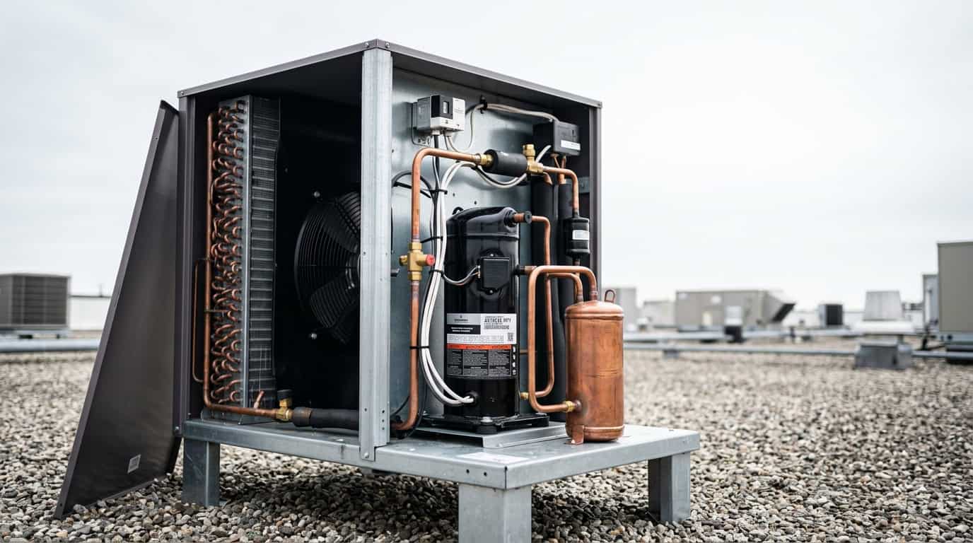
Quick answer: The four primary parts of a vapor-compression refrigeration system are the compressor, condenser, expansion device, and evaporator. A working commercial or industrial system also needs flow-control valves, a receiver, filter drier, accumulator, oil-management parts, fans or pumps, sensors, electrical controls, safety devices, piping, insulation, drainage, and service connections. This guide names 112 parts and explains what each one does.
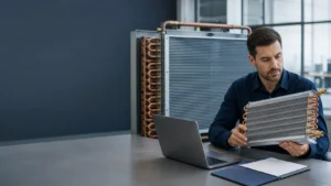
The phrase parts of a refrigeration system can describe a single component, a coil assembly, a condensing unit, or a complete machine. That difference matters when a buyer requests a replacement or an OEM quotation. A condenser coil is not the same product as a condensing unit. An evaporator core is not a complete cold-room unit cooler. A compressor is one part of the circuit, not the refrigeration system by itself.
This reference is organized for engineers, procurement teams, distributors, service companies, and equipment manufacturers. It starts with the four primary components, then maps 112 commonly used names across six component families. The final sections explain the refrigeration cycle, application differences, RFQ data, identification mistakes, maintenance clues, and the information a supplier needs before confirming a design.
Parts of a refrigeration system at a glance
The table below gives the shortest useful map. The exact configuration changes with refrigerant, capacity, temperature range, cabinet layout, ambient conditions, safety requirements, and whether the system is residential, commercial, industrial, transport, or process equipment.
| Component family | Typical examples | Primary role | Buyer question |
|---|---|---|---|
| Compression | Reciprocating, scroll, screw, centrifugal | Raises refrigerant pressure and moves the circuit mass flow | What capacity, refrigerant, speed range, oil system, and motor supply are required? |
| Heat rejection | Air-cooled condenser, water-cooled condenser, gas cooler | Rejects heat from the refrigerant to air, water, or another sink | What ambient, water temperature, airflow, fouling, and corrosion conditions apply? |
| Expansion and metering | TXV, EEV, capillary tube, fixed orifice | Reduces pressure and controls the refrigerant entering the evaporator | What load range, superheat target, refrigerant, and pressure drop must be controlled? |
| Heat absorption | DX evaporator, flooded evaporator, finned coil, plate evaporator | Absorbs heat from air, water, glycol, product, or a process stream | What entering condition, outlet condition, frost risk, drainage, and face area are needed? |
| Liquid and oil management | Receiver, accumulator, oil separator, filter drier, sight glass | Stores, separates, filters, dries, and returns fluids to protect the circuit | What charge volume, oil return path, moisture risk, and service access are expected? |
| Controls and protection | Pressure switches, sensors, controller, relief valve, leak detector | Measures conditions, changes operating state, and limits unsafe operation | Which control points, alarms, setpoints, interlocks, and documents must be supplied? |
The Danfoss cold-room reference is useful for seeing how compressors, condensers, evaporators, valves, controls, and enclosure hardware are combined in a real refrigeration installation. The University of Michigan refrigeration reference also provides a clear engineering explanation of the basic cycle and compressor families.
The four primary components of a refrigeration system
1. Compressor
The compressor draws low-pressure vapor from the evaporator and raises it to a higher pressure and temperature. It provides the pressure difference that drives refrigerant through the circuit. Depending on the equipment, the compressor may be reciprocating, scroll, screw, centrifugal, rotary, hermetic, semi-hermetic, open-drive, fixed-speed, or variable-speed.
For a replacement or OEM build, a compressor cannot be selected from horsepower alone. The supplier needs the refrigerant, required capacity, evaporating and condensing conditions, suction and discharge pressures, speed range, motor supply, oil type, starting method, sound limit, mounting, and control strategy. A compressor that fits the cabinet can still be wrong if its operating envelope or oil return conditions do not match the system.
Common compressor clues include high discharge temperature, short cycling, abnormal vibration, oil loss, repeated overload trips, low suction pressure, and capacity loss. These symptoms can also come from airflow, charge, metering, or control problems, so the complete system should be checked before the compressor is condemned.
2. Condenser or gas cooler
The condenser rejects heat from the high-pressure refrigerant. In a conventional cycle, the refrigerant desuperheats, condenses, and may be subcooled as it passes through the condenser. Air-cooled designs use fans and finned tubes. Water-cooled designs use a shell-and-tube, coaxial, or plate construction. Evaporative condensers use water evaporation to improve heat rejection.
When a refrigerant operates above its critical point, the heat-rejection component is more accurately called a gas cooler because the fluid does not condense in the same way. The correct terminology affects the pressure rating, control method, design conditions, and safety review.
A condenser quotation should state the heat-rejection duty, refrigerant, entering air or water temperature, design ambient, airflow or water flow, allowable pressure drop, connection sizes, material, fin spacing, coating, fan selection, and service clearance. High condensing pressure can be caused by a dirty coil, blocked airflow, failed fan, excessive ambient temperature, non-condensable gas, or an undersized heat-rejection surface.
3. Expansion or metering device
The expansion device creates the pressure drop between the high side and low side. It also meters refrigerant into the evaporator so the evaporator can absorb heat without allowing excessive liquid to reach the compressor. A thermostatic expansion valve uses superheat feedback. An electronic expansion valve uses a controller and sensor signals. A capillary tube or fixed orifice provides a simpler fixed restriction.
The correct metering device depends on refrigerant, capacity range, evaporating temperature, condenser pressure, load variation, system charge, pressure drop, and control response. A valve selected only by connection size may be unstable or may starve the evaporator. A fixed restriction that works at one ambient condition may not control a system with a wide load or ambient range.
4. Evaporator
The evaporator absorbs heat from cabinet air, room air, water, glycol, product, or a process stream. Refrigerant usually enters as a low-pressure mixture and leaves as vapor. The design must account for heat duty, temperature difference, airflow, moisture, frost, defrost, drainage, circuiting, face velocity, material, and available installation envelope.
An evaporator coil is often described by its role, while the physical construction may be finned-tube, microchannel, plate, shell-and-tube, roll-bond, wire-on-tube, or another design. For a replacement, the original appearance is not enough. Tube circuiting, internal volume, connection position, fin spacing, drain direction, mounting, refrigerant, and pressure rating all matter.
The 112 parts of a refrigeration system
The entries below are a practical vocabulary list for drawings, catalogs, service reports, and RFQs. Several names describe a construction, a component role, or a subassembly rather than a complete machine. The definitions are intentionally concise so the list can be used as a technical reference.
Group A: Compressors and prime movers
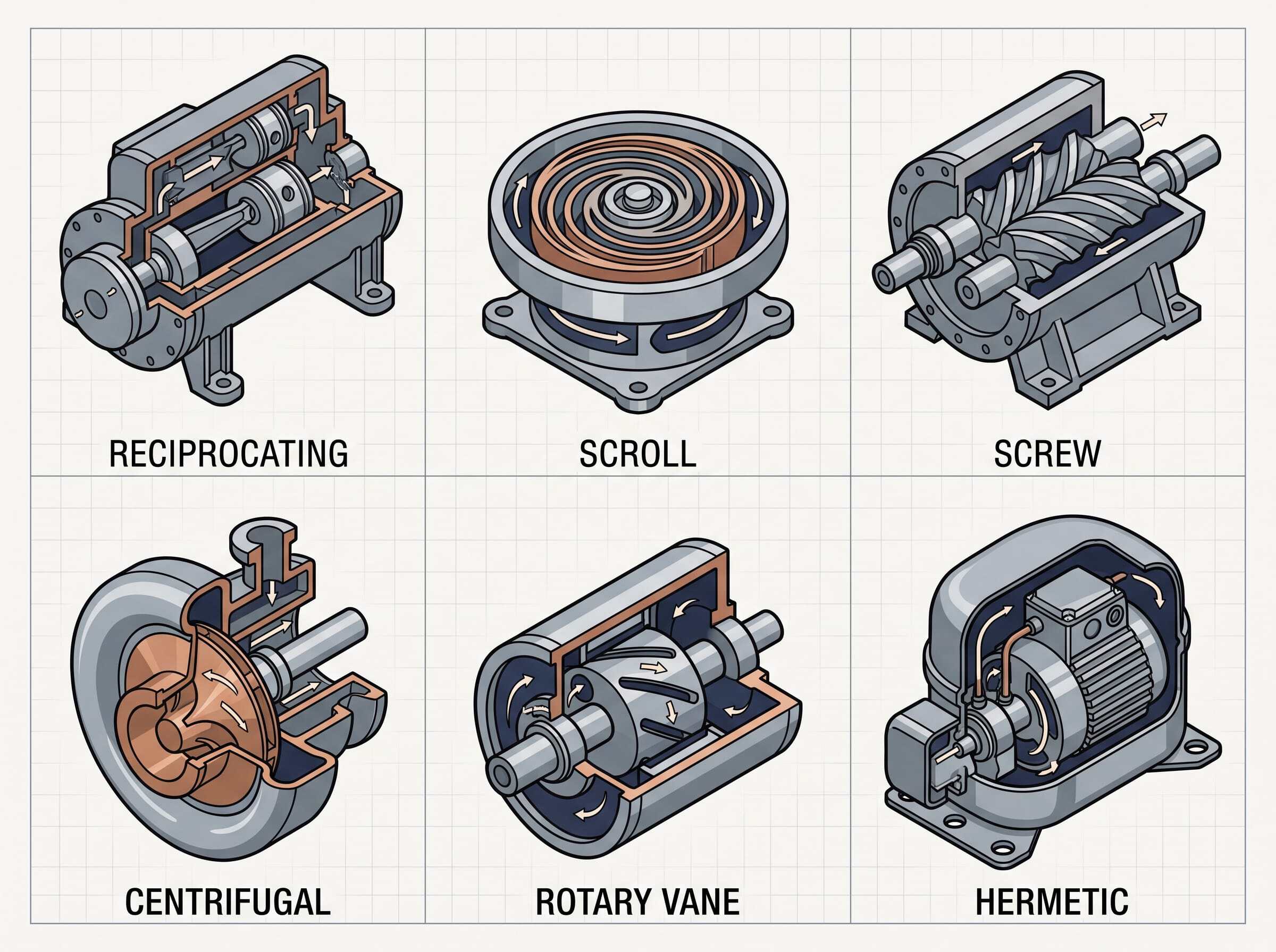
- Reciprocating compressor. A piston compresses vapor inside a cylinder. It is common in small and medium systems and can be configured for multiple cylinders, stages, or capacity-control methods.
- Scroll compressor. Two interleaved scrolls compress vapor in progressively smaller pockets. Scrolls are widely used in compact commercial, comfort-cooling, and heat-pump equipment.
- Screw compressor. Rotating male and female rotors compress vapor continuously. Screw compressors suit larger capacities and often include slide-valve or variable-speed capacity control.
- Centrifugal compressor. An impeller raises vapor pressure through velocity and diffusion. It is normally applied to large chillers and systems with a stable high-volume operating range.
- Rotary vane compressor. Sliding vanes divide a rotating chamber into changing volumes. The design is compact, but oil management and wear conditions must be reviewed.
- Rotary piston compressor. An eccentric or rolling piston compresses vapor in a rotary cylinder. This construction appears in compact refrigeration and appliance equipment.
- Hermetic compressor. The motor and compressor are sealed inside one welded shell. It reduces shaft-seal leakage paths, but field repair is generally more limited than with an open-drive design.
- Semi-hermetic compressor. The motor and compressor share a bolted serviceable housing. The construction supports inspection and repair in many commercial systems.
- Open-drive compressor. A motor outside the compressor drives the shaft through a coupling or belt. Shaft seals, alignment, guarding, and maintenance access need specific attention.
- Single-stage compressor. Vapor pressure is raised in one compression step. It is suitable when the pressure ratio and discharge temperature remain within the approved operating envelope.
- Two-stage compressor. Compression is divided between two stages to support a higher pressure ratio or lower evaporating temperature. Intercooling and oil return become important design inputs.
- Compound compressor. Two or more compression paths operate in a coordinated circuit. It can improve low-temperature performance and capacity flexibility.
- Inverter compressor. An inverter-driven motor changes speed through an electronic drive. It can match capacity more closely to load, but the motor, drive, wiring, and control compatibility must be specified together.
- Variable-speed compressor. Compressor speed changes within a defined range to control capacity. The system needs an approved speed envelope, oil-return strategy, and startup method.
- Compressor motor. The motor supplies the mechanical power for compression. Voltage, frequency, phase, efficiency, starting current, insulation, and thermal protection must match the equipment.
- Crankcase heater. An electric heater limits refrigerant migration and oil dilution during shutdown. Its position, wattage, control logic, and safety protection should be confirmed.
- Oil pump. The pump circulates lubricant through compressor bearings, crank mechanisms, or an external oil circuit. Differential pressure is often monitored to protect the compressor.
- Oil sump. The sump collects lubricant inside or below the compressor housing. The oil level and return rate must remain stable across operating and shutdown conditions.
- Discharge muffler. A muffler reduces discharge pulsation and transmitted sound. It may also reduce vibration in the discharge line and connected heat exchanger.
- Vibration isolator. Rubber, spring, or engineered mounts limit vibration transfer from the compressor to the frame and refrigerant piping.
Group B: Condensers, evaporators, coils, and heat-transfer parts
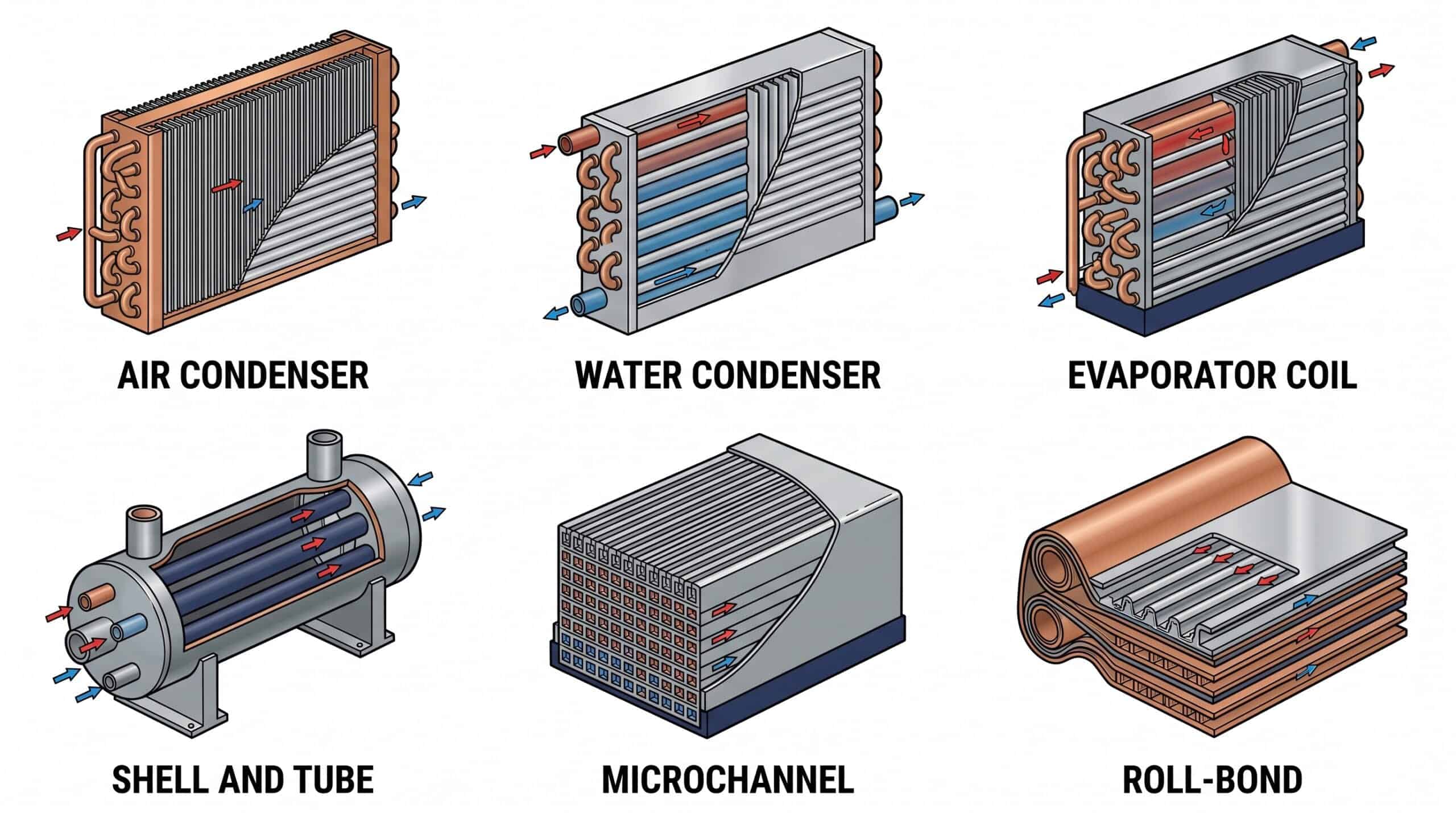
- Air-cooled condenser. A finned coil and fan reject refrigerant heat to outdoor or room air. Ambient temperature, airflow, fin spacing, and corrosion exposure control its practical capacity.
- Water-cooled condenser. Water removes heat from the refrigerant through tubes, plates, or a coaxial passage. Water quality, flow, approach temperature, and cleaning access need review.
- Evaporative condenser. A water spray and airflow improve heat rejection through evaporation. Water treatment, drift control, freezing protection, and maintenance are part of the design.
- Shell-and-tube condenser. Refrigerant and cooling water occupy separate shell or tube passages. The design supports robust pressure containment and service options for many industrial systems.
- Coaxial condenser. One tube is arranged inside another so two fluids exchange heat across the inner wall. It is compact and useful for water-source equipment and small heat pumps.
- Brazed plate condenser. Stamped plates create alternating channels that are brazed into a compact heat exchanger. Fluid cleanliness, pressure rating, and repair strategy should be agreed before use.
- Gas cooler. A high-pressure gas-side heat exchanger rejects heat without relying on conventional condensation. Its design pressure and control strategy are specific to the refrigerant and cycle.
- Receiver condenser. A condenser assembly is paired with liquid storage or an integrated receiver section. The supplier should state usable volume and operating conditions separately.
- Direct-expansion evaporator. Refrigerant expands and evaporates directly inside the coil. It is common in air coolers, display cases, air handlers, and packaged refrigeration equipment.
- Flooded evaporator. The evaporator maintains a liquid-rich refrigerant condition on the boiling side. Level control, oil return, separator design, and compressor protection are essential.
- Dry-expansion evaporator. Refrigerant is metered so the outlet becomes vapor before leaving the coil. Superheat control protects the compressor from liquid carryover.
- Forced-air evaporator. A fan moves air across an evaporator coil. Fan selection, face velocity, frost, condensate, and defrost determine the installed result.
- Plate evaporator. Refrigerant and a secondary fluid or product stream pass through formed plate channels. Plate thickness, gasket or brazed construction, and sanitation requirements can change the selection.
- Shell-and-tube evaporator. Refrigerant boils on one side of a tube bundle while water, glycol, or process fluid flows on the other. It suits larger liquid-cooling duties and serviceable installations.
- Flooded chiller. A chiller uses a flooded evaporator to cool water or another secondary fluid. The vessel, separator, oil return, and level controls must be treated as one system.
- Finned-tube coil. Tubes and external fins create an extended airside surface. Tube material, fin material, fin pitch, circuiting, and coating define much of the coil behavior.
- Microchannel coil. Flat multiport tubes and louvered fins create compact refrigerant passages. Distribution, corrosion protection, brazing quality, and repair options deserve early review.
- Wire-on-tube condenser. Wire is attached to a refrigerant tube to add surface and provide a simple structural grid. It appears in appliance condensers and compact equipment.
- Tube-on-plate condenser. A tube is bonded or formed against a plate that spreads heat and provides mounting. The thermal joint and plate flatness are important to performance.
- Roll-bond evaporator. Internal channels are formed between bonded aluminum sheets. Roll-bond panels are common in appliances and require careful review of pressure, shape, ports, and forming.
Group C: Expansion, distribution, and refrigerant-flow controls
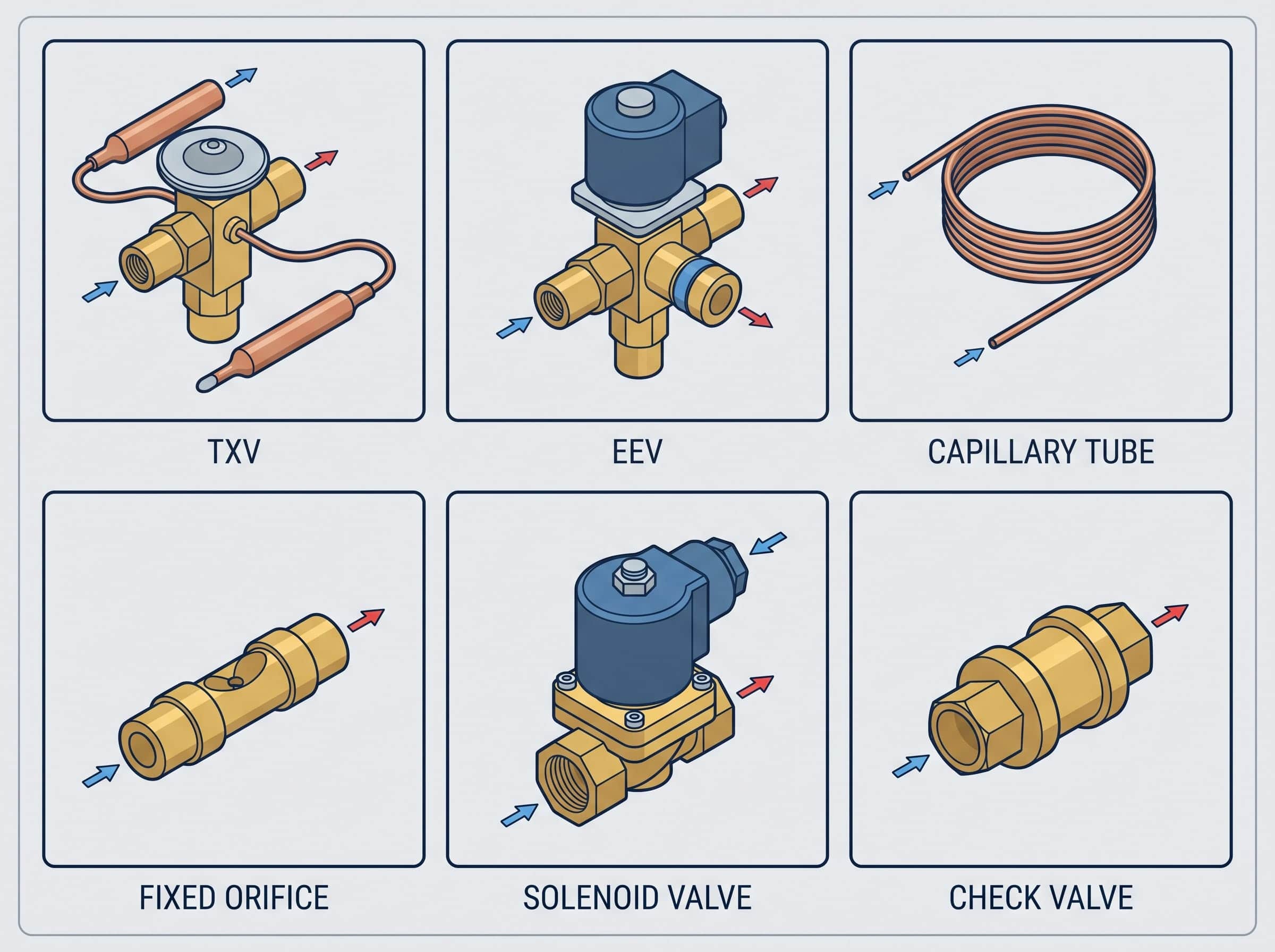
- Thermostatic expansion valve. A TXV meters liquid refrigerant using a sensing bulb, pressure element, and superheat response. Bulb mounting and equalizer arrangement affect control stability.
- Electronic expansion valve. An EEV uses an actuator and controller to regulate the opening electronically. It can respond to changing loads, but sensors and control parameters must be matched.
- Capillary tube. A long small-bore tube creates a fixed pressure drop. Length, internal diameter, refrigerant, charge, and operating conditions must be considered together.
- Fixed orifice. A calibrated opening meters refrigerant with no active feedback. It is simple, but it has less ability to handle a wide load range.
- Float valve. A float position responds to liquid level and opens or closes refrigerant flow. The vessel geometry and pressure conditions must be compatible with the valve.
- Hand expansion valve. A manually adjusted valve restricts flow during commissioning or special process operation. It is not normally a substitute for automatic load control.
- Pressure-regulating valve. A pressure-regulating valve maintains a target pressure in a suction, discharge, receiver, or bypass branch. Setpoint, flow range, and pressure rating should be stated.
- Solenoid valve. An electrically actuated valve starts or stops refrigerant flow. Coil voltage, normally open or closed state, differential pressure, and refrigerant compatibility are essential.
- Check valve. A check valve prevents reverse flow. Cracking pressure, orientation, leakage limit, and installation position can affect system behavior.
- Three-way valve. A three-way valve diverts or mixes flow between branches. The port arrangement and actuator sequence must be clear on the drawing.
- Four-way reversing valve. A reversing valve changes the flow path for heating and cooling operation. Port mapping, pilot control, coil voltage, and pressure balance require verification.
- Hot-gas bypass valve. This valve routes discharge gas toward the low side to prevent excessively low suction pressure or support capacity control in selected conditions.
- Suction stop valve. A service or isolation valve closes the suction path for pump-down, repair, or component replacement. Access and locking requirements should be included.
- Liquid-line valve. This valve isolates or controls the liquid path between the receiver, filter drier, metering device, and evaporator.
- Distributor. A distributor divides liquid and vapor flow among several evaporator circuits. Equal circuit loading depends on geometry, pressure drop, and installation orientation.
- Distributor nozzle. The nozzle creates the velocity and pressure pattern needed to feed a distributor. Its bore and position are part of the coil circuit design.
- Orifice. A calibrated opening limits or directs flow in a branch. Orifice size, material, and upstream filtration should be recorded for service replacement.
- Injection valve. An injection valve adds refrigerant or liquid cooling to a compressor, heat exchanger, or selected circuit branch under controlled conditions.
- Receiver outlet valve. The outlet valve controls or isolates liquid leaving the receiver. It must be rated for the receiver pressure and the refrigerant used.
- Service valve. A service valve provides isolation, charging, recovery, or pressure measurement access. Port location and cap protection matter during maintenance.
Group D: Liquid, oil, moisture, and pressure-management parts
- Liquid receiver. A receiver stores liquid refrigerant and helps accommodate charge variation. Usable volume, relief protection, orientation, and maximum fill condition must be checked.
- Suction accumulator. An accumulator separates unwanted liquid from suction vapor before the compressor. The design must support return of oil and controlled liquid handling.
- Oil separator. An oil separator removes lubricant from discharge gas and returns it to the compressor or oil circuit. Separation efficiency and return control affect compressor life.
- Oil reservoir. A reservoir stores lubricant for an external oil-management system. Level control and oil return must remain stable across load and compressor staging.
- Filter drier. A filter drier removes moisture, acid, and particulate contamination from the liquid line. Capacity, pressure drop, shell material, and replaceability should match the refrigerant and charge.
- Suction filter. A suction filter captures debris before it reaches the compressor. It is often used after a motor burn or major component failure and should not create excessive suction pressure drop.
- Sight glass. A sight glass gives a visual indication of liquid condition or moisture status. Bubbles alone do not prove undercharge because operating conditions and pressure drop also matter.
- Moisture indicator. An indicator changes color or provides a signal when moisture conditions exceed its reference range. It is one input to service decisions, not a replacement for recovery and testing procedures.
- Liquid-line strainer. A strainer catches larger particles before they reach valves or metering devices. Mesh size and service access should suit the expected contamination risk.
- Oil filter. An oil filter removes particles from lubricant. The filter rating, bypass behavior, oil compatibility, and replacement interval should be defined.
- Oil differential switch. A differential switch monitors the pressure available to the oil circuit. It can stop the compressor when lubrication pressure is insufficient.
- Crankcase pressure regulator. A CPR limits suction pressure entering the compressor during startup or high-load pull-down. It protects the motor from excessive current and load.
- Suction accumulator heater. A heater reduces liquid migration or freezing risk in a selected accumulator application. The control logic and surface temperature must be reviewed.
- Pressure equalizer. An equalizer connects a sensing or vessel space so a valve or float responds to the intended pressure. Incorrect routing can make a control appear to fail.
- Flash tank. A flash tank separates vapor and liquid after a pressure reduction or in an economized cycle. Level control, vapor routing, and pressure rating are key design inputs.
- Economizer. An economizer improves selected compressor or cycle conditions by using an intermediate pressure branch, subcooling path, or vapor injection arrangement.
- Intercooler. An intercooler reduces gas temperature between compression stages or between a compression branch and the main discharge path.
- Oil-return line. The oil-return line carries separated lubricant back to the compressor or oil reservoir. Slope, velocity, pressure balance, and oil viscosity affect reliability.
- Liquid-injection line. This line carries controlled liquid refrigerant to cool a compressor, discharge path, or selected heat exchanger branch.
- Discharge pressure regulator. A discharge-side regulator maintains a defined pressure or protects a downstream branch during changing ambient or load conditions.
Group E: Air, water, mounting, and drainage parts
- Axial fan. An axial fan moves air parallel to its shaft. It is common for condenser and evaporator sections where a large air volume and moderate pressure rise are required.
- Centrifugal fan. A centrifugal fan changes airflow direction through an impeller and can provide higher static pressure for ducts, filters, and compact cabinets.
- EC fan motor. An electronically commutated motor combines efficient motor control with variable-speed operation. Signal type, speed range, and fault output must be specified.
- Fan guard. A guard protects people and equipment from rotating fan parts. Its opening size, material, corrosion protection, and clearance should be checked.
- Fan blade. The blade geometry determines airflow, sound, power, and operating range. Diameter, pitch, rotation, balance, and motor pairing matter.
- Fan shroud. A shroud directs air through the fan and reduces bypass. The gap between blade and shroud strongly affects performance.
- Air baffle. A baffle guides air through a coil or separates inlet and outlet streams. Poor baffle placement can create recirculation and uneven coil loading.
- Drain pan. A pan collects condensate from an evaporator or cabinet. Slope, material, outlet position, insulation, and cleanability prevent standing water.
- Drain heater. A heater protects a condensate drain from freezing during low-temperature operation or defrost. Wattage, control, and electrical protection must be confirmed.
- Condensate pump. A pump removes water when gravity drainage is unavailable. Lift height, flow rate, alarm contact, and cleaning access are important.
- Water pump. A pump circulates water, glycol, or process fluid through a heat exchanger loop. Flow, head, temperature, material, and seal compatibility must match.
- Flow switch. A flow switch confirms that water or glycol is moving before the compressor or heater is enabled. Setpoint and installation direction should be documented.
Group F: Tubing, controls, electrical, safety, and service parts
- Glycol loop. A glycol loop transfers cooling between the refrigeration machine and remote loads. Concentration, freeze point, viscosity, pump head, and compatible materials must be recorded.
- Copper tube. Copper tube carries refrigerant or secondary fluid through coils and piping. Tube size, wall thickness, temper, cleanliness, joining method, and pressure rating are specification items.
- Aluminum tube. Aluminum tube reduces weight and can support compact heat exchangers. Joining, corrosion exposure, brazing method, and pressure validation require careful review.
- Casing. A casing surrounds and protects a coil, fan, vessel, or control assembly. It also controls airflow, mounting, drainage, and service access.
- Support bracket. A bracket carries a component and transfers its loads into the frame or cabinet. Hole pattern, vibration, corrosion, and assembly clearance should be shown on the drawing.
- Vibration pad. A pad reduces vibration transfer between a compressor, fan, pump, and equipment frame. Material hardness and compression load affect its performance.
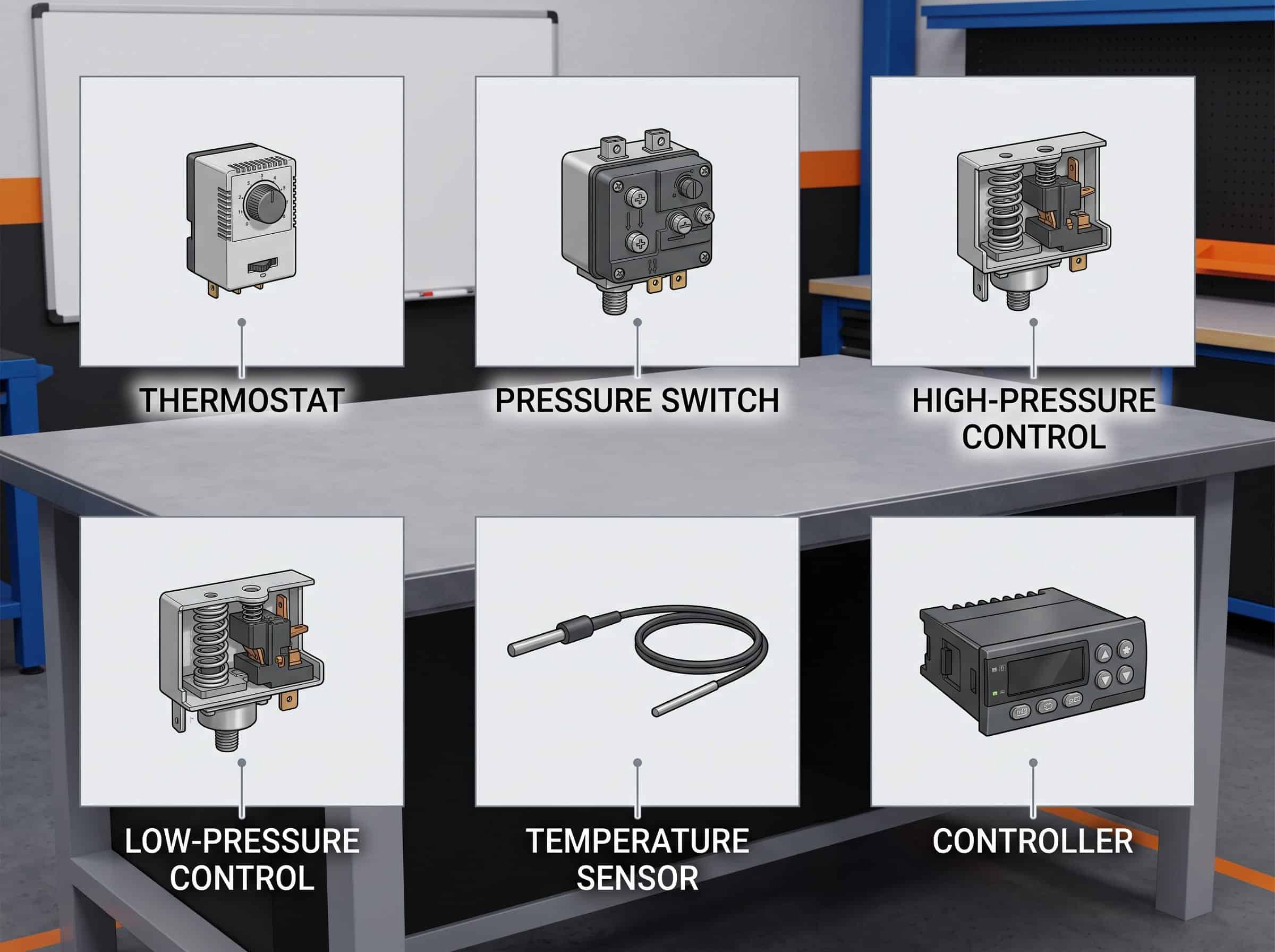
- Thermostat. A thermostat measures or responds to temperature to control cooling, heating, defrost, or a fan. Sensor location and differential setting change the result.
- Pressure switch. A pressure switch changes an electrical state at a defined pressure. Its reset method, cut-in, cut-out, and refrigerant compatibility should be recorded.
- High-pressure control. This control protects the high side from excessive pressure and can also manage condenser fans or floating head pressure.
- Low-pressure control. A low-pressure control protects the compressor, manages pump-down, or starts and stops a system based on suction pressure.
- Temperature sensor. A thermistor, RTD, thermocouple, or digital sensor measures air, fluid, tube, cabinet, or discharge temperature for control and monitoring.
- Pressure transducer. A pressure transducer converts refrigerant pressure into an electrical signal for a controller, display, alarm, or variable-speed drive.
- Refrigeration controller. A controller coordinates compressors, fans, valves, defrost, alarms, and temperature targets. The input list, output list, communication method, and setpoint authority should be defined.
- PLC. A programmable logic controller sequences industrial refrigeration equipment and communicates with a supervisory system. I/O, scan logic, network protocol, and panel documentation are part of the deliverable.
- Defrost controller. A defrost controller starts, stops, and terminates a defrost sequence. Time, temperature, pressure, drain, heater, and fan interlocks need to be coordinated.
- Contactor. A contactor switches a motor, heater, or compressor circuit. Coil voltage, load category, auxiliary contacts, and short-circuit protection should be matched.
- Overload protector. An overload device limits motor damage from excessive current or temperature. It is not a substitute for correct sizing, airflow, charge, or phase protection.
- Refrigerant leak detector. A detector identifies refrigerant concentration or leakage in equipment or occupied space. Sensor placement, alarm level, calibration, and refrigerant type affect the design.
- Pressure relief valve. A relief valve protects a pressure vessel or isolated liquid section from overpressure. Discharge routing, set pressure, capacity, and local requirements must be reviewed by a qualified engineer.
- Service port. A service port provides access for pressure measurement, evacuation, charging, recovery, or diagnostic testing. Cap sealing and location affect long-term leak risk.
How the parts work together in the refrigeration cycle
The refrigeration cycle is easier to understand when the components are grouped by pressure and heat direction:
- Low-pressure vapor leaves the evaporator. The evaporator has absorbed heat from cabinet air, room air, water, glycol, product, or a process stream.
- The compressor raises pressure. The compressor moves vapor into the high side and adds the work needed to drive the circuit.
- The condenser or gas cooler rejects heat. Fans, water, or evaporation remove the absorbed load plus compressor work. A receiver may store liquid after the heat-rejection section.
- The expansion device reduces pressure. A TXV, EEV, capillary tube, or fixed orifice meters the refrigerant into the evaporator. The pressure drop creates the low-temperature condition needed for heat absorption.
- Controls close the feedback loop. Pressure, temperature, level, airflow, water flow, and frost signals influence valves, fans, compressor speed, defrost, and alarms.
- Oil-management parts protect the compressor. Oil separators, reservoirs, filters, return lines, and accumulators keep lubricant moving without allowing damaging liquid to enter the compressor.
The high side normally includes the compressor discharge, condenser or gas cooler, receiver, liquid line, filter drier, and the inlet of the expansion device. The low side normally includes the expansion outlet, evaporator, suction line, accumulator when used, and compressor inlet. Exact boundaries differ by system design.
The refrigerant cycle guide explains the four stages in more detail, while the heat exchanger types reference explains why the condenser and evaporator can use different constructions even though both transfer heat.
Parts by refrigeration application
The four primary functions remain recognizable across applications, but the supporting components change substantially. A domestic refrigerator, a walk-in cold room, an industrial ammonia system, and a transport unit should not be quoted from the same generic parts list.
| Application | Common component emphasis | Important selection details |
|---|---|---|
| Residential refrigerator | Compact compressor, roll-bond or wire-on-tube exchanger, capillary tube, thermostat, fan, drain system | Cabinet envelope, sound, low charge, startup behavior, forming, insulation, and appliance testing |
| Commercial display case | DX evaporator, TXV or EEV, condenser, fans, controller, defrost parts, drain pan | Product temperature, door opening, humidity, frost, lighting heat, airflow, service access, and food-safe cleaning |
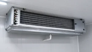
| Walk-in cold room | Remote condensing unit, unit cooler, receiver, filter drier, solenoid, controller, defrost heater | Room volume, product load, door traffic, ambient, defrost method, drain heat, refrigerant piping, and installation clearance |
| Blast chiller or freezer | High-capacity compressor, forced-air evaporator, large condenser, expansion control, sensors, defrost, and fan system | Pull-down duty, air velocity, product loading, low evaporating temperature, peak current, and repeatability |
| Industrial refrigeration | Screw or reciprocating compressor, vessels, pumps, oil system, valves, PLC, relief protection, and remote heat exchangers | Refrigerant classification, pressure vessels, redundancy, maintenance access, safety interlocks, and documented operating limits |
| Transport refrigeration | Compact compressor, condenser, evaporator, controller, battery or engine drive, sensors, and vibration-resistant mounts | Shock, vibration, power source, ambient range, defrost, weight, service network, and connection durability |
| Heat pump | Reversible compressor, four-way valve, outdoor coil, indoor coil, expansion devices, sensors, and defrost controls | Heating and cooling capacity, reversing sequence, low ambient operation, frost, noise, pressure balance, and controls |
| Process cooling | Shell-and-tube or plate exchanger, pump, secondary loop, controller, flow switch, sensors, and filtration | Fluid chemistry, solids, viscosity, sanitation, temperature stability, flow, pressure drop, cleaning, and materials |
Component, subassembly, and complete unit are different terms
These terms are often mixed in product searches and purchase orders:
- A component is one functional part, such as a compressor, valve, fan motor, filter drier, sensor, or copper tube.
- A coil or heat-exchanger core is an assembly of tubes, fins, headers, plates, ports, and sometimes a frame. It may still need a fan, drain pan, casing, control, and piping before it can operate.
- A condenser or evaporator assembly normally includes the heat-transfer surface and some combination of casing, headers, connections, drain, fan, or controls. The exact scope must be stated.
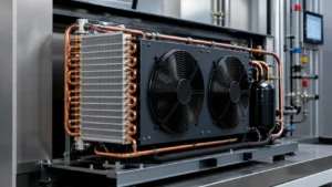
- A condensing unit usually combines a compressor, condenser, fan, receiver or controls, frame, and associated piping. It is not the same as a condenser coil.
- A refrigeration system combines the high side, low side, metering, controls, protection, piping, and service provisions into a working circuit.
- A complete cabinet or machine adds the enclosure, insulation, doors, product space, electrical panel, software, drainage, installation provisions, and acceptance tests.
This distinction prevents a common RFQ error: asking for a “complete refrigeration unit” when the actual need is a replacement evaporator coil, or requesting a “condenser” when the project requires a complete condensing unit with compressor and controls.
What an OEM buyer should specify before requesting a quote
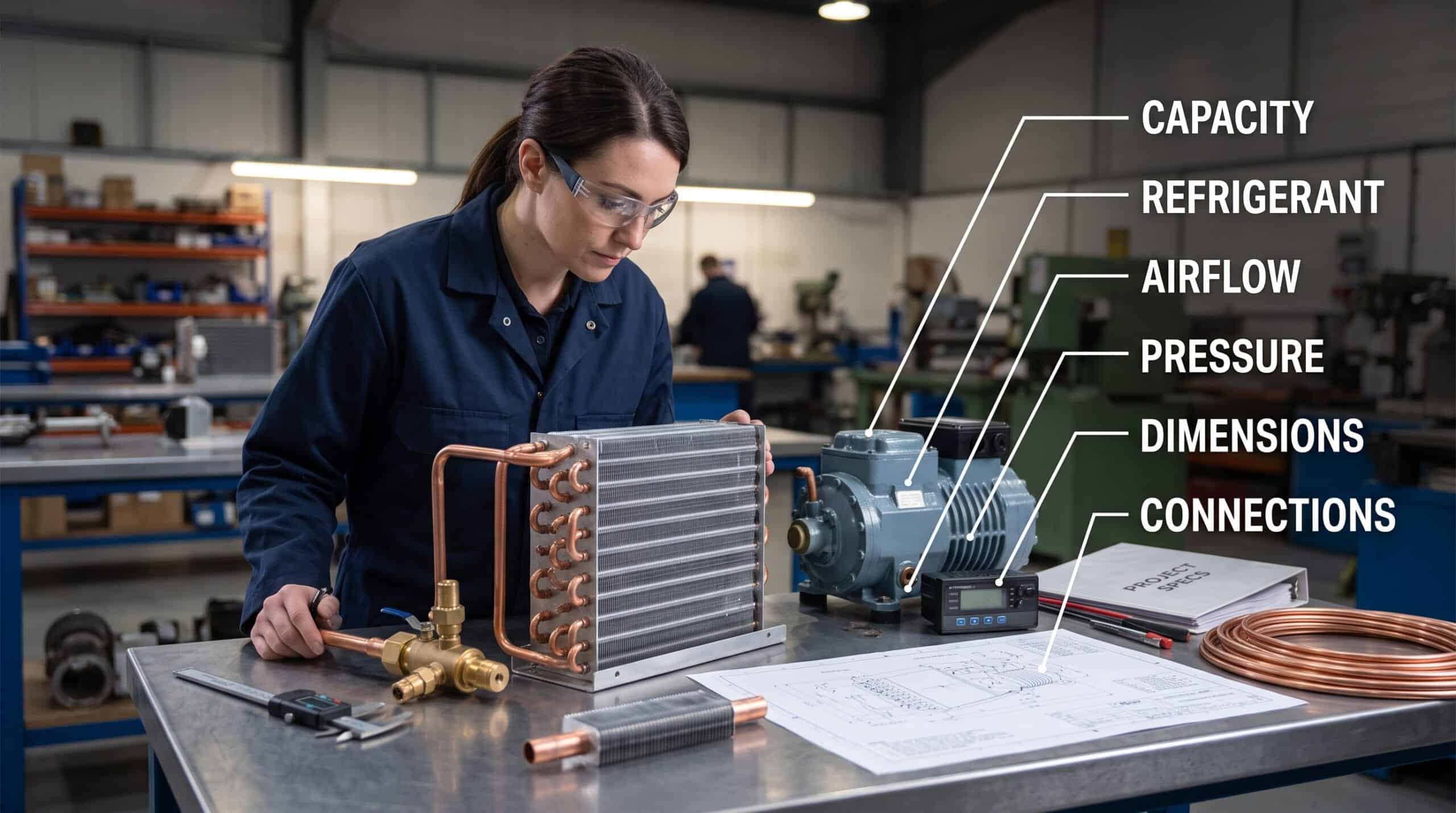
An accurate parts list is only the first step. A manufacturer needs operating and installation data to decide whether an existing part can be replaced or a new assembly must be designed.
Application and duty
State what the equipment does and where the part is installed. Examples include a beverage cooler, walk-in freezer, ice machine, refrigerated display case, blast chiller, heat pump, process chiller, or transport container. Add required capacity in watts, kilowatts, BTU/h, tons of refrigeration, or another unambiguous unit.
Refrigerant and operating conditions
Name the refrigerant or secondary fluid. Provide evaporating temperature, condensing or gas-cooler condition, suction and discharge pressure, entering and leaving fluid temperatures, ambient range, and operating modes. If the equipment has several load cases, send the minimum, nominal, and maximum conditions.
Flow and pressure drop
Provide refrigerant mass flow, air volume, water or glycol flow, fan speed, pump flow, and allowable pressure drop where available. A component with more surface is not automatically better if it creates too much fan or pump power demand.
Dimensions, connections, and mounting
Send width, height, depth, tube or plate orientation, connection size, connection position, mounting-hole pattern, drain location, fan clearance, service space, insulation thickness, and any interference zones. A drawing or physical sample is more useful than a product name alone.
Materials, finish, and environment
State tube and fin material, plate material, casing material, coating, joining method, insulation, salt exposure, humidity, dust, washdown, vibration, chemical exposure, and expected service life. Material compatibility can be more important than a small difference in nominal capacity.
Testing and production requirements
Specify leak testing, pressure testing, thermal performance testing, dimensional inspection, material documentation, sample approval, packaging, labeling, MOQ, target lead time, and revision control. The custom refrigerator coil RFQ checklist provides a practical starting format. For a manufacturing discussion, see custom coil fabrication and OEM refrigerator and freezer solutions.
| RFQ field | Example input | Why the field matters |
|---|---|---|
| Part scope | Replacement evaporator coil only, or complete unit cooler | Prevents a mismatch between component, subassembly, and complete unit pricing |
| Refrigerant | Approved refrigerant and oil combination | Sets pressure, material, valve, charge, and compatibility requirements |
| Capacity | Required duty at defined entering and leaving conditions | Prevents selection by physical size or horsepower alone |
| Flow | Airflow, refrigerant mass flow, or water and glycol flow | Controls heat transfer, pressure drop, fan power, and pump power |
| Envelope | Face size, depth, connections, drain, and mounting | Confirms that the part can fit, connect, and be serviced |
| Environment | Humid freezer, coastal outdoor unit, or washdown area | Guides fin pitch, coating, material, drainage, and corrosion review |
| Acceptance | Drawing approval, leak test, pressure test, and sample inspection | Creates a clear release gate before repeat production |
Common mistakes when identifying refrigeration components
Matching by appearance only
Two coils can have the same face dimensions but different tube circuits, internal volumes, fin pitches, connection positions, or refrigerant duties. Measure and document the physical part, but also recover the operating data and drawing information.
Confusing a condenser with a condensing unit
A condenser rejects heat. A condensing unit normally combines a compressor, condenser, fan, frame, controls, and piping. The quotation scope should name the included parts.
Ignoring the refrigerant change
A component designed for one refrigerant may not have the required pressure rating, valve behavior, lubricant compatibility, or charge control for another. Refrigerant information belongs at the top of the RFQ, not in a later service note.
Omitting airflow or water flow
Heat exchangers are selected for a fluid condition and a flow path. A condenser coil without airflow data or a water exchanger without flow and water-quality data cannot be compared reliably.
Treating a replacement coil as universal
An evaporator replacement also has to drain, defrost, mount, connect, and fit within the cabinet. A condenser replacement has to reject the duty at the real ambient and fan condition.
Forgetting service access and drainage
Filters, valves, sensors, drain pans, and coils need access for inspection and cleaning. A part that performs in a test drawing but cannot be removed or drained in the machine will create a maintenance problem.
Assuming a pressure symptom identifies one failed part
Low suction pressure may result from low charge, a restricted filter drier, a starved expansion device, low airflow, frost, or a control setting. High discharge pressure may come from fouling, fan failure, high ambient, non-condensable gas, or incorrect charge. Gather evidence before ordering a replacement.
Maintenance and failure clues by component family
The table is a diagnostic orientation aid, not a substitute for qualified refrigeration service. Electrical, pressure, refrigerant recovery, and combustion-related work should follow applicable safety procedures and local requirements. The EPA retail refrigeration resource is a useful terminology and compliance starting point for commercial equipment in the United States.
| Observed symptom | Component families to inspect | Evidence to collect | When to request a review |
|---|---|---|---|
| High condensing pressure | Condenser, fan, airflow, charge, pressure control | Ambient, entering and leaving air, fan rotation, coil cleanliness, pressure trend | When pressure remains high after airflow and obvious fouling checks |
| Low suction pressure | Evaporator, expansion device, filter drier, charge, airflow | Superheat, frost pattern, air temperature, filter pressure drop, operating mode | When the restriction or load condition cannot be confirmed safely |
| Liquid reaching compressor | Expansion device, accumulator, evaporator circuit, controls | Superheat, suction temperature, load change, valve response, accumulator condition | Immediately when liquid return or compressor damage is suspected |
| Repeated motor overload | Compressor, electrical supply, condenser, controls | Voltage, current, phase balance, pressure ratio, discharge temperature, start sequence | Before replacing the compressor without proving the operating cause |
| Frost closes evaporator face | Evaporator, defrost controller, drain, fan, door or airflow | Defrost sequence, termination sensor, drain condition, fan operation, door opening | When frost returns after the defrost and airflow cause is corrected |
| Water inside cabinet | Drain pan, drain heater, drain line, condensate pump, insulation | Pan slope, outlet blockage, heater state, pump alarm, cabinet temperature | When water can reach electrical parts or product |
| Unstable temperature | Controller, sensors, metering valve, fan, compressor speed | Sensor location, setpoints, response trend, valve position, fan and compressor command | When the control loop cannot hold the specified product or process condition |
| Oil level falls | Oil separator, return line, accumulator, compressor, piping | Oil level, separator return, line slope, velocity, refrigerant migration, operating range | When oil is not returning or compressor lubrication is uncertain |
Current component design and procurement considerations for 2026
Refrigeration design is moving toward tighter package envelopes, lower internal refrigerant volume, variable-speed operation, sensor-rich control, corrosion protection, and easier documentation. These are design directions, not universal reasons to replace one component family with another.
Microchannel and compact plate constructions can reduce size and internal volume, but they may require more careful distribution, cleaning, repair, and corrosion review. Finned-tube coils remain useful when a buyer needs adaptable geometry, service familiarity, a selected fin pitch, or a specific cabinet layout. The best choice depends on the operating envelope and acceptance test.
Variable-speed compressors and EC fans can improve part-load control, but the control system must define minimum speed, oil return, startup, fault handling, sensor placement, and communication. A motor or fan should not be upgraded in isolation from the controller and electrical protection.
Alternative refrigerants and system pressure classes also make documentation more important. The ASHRAE handbook chapter on refrigeration is a useful technical reference for terminology and design context. For fluid property work, the NIST Chemistry WebBook fluid database can support preliminary calculations, while final design values should come from the approved project data and equipment specification.
Compact parts do not remove the need for service planning. A smaller coil may have less room for cleaning. A smaller passage may be less tolerant of debris. A sensor-rich system still needs documented setpoints, alarms, calibration, and manual override rules. Buyers should ask for the drawing, test conditions, material details, connection schedule, and maintenance access before approving a component family.
Frequently asked questions about refrigeration system components
What are the four main parts of a refrigeration system?
The four primary parts are the compressor, condenser, expansion or metering device, and evaporator. A practical installation also includes piping, refrigerant charge, controls, safety devices, fans or pumps, liquid and oil management, drainage, electrical protection, and service access.
What is the difference between a condenser and a condensing unit?
A condenser is the heat-rejection component. A condensing unit is a larger subassembly that commonly includes a compressor, condenser, fan, frame, controls, and associated piping. The exact included parts should be stated in a quotation.
Is an evaporator the same as a heat exchanger?
An evaporator is a heat exchanger designed to absorb heat while refrigerant evaporates. Not every heat exchanger is an evaporator. Condensers, gas coolers, liquid-to-liquid exchangers, and heat-recovery units also transfer heat.
What does a filter drier do in a refrigeration system?
A filter drier captures moisture, acid, and particulate contamination in the liquid line. Its capacity and pressure drop must suit the refrigerant, system charge, expected contamination, and service plan.
Is an expansion valve better than a capillary tube?
Neither is universally better. A TXV or EEV can control a changing load more actively. A capillary tube is simple and cost effective for a defined operating envelope. Select the device using refrigerant, capacity range, pressure conditions, charge, and control requirements.
Which parts are different in a walk-in cold room?
A cold room commonly uses a remote condensing unit, forced-air unit cooler, liquid receiver, filter drier, solenoid or expansion valve, controller, defrost system, drain heater, and refrigerant piping. Room volume, door traffic, humidity, product load, and ambient conditions determine the actual selection.
Can I identify a refrigeration component from a photo?
A photo can help identify a broad family, but it rarely proves capacity, circuiting, internal volume, pressure rating, refrigerant compatibility, or connection details. Add the nameplate, drawing, dimensions, connection locations, operating data, and application.
What information is needed for a replacement refrigeration coil?
Provide the application, refrigerant, capacity, entering and leaving temperatures, airflow or fluid flow, design pressure, face dimensions, depth, tube and fin material, circuiting if available, connections, drain, mounting, coating, environment, and required tests.
What protects the compressor from liquid refrigerant?
Depending on the system, protection can include a correctly selected expansion device, suction accumulator, superheat control, crankcase heater, pump-down logic, liquid injection control, and appropriate operating procedures. The complete circuit must be reviewed because one part cannot compensate for every control error.
How should an OEM request a refrigeration component quotation?
Send the application, part scope, refrigerant or secondary fluid, capacity, temperatures, pressures, flow rates, dimensions, connections, materials, environment, testing, packaging, MOQ, and target schedule. Include a drawing, sample, or clear installation photos when available.
From a component list to a buildable specification
A names list is valuable when it helps a buyer describe the part accurately. The next step is to connect the name to its duty, fluid, pressure, dimensions, mounting, control method, service plan, and acceptance test. That information lets a manufacturer decide whether a standard part, modified assembly, or new OEM design is appropriate.
For a coil, condenser, evaporator, heat exchanger, or refrigeration assembly, send the drawing or sample information together with operating conditions. Domi can review the requested scope and identify the component data needed for a manufacturable quotation.
Send Your Refrigeration Component Specification for Review