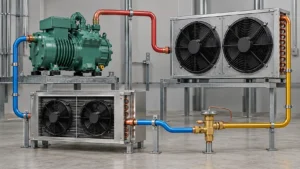
For a low-temperature evaporator, fin spacing is a frost-management decision as much as a heat-transfer decision. Wider spacing can leave room for frost and condensate, while tighter spacing can provide more surface in a compact core but may lose airflow quickly when the inlet face ices. The correct choice depends on storage temperature, humidity and infiltration, evaporating condition, air velocity, coil depth, defrost method, cleaning plan, and the capacity rating point. There is no universal “best” FPI value. This guide gives OEM engineers, cold-room integrators, and procurement teams a practical way to define the duty, compare options, and request a reviewable quotation.
Why fin spacing is a low-temperature design variable
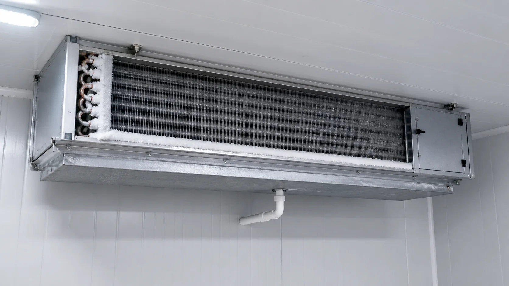
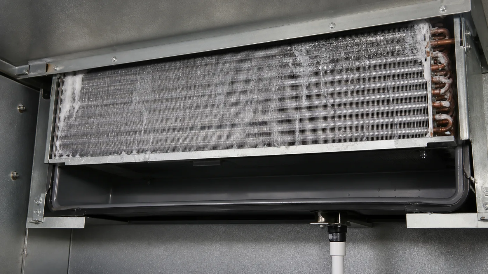
In a medium-temperature cooler, a coil may operate for long periods with limited frost. A freezer evaporator runs with a colder surface, so moisture from infiltration, product loading, door openings, and wet packaging can freeze on the air-side surface. The first frost normally forms where moist return air meets the cold leading edge. As the layer grows, the open air passage becomes smaller, the air-side pressure drop rises, and the fan delivers less useful air.
The relationship is not simply “more space equals more capacity.” A wider fin pitch reduces the amount of metal surface in a given face area. A tighter pitch can increase clean-coil surface, but the gain is temporary if the selected pitch blocks quickly. ASHRAE’s heat-transfer guidance describes fin spacing as a practical balance among fouling, frost formation, condensate drainage, pressure drop, cost, weight, and volume. That is the right framing for an RFQ.
Define the evaporator duty before choosing FPI
Start with the room and product
Record room set point, pull-down target, product temperature, product packaging, door frequency, infiltration control, and expected humidity. A freezer that is opened several times per hour has a different frost load from a sealed process room. A produce room may introduce moisture with the product itself. A blast-freezing application may have high short-term moisture release and high air movement.
Record the refrigerant-side condition
The supplier needs refrigerant or secondary-fluid type, evaporating temperature or saturated suction temperature, design condensing condition, circuiting preference, expected superheat, and defrost pressure or temperature. Do not mix “room temperature,” “coil entering air,” and “saturated suction temperature” in the same field. The temperature difference affects capacity, surface temperature, frost rate, and the time available between defrosts.
Record the air-side condition
Provide entering dry-bulb temperature, relative humidity or dew-point assumption, target leaving temperature, design airflow, allowable air-side pressure drop, and fan operating range. The ASHRAE refrigerated-facility chapter emphasizes that storage temperature, packaging method, and product type affect unit-cooler selection. The coil should be selected against the real air condition, not a clean, dry laboratory point.
Frost, moisture, and air-side pressure drop
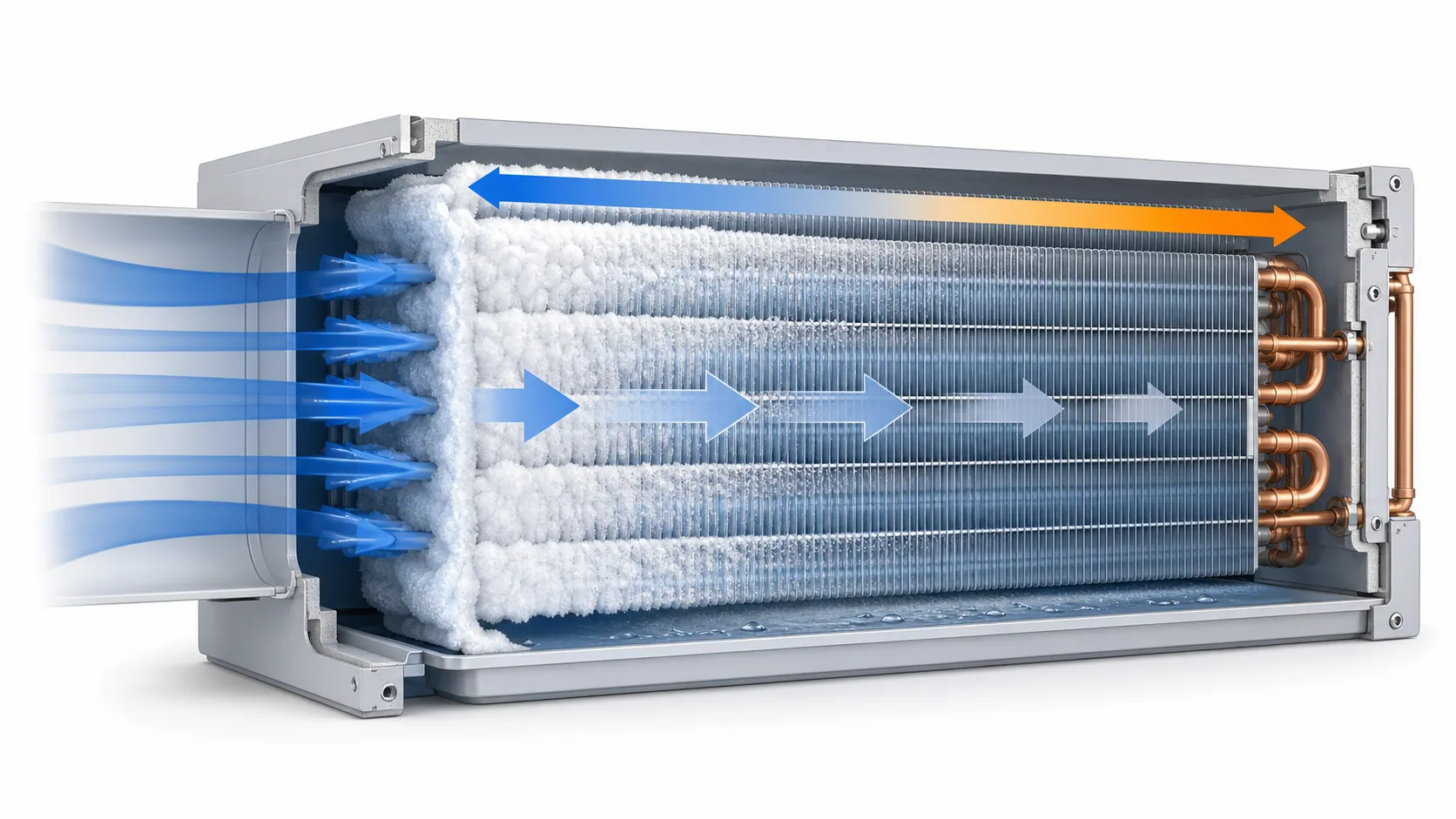
Frost is a growing restriction
Frost occupies the passages between fins. It also changes the roughness and heat-transfer behavior of the surface. In the early period, a thin layer may add surface area. In normal freezer operation, that short-lived benefit is outweighed by blocked passages and lower air volume. A coil that is rated only at clean conditions can look adequate on paper and still fail to maintain room temperature between defrosts.
The leading edge deserves special attention
The inlet face usually sees the highest moisture load. ASHRAE’s retail refrigeration guidance describes staged coils with wider leading-edge spacing so frost can collect without closing the whole face, while a denser trailing section preserves heat-transfer surface. Fin staging is a design option, not an automatic requirement. It should be compared with room airflow, coil depth, and defrost controls.
Air pressure drop affects fan power and capacity
As a coil frosts, the fan operating point moves on its system curve. The result can be lower airflow, less sensible capacity, poorer temperature uniformity, and more frost in low-flow zones. Ask for clean and frosted pressure-drop assumptions if the supplier has them. If they do not, use the design pressure-drop limit as a review gate and validate the selected core during prototype testing.
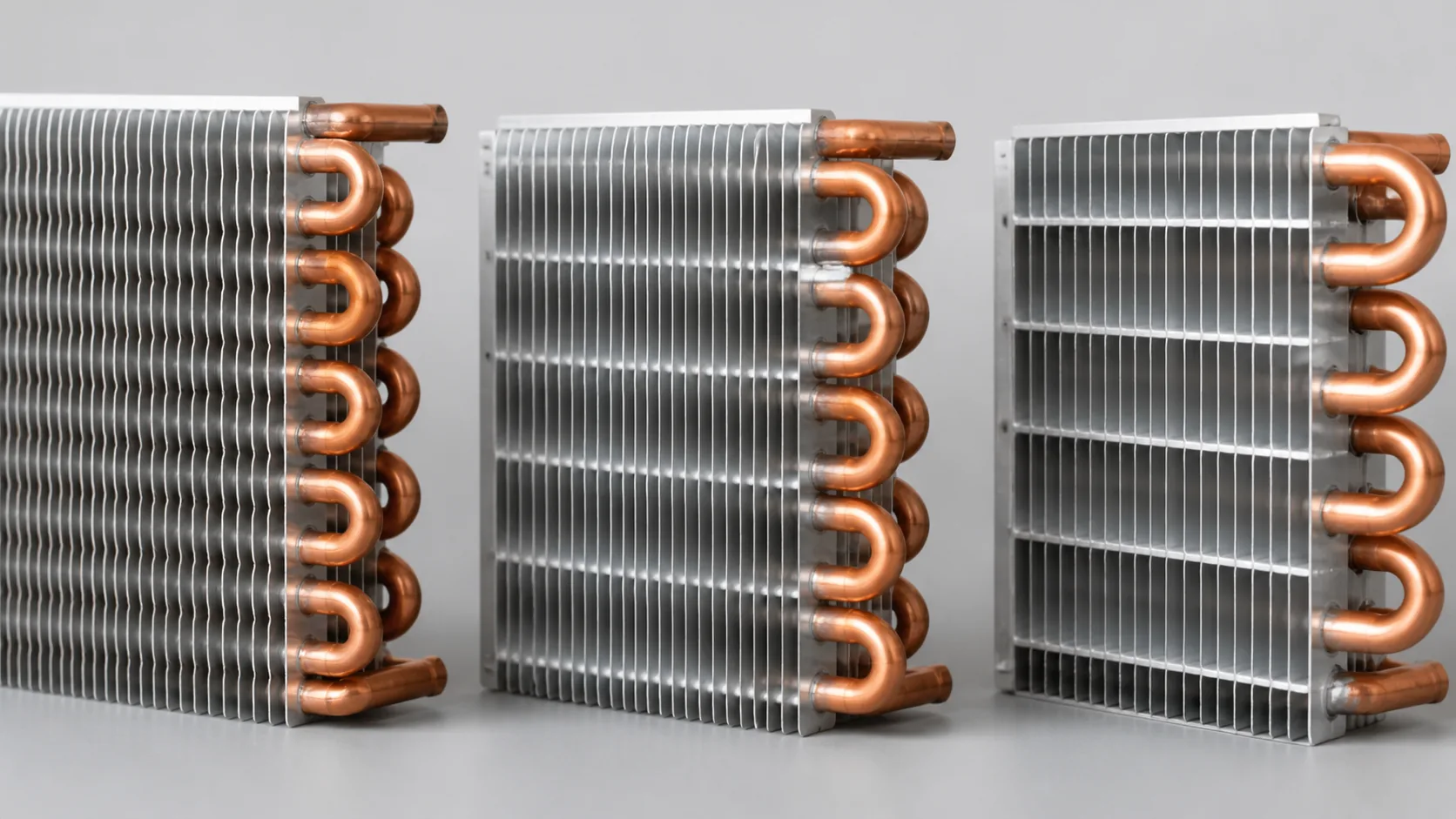
Compare tight, medium, and wide fin spacing
The names below are relative, not fixed industry classes. FPI means fins per inch. Higher FPI means smaller pitch. The actual pitch, fin thickness, louver geometry, tube pattern, and coil depth must be stated on the drawing.
| Spacing approach | Potential benefit | Main risk in low-temperature service | Typical review question |
|---|---|---|---|
| Tighter pitch, higher FPI | More clean-coil surface in a compact face area | Faster airflow restriction when frost, dirt, or wet debris accumulates | Can the fan and defrost strategy hold the required duty after frost growth? |
| Medium pitch | Balanced surface density, pressure drop, and serviceability | May be neither the best compact option nor the best frost-tolerant option | What clean and operating pressure-drop limits are used in the rating? |
| Wider pitch, lower FPI | More open passage for frost, drainage, and washdown | Larger coil or deeper core may be needed for the same clean capacity | Does the cabinet have enough face area and fan throw to recover the surface loss? |
| Staged pitch | More open leading edge with denser downstream surface | More complex tooling, drawing control, and cleaning validation | Is the stage location aligned with airflow direction and defrost drainage? |
Manufacturer catalogs show why a single number should not be copied between projects. For example, Heatcraft product literature lists 3, 4, and 6 FPI options on some large warehouse unit coolers, while other evaporator families list 4, 6, and 8 FPI options. These are product-family choices, not a universal low-temperature rule. Confirm the actual model, refrigerant, defrost, and rating table in the quotation.
Match fin spacing to the defrost method
Off-cycle defrost
Off-cycle defrost can be practical for medium-temperature rooms where the coil surface can rise above freezing during compressor off time. It is generally not the default for a freezer coil with a persistent sub-freezing surface. If a project proposes off-cycle defrost at a low room temperature, ask for a documented frost and recovery test.
Electric defrost
Electric heaters add heat directly to the coil and drain pan. The coil must provide enough clearance for heater installation, wiring, guard components, and drainage. A dense coil may have more trapped ice and require longer heat soak. Confirm heater watt density, termination control, fan delay, drain-pan heat, and the time allowed for the next refrigeration cycle.
Hot-gas defrost
Hot-gas defrost depends on refrigerant flow, pressure, piping, valve selection, and a controlled return path. Coil circuits and headers must be reviewed for even defrosting. ASHRAE’s ammonia refrigeration material notes that defrost temperature and pressure affect heat transfer, steam, and drainage behavior. Do not choose a fin pitch separately from the hot-gas circuit and drain design.
Water or other assisted methods
Water defrost and washdown can increase drainage and sanitation demands. Wider passages may be easier to rinse, but water must not be allowed to refreeze in the pan or drain line. The supplier should state whether the coil, casing, drain pan, and coating are compatible with the cleaning chemistry and temperature.
Airflow, face velocity, and fan selection
Keep the coil and fan on the same duty point
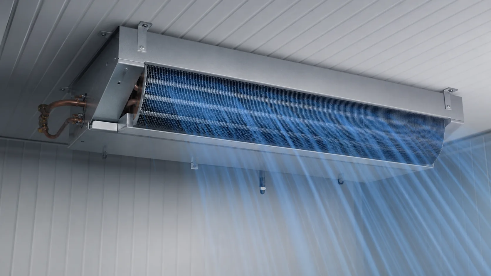
The fin pitch, coil face area, rows, tube pattern, and fan are one air-side system. A change in pitch changes pressure drop and may change the fan motor size. Verify the design airflow at the fan’s actual static pressure, not at free air. Check distribution across the face, because a dry section beside an iced section can hide a local maldistribution problem.
Consider air throw and product sensitivity
High air velocity can improve mixing but may dry or damage exposed product. Low velocity may reduce fan power but allow temperature stratification and local frosting. State the acceptable discharge temperature, throw distance, and product exposure. Link the fin-pitch discussion to the cold-room evaporator fan selection guide when the fan is being sourced separately.
Check the coil at end of cycle, not only at start
The important point is often the end-of-run condition before defrost. Ask the supplier to show expected capacity, airflow, and pressure drop at the selected rating point and to explain what margin is assumed for frost. If the supplier only provides a clean-coil capacity, mark the frost condition as an engineering review item rather than treating it as a guarantee.
Construction, materials, and coating boundaries
Tube and fin materials
Copper tube with aluminum fins is common in air-cooled evaporators, but aluminum tube and fin, copper fin, coated fins, and stainless housings may be used for specific environments. Material selection affects heat transfer, brazing, galvanic compatibility, cleaning, weight, and cost. Do not change tube or fin material while keeping the original rating without a fresh review.
Coating and corrosion exposure
Coatings can help in corrosive or washdown environments, but they add surface resistance and need a cleaning-compatibility review. Define the exposure, chemical, concentration, temperature, rinse method, and expected service interval. Domi’s commercial refrigeration coil coating guide covers the separate corrosion-protection decision. Keep the coating discussion separate from the fin-spacing decision so the RFQ does not hide one inside the other.
Casing and drain pan
The coil may perform correctly and still fail in the field if the casing, drain pan, heater guard, access panel, or slope is wrong. State material, insulation, service side, drain outlet, defrost heater arrangement, and clearance. For food or washdown applications, include the boundary between the product zone and the mechanical zone.
A practical selection matrix
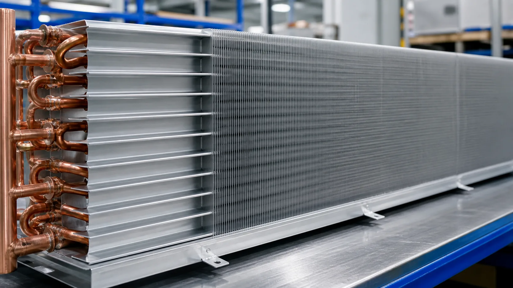
Use the matrix as a conversation starter, not as a capacity rating. The supplier should replace the qualitative entries with a model-specific selection and drawing.
| Application condition | Spacing direction to investigate | What must be checked next |
|---|---|---|
| Sealed freezer, low infiltration, controlled humidity | Medium or tighter pitch may be feasible | Clean and operating pressure drop, fan curve, frost test interval |
| Frequent door openings or wet product loading | Wider pitch or staged leading edge | Frost accumulation, air distribution, defrost time, drain recovery |
| Low air velocity and high humidity | Wider pitch often deserves priority | Coil face area, room pull-down, temperature uniformity |
| Aggressive washdown or frequent cleaning | Wider passage and service access | Coating, fin durability, drain-pan slope, chemical compatibility |
| Compact cabinet with strict face area | Tighter pitch or deeper coil may be considered | Fan power, defrost clearance, frost bridging, noise |
| Hot-gas defrost with complex circuiting | Any pitch only after circuit review | Defrost balance, return piping, trapped liquid, drain time |
For general capacity and face-velocity inputs, use the commercial refrigeration coil sizing guide. It is a sizing aid, not a substitute for the final manufacturer rating.
How to specify fin spacing in an RFQ
Write the requirement so that another engineer can reproduce the selection. “Freezer coil, 6 FPI” is not enough.
| RFQ field | Example of useful information |
|---|---|
| Application | Walk-in freezer, blast freezer, process room, display case, or other |
| Room duty | Set point, pull-down, product load, door schedule, infiltration assumption |
| Air side | Entering temperature, RH or dew point, leaving temperature, airflow, allowable pressure drop |
| Refrigerant side | Refrigerant or fluid, SST or entering fluid temperature, design condensing condition, superheat |
| Fin requirement | FPI or fin pitch, fin thickness, material, louver or plain fin, staged pitch if required |
| Coil geometry | Face area, rows, tube OD, circuiting, headers, connections, casing depth |
| Defrost | Off-cycle, electric, hot gas, water, frequency, termination, fan delay, drain heat |
| Service environment | Washdown, chemical exposure, food boundary, corrosion exposure, access side |
| Evidence requested | Rating table, pressure drop, drawing, material callout, prototype plan, inspection record |
If you are replacing a coil, attach the existing drawing, nameplate, photographs, connection measurements, fan model, defrost details, and any frost-pattern photographs. The custom refrigerator coil RFQ checklist is a useful companion for collecting the rest of the dimensional and operating data.
Prototype and validation checks
Confirm dimensions and assembly
Check face dimensions, row depth, tube OD, fin pitch, circuiting, header orientation, mounting points, drain outlet, heater clearance, and service access. A drawing review should identify the airflow direction and the leading edge.
Measure clean-coil performance
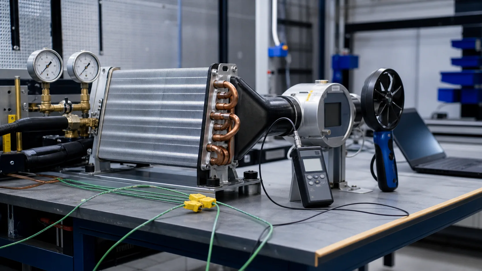
At the agreed refrigerant and air conditions, record capacity, entering and leaving air temperature, airflow, air-side pressure drop, suction pressure, superheat, and fan power. Use the same instruments and uncertainty limits for supplier and buyer data.
Observe frost growth and defrost recovery
Run a representative humidity and infiltration profile. Photograph or document frost distribution, airflow decay, pressure-drop increase, fan current, and time to defrost termination. After defrost, verify that the coil, pan, and drain line clear without residual ice that will become the next cycle’s restriction.
Review serviceability
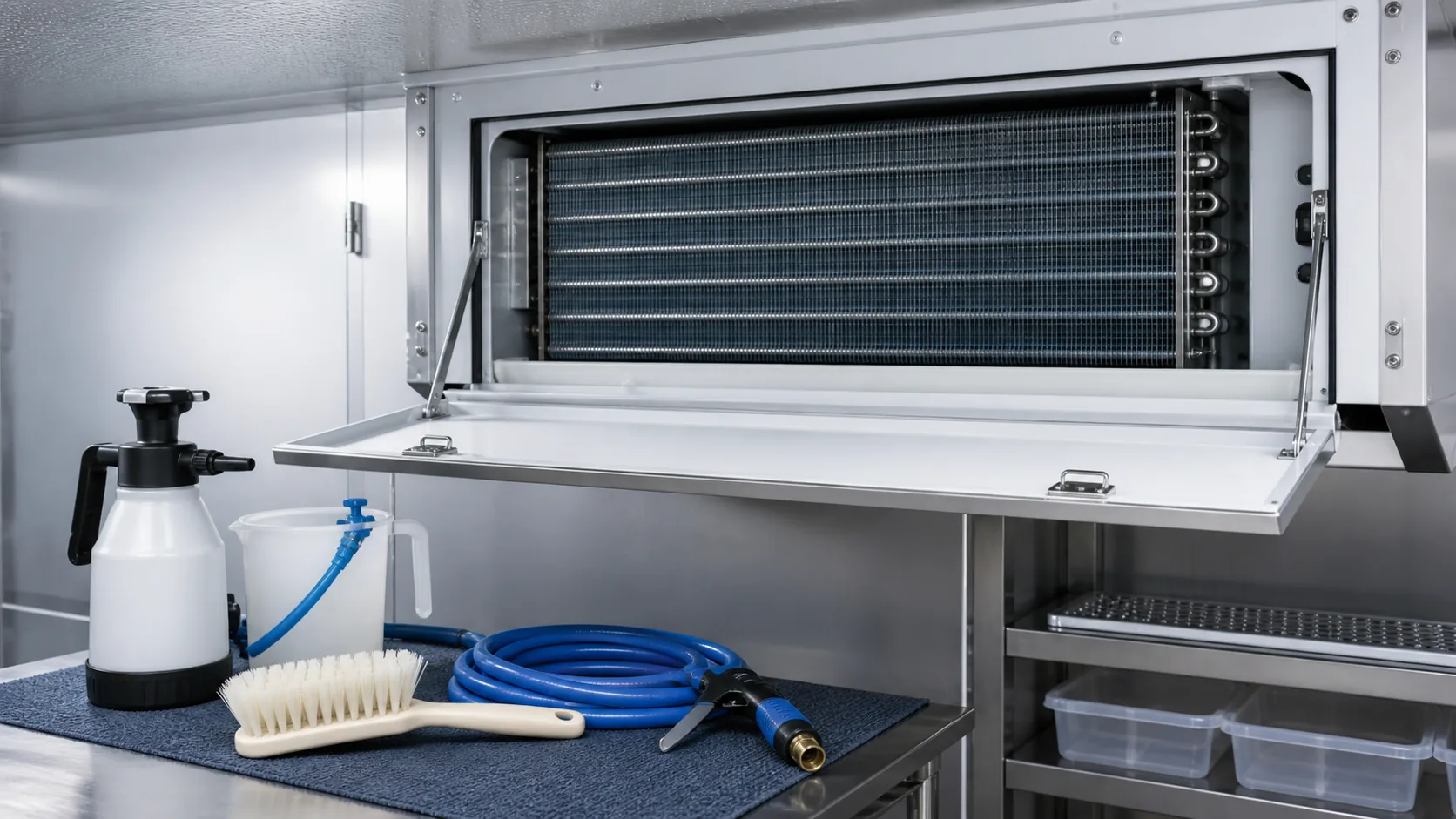
Confirm that the selected pitch can be cleaned without flattening fins, that the access panel can be opened in the installed envelope, and that the drain pan can be inspected. ASHRAE food-service guidance distinguishes typical medium-temperature and low-temperature defrost arrangements, which is a useful reminder to review maintenance with the operating team.
Common procurement mistakes
Copying FPI from a nearby model
The neighboring model may have a different refrigerant, fan, defrost method, face area, or rating point. Use its pitch only as a starting hypothesis.
Comparing capacity without frost assumptions
A clean-coil rating is not an end-of-cycle freezer rating. Ask what frost condition, defrost schedule, and air-side pressure-drop limit were used.
Ignoring the leading edge
A uniform pitch can be acceptable, but a wet or frequently opened room may need a staged design. Ask whether the supplier reviewed the inlet-face frost pattern.
Treating coating as a capacity upgrade
A corrosion coating may improve durability in a particular environment, but it is not a free capacity increase. Review coating thickness, surface resistance, cleaning compatibility, and test evidence.
Leaving the RFQ without a drawing gate
Require a drawing or data sheet that states FPI, fin material, fin thickness, tube material, row count, circuiting, face area, and defrost clearances. A verbal “wide fin” description is not a manufacturing requirement.
Discuss a custom low-temperature evaporator with Domi
Send the room condition, refrigerant, airflow, defrost method, cabinet envelope, target capacity, and any existing drawing or frost photographs. Domi can use the information to review a custom coil concept, identify missing inputs, and return a drawing-led quotation for buyer review. Use the custom coil fabrication page for the manufacturing scope and the OEM partnership program when the project includes prototype approval or repeat production.

Frequently asked questions
Is wider fin spacing always better for a freezer evaporator?
No. Wider spacing can slow blockage and improve drainage, but it reduces clean surface density. The correct pitch depends on frost load, face area, airflow, defrost, and the required end-of-cycle capacity.
What does FPI mean on an evaporator drawing?
FPI means fins per inch. Higher FPI means the fins are closer together. A drawing should also state the actual pitch, fin thickness, material, and fin style because FPI alone does not define the air-side surface.
Can I use condenser fin spacing for a low-temperature evaporator?
Not without review. A condenser rejects heat in a warmer, usually drier air condition. A freezer evaporator may accumulate frost and needs a different pressure-drop, drainage, and defrost evaluation.
Does a staged leading edge replace a defrost system?
No. Staged spacing can delay airflow blockage and distribute frost, but it does not remove the frost load. The defrost method, termination, fan delay, pan heat, and drain must still be designed and tested.
What should I ask a supplier to show with the quotation?
Ask for a drawing, fin pitch and material, coil rows and circuiting, rated capacity, airflow, clean pressure drop, refrigerant conditions, defrost arrangement, casing and drain details, and the assumptions behind any frost or operating margin.
Can a coil be re-pitched during replacement without changing the cabinet?
Sometimes, but not automatically. Re-pitching can change capacity, pressure drop, weight, heater clearance, tube length, circuiting, and fan operating point. Treat it as a new selection and confirm the assembly dimensions before release.