When a refrigerator is not cooling but the freezer works, the first diagnostic focus is cold-air distribution: evaporator airflow, vents, return paths, damper operation, frost accumulation, and control logic.
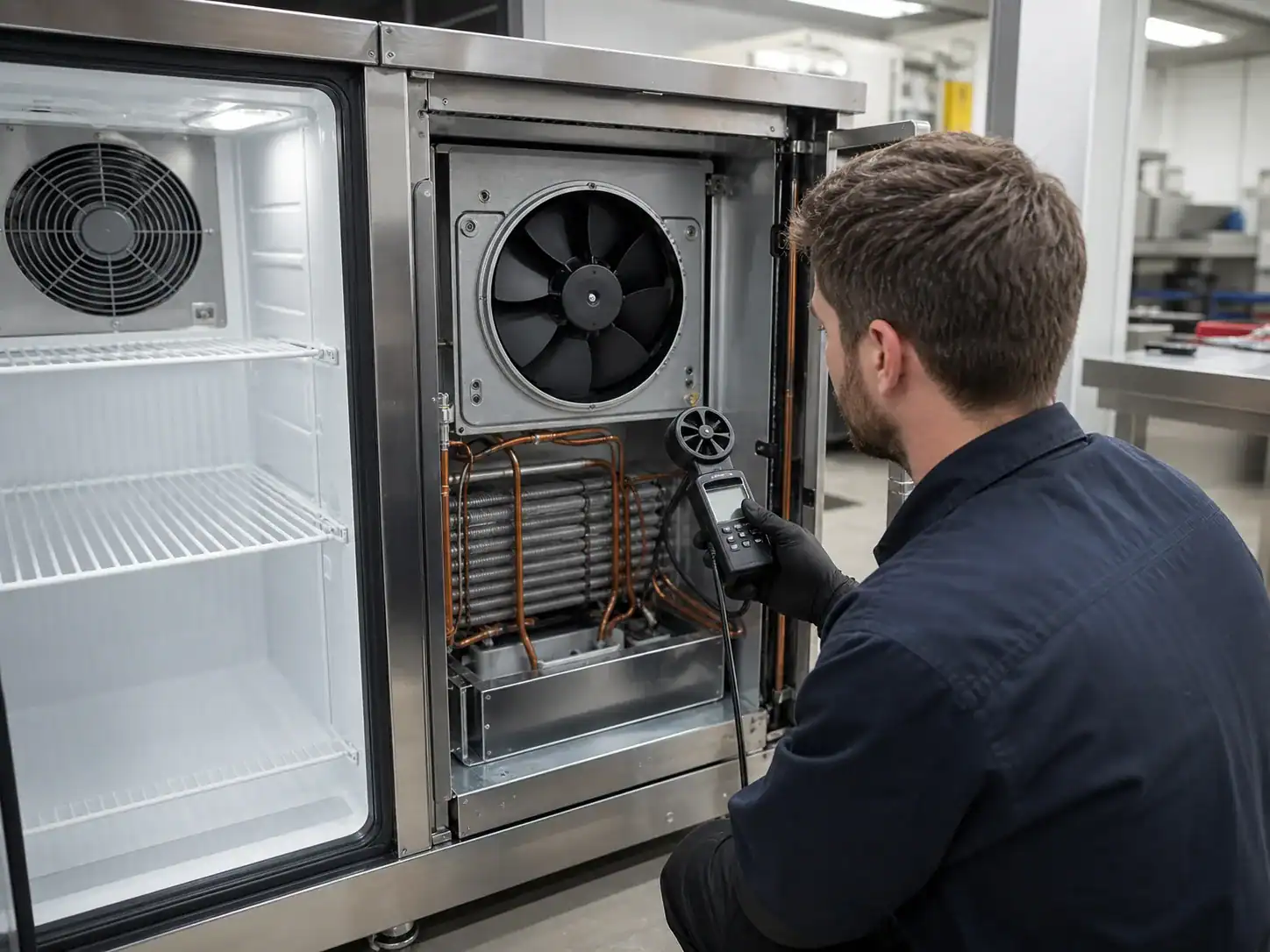
The symptom “refrigerator not cooling but freezer works” is common because many refrigerator-freezer designs generate cooling in one evaporator zone and distribute that cold air to another compartment. The freezer can therefore remain near its target temperature while the fresh-food compartment becomes warm. The fault may be a fan, damper, blocked vent, return-air restriction, ice buildup, sensor, control, or door-seal problem. It is not automatically a failed evaporator coil.
This guide separates the fresh-food airflow problem from a full sealed-system failure. It is intended for service teams and for OEM engineers specifying evaporators, air channels, defrost components, and replacement parts. Low-risk observations are suitable for basic triage. Electrical measurements, disassembly, refrigerant work, and repairs that affect food safety should follow the appliance instructions and be performed by a qualified technician.
The Whirlpool manufacturer troubleshooting guide illustrates a sensible starting point: confirm settings, power, airflow, door closure, and installation conditions before assigning a sealed-system fault. The ENERGY STAR refrigerator guidance also emphasizes air circulation and clean condenser areas. For a product team, those service checks should be connected to the approved cabinet, coil, fan, damper, and defrost design.
What the symptom tells you—and what it does not
If the freezer is genuinely cold, some refrigeration capacity is being produced. That makes a complete compressor failure less likely, but it does not prove that the evaporator, charge, circuiting, or controls are healthy. A freezer may appear cold because it has less load, a colder setpoint, better insulation, or a local cold spot near the evaporator.
Confirm both compartments with a measured temperature
Do not use one item of food or a hand on the interior wall as a temperature test. Record air and product temperatures in the freezer and fresh-food compartment, the setpoints, time since a door opening, ambient temperature, and the location of each probe.
| Check | Useful observation | Diagnostic meaning |
|---|---|---|
| Freezer air temperature | Within or outside approved range | Confirms whether the cooling source is producing the expected condition |
| Fresh-food air temperature | Warm at all shelves or only one zone | Shows whether distribution or loading is localized |
| Supply vent | Cold air present, weak, intermittent, or absent | Direct evidence of fan, damper, ice, or duct restriction |
| Return vent | Open, blocked, iced, or noisy | A return restriction can stop circulation even with a working fan |
| Evaporator frost | Even, partial, solid, or absent | Helps separate airflow/defrost from sealed-system concerns |
| Fan and damper | Sound, movement, vibration, position | Confirms physical response, not just electrical command |
If the fresh-food compartment is warm but the supply vent is cold and strong, inspect mixing, return airflow, sensor location, door-seal leakage, and load distribution. If the supply vent is warm or has no flow, stay on the airflow, ice, control, and evaporator path before ordering a replacement coil.
The airflow path from evaporator to cabinet
Cold air must leave the evaporator, travel through a duct or passage, enter the compartment, mix with the load, and return to the evaporator. A failure at any point can create the same customer complaint.
Evaporator fan failure or weak airflow
The fan may be stopped, iced, noisy, running at the wrong speed, or blocked by a displaced cover. Some designs stop the fan when a door opens, so a test must account for door-switch logic. A fan can also run while moving too little air because of a damaged blade, a reversed replacement, a loose hub, a wrong voltage, or bypass around the shroud.
Check the expected service-test mode and confirm the physical airflow at the outlet. Do not assume that a voltage reading alone proves correct fan performance. For an OEM, specify fan direction, shroud clearance, outlet area, bypass seals, and the acceptable airflow range together with the evaporator drawing.
Damper or air valve failure
In a multi-compartment refrigerator, a damper meters cold air into the fresh-food compartment. It can be stuck closed, blocked by ice, misaligned, noisy, slow, or commanded incorrectly by a sensor or control board. The damper may look open while an internal flap is not sealing or moving through its full range.
Record the commanded position and actual position. If the control uses a thermistor to regulate the damper, test the sensor and the wiring at the relevant temperature. A replacement damper must match connector, travel, seal, noise, and control behavior; it is not interchangeable only because the outside housing fits.
Supply or return vent obstruction
Food containers, packaging, ice, a shifted duct liner, insulation, or a mispositioned shelf can block the supply or return path. Warm air can accumulate at the top or rear while the lower area remains closer to target. Review the entire air path, not only the visible outlet.
An OEM design review should show the keep-clear zone, grille opening, duct section, fan pressure, and return path. The Domi refrigeration coil drawing revision-control guide explains why changes to a bracket, cover, opening, or sensor location should be tied to a controlled revision when they affect the approved part interface.
Ice and defrost causes
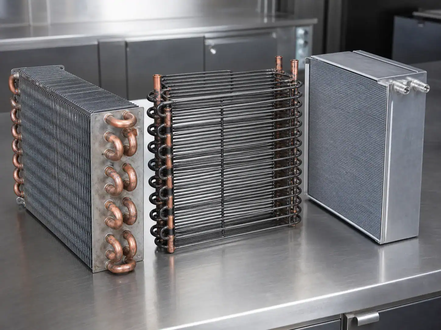
A freezer can keep food frozen while ice gradually blocks the evaporator and stops air from reaching the fresh-food compartment. The complaint may improve after a complete defrost, then return when the frost accumulates again.
Solid frost across the evaporator
A thick, continuous frost layer reduces the open fin area and increases air-side resistance. The fan may still run, but the pressure drop becomes too high for the intended airflow. The coil can also become a physical ice block that stops the fan blade or closes the duct.
Do not chip ice with a sharp object or apply uncontrolled heat. Follow the appliance service instructions. After the ice is removed safely, determine whether the defrost heater, thermostat or sensor, control command, termination, drain, and door moisture load are correct. The GE automatic-defrost information describes the basic purpose of automatic defrost and why the evaporator needs periodic frost removal.
Defrost heater and sensor interface
The heater must deliver enough heat to clear the coil within the allowed time while avoiding damage to insulation, food-zone components, wiring, or plastic parts. A thermostat or sensor must be located where it sees the right thermal condition. If a replacement evaporator moves the sensor clip or heater position, the defrost cycle can change even when the coil still produces capacity.
For an OEM coil drawing, identify heater clearance, sensor contact, clip position, drain route, and the approved defrost test. If Domi’s scope for a specific component is not confirmed, treat the heater and thermostat as system interfaces requiring project review; do not assume a coil quotation includes those controls.
Drain blockage and refreezing
Meltwater must leave the coil area. A blocked drain or incorrect slope can allow water to refreeze below the evaporator and grow into the airflow path. Inspect the drain design, pan, heat transfer or drain-heater provision, insulation, and service access. A coil replacement that ignores a recurring drain problem will not be a durable correction.
Door seals, moisture, and load conditions
Fresh-food temperature can rise when warm, humid air enters through a damaged gasket, a misaligned door, a cabinet twist, or frequent opening. Moisture then freezes around the evaporator or vents and adds heat load. Product can also block a return path while the freezer appears normal.
The U.S. Department of Energy refrigerator efficiency guidance explains why location, clearance, seals, and operating conditions influence refrigerator performance. For service, inspect the gasket contact around the complete perimeter, not only the visible corner. For product design, define gasket compression, door alignment, liner tolerances, and the intended shelf or bin loading.
A simple load and airflow review
Ask whether the symptom appears empty, normally loaded, or fully loaded. Check whether a large warm load was added recently, whether the door was left open, whether the cabinet is in a high-ambient location, and whether packages are pressed against the rear wall or vents. These conditions may explain a temporary temperature rise but should not be used to dismiss a persistent failure.
| Condition | What to compare | Possible action |
|---|---|---|
| Empty cabinet warm | Airflow and control response | Confirm fan, damper, frost, and temperature sensors |
| Normal load warm | Supply and return air at several shelves | Look for distribution or loading restriction |
| Warm only after large load | Pull-down time and compressor run time | Verify capacity and control recovery |
| Warm after door openings | Seal, gasket, and humidity | Check door alignment and moisture entry |
| Warm at high ambient | Condenser temperature and airflow | Review clearance, fan, and capacity margin |
Frost pattern and sealed-system checks
A working freezer can still have a charge or restriction problem. If the evaporator frost pattern is absent, very small, or limited to the inlet while the compressor runs, a qualified technician should evaluate pressures, temperatures, leak evidence, restrictions, compressor performance, and the actual circuiting. A partial pattern is a clue, not a diagnosis.
The Danfoss cold-room troubleshooting resource organizes fault diagnosis around system conditions such as evaporator, condenser, airflow, defrost, and refrigerant-side performance. Use the appliance manufacturer’s procedure and the refrigerant’s applicable safety and service requirements.
Why a new evaporator may not solve the complaint
Replacing the evaporator can fail to correct the symptom when:
- The evaporator is intact but the fan is stopped or weak.
- A damper or duct is closed, iced, or misaligned.
- A return-air path is blocked by food, ice, or liner geometry.
- A defrost sensor or control fails again after the coil is installed.
- A drain freezes and returns water to the air path.
- The sealed system has a leak, restriction, incorrect charge, or compressor issue.
Before releasing a replacement coil, record what test failed and why the coil is implicated. This protects the buyer from unnecessary cost and gives the supplier the evidence needed to review the design.
OEM coil and cabinet design considerations
The symptom is especially valuable during a product program because it can show where the component interface is underspecified.
Define the evaporator air-side requirement
Include face area, fin pitch, tube pattern, circuiting, air velocity or airflow, bypass gap, fan operating point, frost allowance, defrost condition, sensor position, and cover geometry. A coil that meets a laboratory capacity at an open test stand may not deliver the same cabinet result if the duct has leakage or the fan operates at a different pressure.
Plan for frost and defrost together
Design the fin pack, drain, heater, sensor, cover, and control strategy as a set. Review where frost starts, how it affects pressure drop, how meltwater exits, and how much time the cabinet needs to recover after defrost. The Danfoss industrial refrigeration defrost handbook provides useful system-level context for defrost choices and operational trade-offs, although the appliance-specific acceptance limits must come from the product design.
Preserve service interfaces
Show how the technician accesses the fan, coil, heater, sensor, drain, cover, and connector. If a coil revision changes a clip or mounting point, record the change in the drawing, service manual, inspection plan, and replacement part list. If a component is not part of the supplier’s confirmed scope, mark it as a customer-supplied or project-reviewed interface.
Validate the cabinet, not only the part
Test pull-down, steady-state temperature, door-opening recovery, frost accumulation, defrost recovery, noise, drain behavior, and high-ambient performance. Record the airflow and sensor locations. Review more than one cabinet if tolerances, fan speed, or loading can vary.
How to identify a replacement evaporator for this symptom
Send the supplier the appliance model and serial family, existing coil part number, latest drawing revision, photographs, envelope, mounting, tube and connection details, circuiting, refrigerant, design pressure, capacity, airflow, defrost hardware, sensor and heater interfaces, materials, finish, testing, packaging, volume, MOQ, sample count, and target date. A physical sample can help, but it does not replace required operating data.
The Domi evaporator-coil quotation information guide lists the engineering and commercial inputs that make a quote reviewable. For a new residential coil program, the residential refrigeration coil product page is the appropriate starting point for an OEM discussion. If the project is a replacement rather than a new design, include old-revision history and service feedback so the supplier does not reproduce a known interface problem.
| RFQ group | Information to send |
|---|---|
| Application | Appliance type, compartment, setpoint, ambient, load, duty cycle |
| Air side | Fan, shroud, duct, face area, airflow, fin pitch, frost allowance |
| Refrigerant side | Refrigerant, tube size, circuiting, connection orientation, pressure and test data |
| Defrost | Heater, thermostat or sensor, clip, drain, termination and recovery requirements |
| Fit | Envelope, brackets, holes, cover, insulation, keep-outs and service access |
| Quality | Leak/pressure test, dimensional report, appearance, cleanliness, change approval |
| Commercial | Sample quantity, annual volume, MOQ, packaging, lead time and destination |
A repeatable test protocol for the freezer-works symptom
For an OEM or service organization, the quality of the conclusion depends on repeatability. Use a defined cabinet condition rather than a one-time observation at an unknown point in the compressor cycle.
Establish the baseline
Record the model, serial family, software or control revision, ambient temperature, cabinet loading, setpoints, door condition, and time since the last door opening. Let the appliance operate for the defined period before taking steady-state readings. If the product cannot reach the test condition, record the elapsed run time and the reason for ending the test.
Measure both compartments at more than one location where the test plan requires it. Note whether the freezer probe is near the evaporator, a supply outlet, a shelf, or a product package. A freezer reading taken at a cold wall can look normal while the average compartment temperature is high.
Map the air path
With the appliance in the approved test mode, record supply-air temperature, return-air temperature, airflow or velocity if available, fan state, damper state, and the temperature at representative shelves. Mark the supply and return locations in the test record. If the air path uses a recirculation fan, note noise, vibration, and any visible ice.
The air map can show three different patterns:
| Air-map pattern | Interpretation to investigate |
|---|---|
| Supply cold and strong, cabinet uneven | Mixing, return path, loading, gasket, insulation, or sensor location |
| Supply cold but weak or intermittent | Fan, damper, ice, shroud, duct, connector, or control timing |
| Supply warm with weak frost | Coil, charge, restriction, compressor, or control condition |
| Supply warm with heavy ice | Defrost, fan blockage, drain, humidity, or cover condition |
| Supply normal only during service test | Control logic, sensor input, timer, or operating-mode issue |
Do not set acceptance criteria from a generic airflow number. The correct value depends on fan curve, fin density, duct resistance, cabinet volume, refrigerant duty, and the product’s temperature uniformity requirement.
Run a controlled defrost observation
When ice is suspected, record the starting frost pattern and the defrost command. Verify the heater or other approved defrost method, sensor or thermostat response, termination, maximum cycle time, meltwater path, and return to cooling. If the coil cover prevents direct observation, use the service procedure and temperature or current evidence rather than opening the sealed cabinet unnecessarily.
The GE defrost thermostat information is a useful reminder that a thermostat is a temperature-protection and control-interface component, not simply a generic switch. Part compatibility depends on the model, temperature range, mounting, connector, and circuit. For a custom coil, show the thermostat or sensor attachment location and the clearance around the heater if those interfaces are in scope.
Confirm recovery after defrost
A successful defrost test is not complete when the ice disappears. Verify that the drain clears, the fan restarts, the damper returns to the expected state, the cabinet reaches its target again, and no new ice forms at a duct or low point. Record recovery time and any temperature overshoot. This step is important because a coil can look clean while a drain or sensor placement continues to create a recurring complaint.
Failure modes that look like the same complaint
The following distinctions help service and procurement teams use the keyword symptom without overgeneralizing it.
One compartment warm, one compartment normal
Start with distribution and control. Compare fan, damper, vents, return, frost, sensor, and door conditions. A replacement coil is not the first conclusion unless the evaporator evidence also shows a physical or sealed-system defect.
Both compartments gradually warm
Check compressor run state, condenser heat rejection, evaporator frost, airflow, charge, restriction, and control. A dirty condenser or high ambient can reduce capacity; a partial frost pattern can indicate sealed-system or circuiting issues. Use qualified service measurements.
Cooling returns after power cycling
Power cycling can reset a control or change a damper or fan state, but it does not repair a blocked coil, leak, or failed heater. Record which component changed state and whether the temperature improvement is repeatable.
Cooling returns after manual defrost
This pattern strongly suggests an ice or defrost path, but the test should continue through a complete cycle. Check heater, sensor or thermostat, control command, drain, fan, door seal, and moisture entry. If the coil repeatedly ices at one location, review airflow bypass, sensor placement, and drain geometry.
Freezer is cold only near the rear wall
A local cold surface does not prove the freezer average is in range. Measure the compartment, inspect the evaporator frost, and verify air circulation. A partial frost or low-airflow condition can create a misleading cold spot.
How an OEM should approve a corrective coil revision
If the investigation proves that the evaporator design or assembly is contributing to the symptom, define the change and its effect. Examples include changing fin pitch to manage frost, correcting circuiting, moving a connection, changing a bracket, adding a drain feature, revising a sensor clip, adjusting a cover seal, or improving a coating or material for the intended environment.
The change record should identify:
- The original symptom and measured evidence.
- The part number and old revision.
- The physical and performance feature being changed.
- The expected effect on capacity, airflow, frost, defrost, pressure drop, noise, fit, and service.
- The sample and validation plan.
- The supplier quotation and tooling impact.
- The effective date and disposition of old stock.
- The drawing, test, inspection, service, and packaging documents updated.
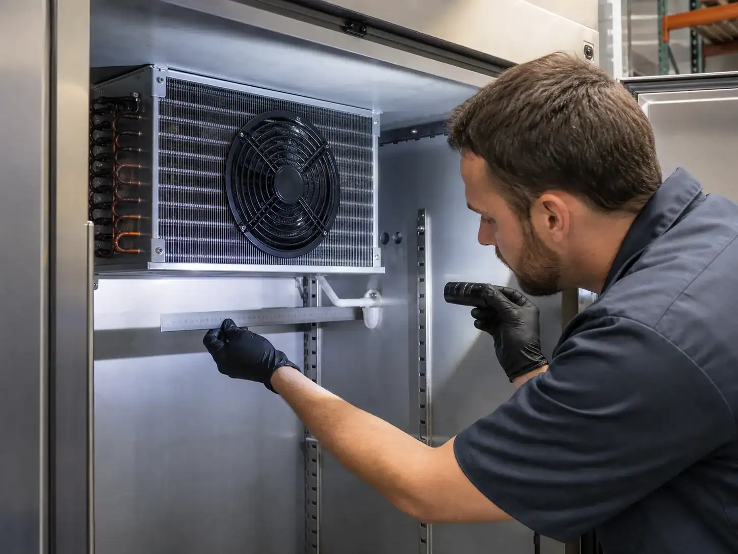
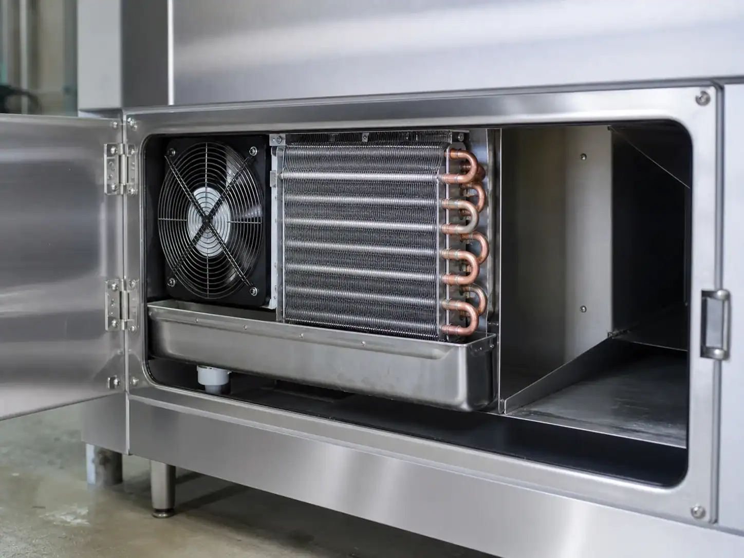
Do not hide a material, refrigerant, pressure, circuiting, or heater-interface change under an editorial revision. Those changes can affect safety, test requirements, qualification, and replacement compatibility.
Before production release, compare an approved sample with the drawing, inspect envelope and connection locations, pressure- or leak-test as specified, verify airflow and defrost interfaces, run cabinet tests, and retain the report with the same revision identifier. The Domi custom refrigeration coil prototype process can be used as an internal-link starting point for sample and drawing coordination.
A supplier review checklist
Ask the supplier to confirm what is included in the quotation and what remains customer-supplied. Clarify whether the price covers the coil only or also brackets, heater, thermostat, sensor clips, fan shroud, insulation, protective caps, testing, packaging, and labels. Confirm the drawing revision, sample timing, production lead time, MOQ, annual volume assumption, change-notification process, and the records delivered with each lot. This avoids a common handoff problem in which a buyer expects a complete evaporator assembly while the quote describes only a bare fin-and-tube component.
Keep the symptom-specific article separate from a general “refrigerator not cooling” investigation because the freezer observation changes the first branch of the diagnosis. The two cases can share a final coil RFQ checklist, but the service form should preserve the distinction between a distribution failure and a system-wide capacity failure. That distinction saves time, reduces unnecessary parts, and gives the product team cleaner evidence for future cabinet revisions.
Close the case with a before-and-after comparison
For a repaired or revised unit, compare the original symptom record with the final test record. Use the same probe locations, ambient range, load, setpoints, and airflow observations. State what changed, which evidence proved the cause, and what part revision was installed. If a manual defrost, fan change, damper adjustment, or coil replacement produced the improvement, record the result separately. This prevents a successful temporary reset from being mistaken for a validated permanent solution and gives procurement a defensible basis for the next service or OEM release.
The handoff should also identify the next owner. Service owns the immediate repair procedure, engineering owns the cabinet or coil change, quality owns the acceptance record, procurement owns the supplier and commercial assumptions, and the service-parts team owns the compatibility note. This division does not need to be complicated; it only needs to be visible. A freezer-works complaint is often repeated because the temporary repair is recorded but the airflow, defrost, or replacement-part lesson never reaches the next product revision.
Turn the symptom into a useful service form
Use separate fields for freezer temperature, fresh-food temperature, supply airflow, return airflow, evaporator frost, fan state, damper state, defrost evidence, door condition, and sealed-system observations. Let the technician mark “not checked” rather than forcing an assumption. Add a place for a photograph of the evaporator and a place to record whether the unit was manually defrosted before the test.
For a replacement request, attach the form to the coil drawing or sample. The supplier can then see whether the requested part is intended to restore a known approved design or correct a problem in the old design. The distinction also protects procurement from ordering a coil when the actual issue is a fan, damper, drain, sensor, or control. Once the repair is complete, repeat the same fields and compare the before-and-after result. This creates a small but useful evidence trail for service, quality, engineering, and future quotation reviews.
Do not confuse a distribution fault with a product safety issue
If food has been above its safe storage temperature, follow the applicable food-safety guidance rather than relying on the smell or appearance of the product. Service diagnosis comes after protecting users and product. Never bypass a safety control or expose a customer to refrigerant, electrical, hot defrost components, or sharp fins.
FAQ: refrigerator not cooling but freezer works
Why is the freezer cold but the refrigerator compartment warm?
The two compartments may share an evaporator but use different airflow paths. A stopped evaporator fan, closed damper, blocked vent or return, ice-covered coil, sensor, control, or door-seal problem can stop cold air from reaching the fresh-food compartment while the freezer remains cold.
Can a refrigerator have a bad evaporator coil if the freezer works?
Yes, but the symptom alone does not prove it. A leak, restriction, damaged tube, or circuit problem can reduce total capacity. Confirm frost pattern and qualified sealed-system measurements, then compare the result with the approved coil design before ordering a replacement.
Does defrosting fix the problem permanently?
It can restore airflow temporarily when ice is blocking the evaporator, but the recurring cause may be a heater, thermostat, sensor, control, drain, gasket, or moisture-load problem. A repeat complaint needs a complete defrost-path diagnosis.
How do I know if the damper is working?
Use the appliance service test and observe both the command and the physical movement. Check the supply airflow, damper position, ice, seal, and control sensor. Do not force the flap or bypass the control as a permanent repair.
Why does the top shelf stay warm while the lower shelf is cooler?
Air distribution, return-air location, loading, duct leakage, or sensor position can create temperature stratification. Measure several zones with the same instrument and verify that vents are clear. An OEM should evaluate fan pressure, duct geometry, and cabinet tolerances.
What should I inspect before buying a replacement evaporator?
Confirm the frost pattern, fan, damper, vents, return path, defrost components, drain, controls, and sealed-system evidence. Then match the coil’s envelope, mounting, connections, circuiting, refrigerant, capacity, airflow, heater and sensor interfaces, test requirements, and revision.
Is a universal evaporator acceptable for an OEM refrigerator?
Only after engineering verifies fit, capacity, pressure, refrigerant, airflow, defrost, control interfaces, materials, service, and validation. A universal part can create uncontrolled variation in a production program.
What should be included in an OEM quote request?
Include the appliance and compartment, drawing or sample, operating conditions, refrigerant, dimensions, mounting, circuiting, connections, airflow, fan and shroud, defrost and drain interfaces, materials, inspection, packaging, volume, MOQ, and timing. Clearly label any missing data.