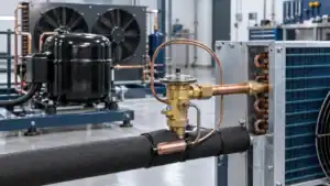
Direct Answer: Chilled water coils are heat exchangers that circulate cold water through copper tubes and aluminum fins to cool air in HVAC systems.
Choosing the wrong chilled water coil can cost you thousands in energy waste and premature equipment failure. Whether you’re specifying coils for a new air handling unit or replacing a failed coil, understanding construction details, performance factors, and application requirements separates efficient systems from costly mistakes. This guide walks you through everything from basic operation to selection criteria used by HVAC engineers.
What Is a Chilled Water Coil?
A chilled water coil is a finned-tube heat exchanger that cools air by circulating chilled water (typically 42–48°F) through copper tubes while air passes over aluminum or copper fins. Think of it as a car radiator working in reverse—instead of rejecting engine heat to air, it absorbs room heat into the water stream.
How Chilled Water Coils Work
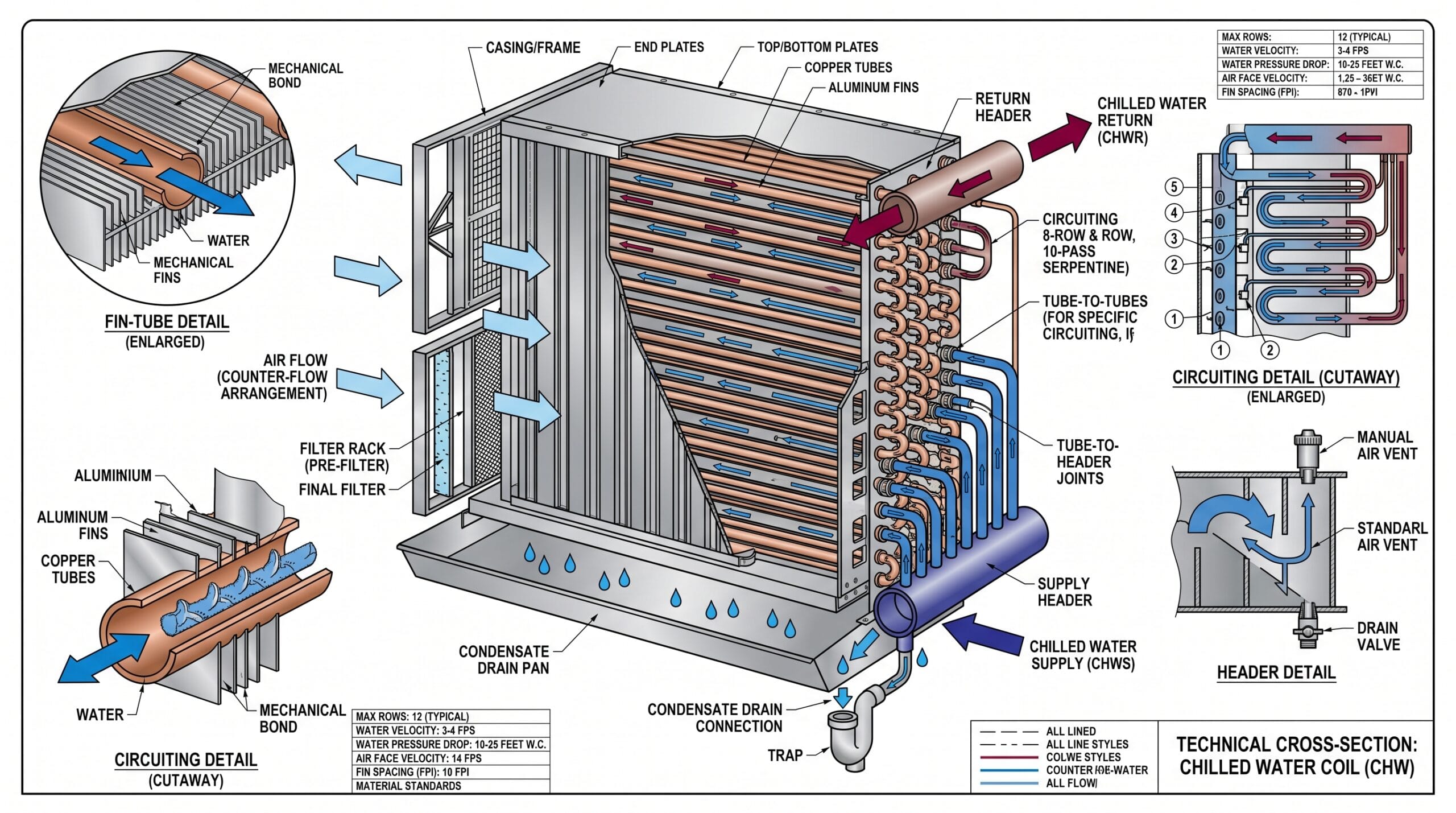
The cooling process relies on two simultaneous heat transfer mechanisms. Cold water enters the coil header and flows through multiple parallel copper tube circuits. As warm air from the space passes across the exterior fin surfaces, heat conducts from the air through the aluminum fins into the copper tubes, then into the flowing water. The water temperature rises by 10–14°F as it absorbs this heat, then returns to the central chiller to be cooled again. Air velocity across the coil face typically ranges from 400–500 feet per minute (FPM) in commercial applications. Higher velocities increase heat transfer but also raise pressure drop—the resistance that your air handler fan must overcome. This is why proper coil selection balances cooling capacity against fan energy consumption. Water flow rate through chilled water coils is measured in gallons per minute (GPM). A typical commercial coil might flow 40–60 GPM with a 10°F temperature rise. The relationship is simple: higher flow rates increase heat transfer efficiency but require larger pumps and piping. Most systems are designed for a 10–14°F temperature differential between entering and leaving water, which optimizes chiller efficiency.
Key Components and Construction
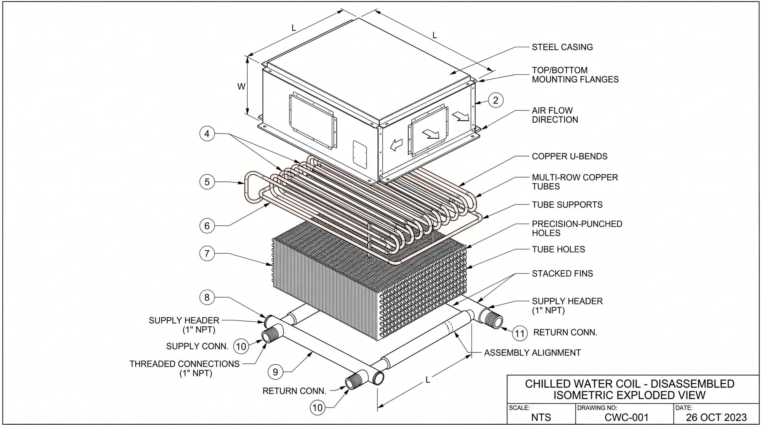
Every chilled water coil consists of four primary elements that determine its performance and longevity. Tubes form the water-carrying circuits. Industry-standard construction uses seamless copper tubes conforming to ASTM B75 specifications—typically UNS C12200 copper alloy in 0.5″ or 0.625″ diameter. The tubes are arranged in rows (depth perpendicular to airflow) and circuits (parallel water paths). Seamless construction eliminates the weak points that cause premature failures in welded tubes. Fins provide the air-side heat transfer surface. Aluminum fins are most common due to their excellent thermal conductivity and low cost. Each fin is die-formed with collars that grip the copper tubes when mechanically expanded during manufacturing. Fin density ranges from 8 fins per inch (FPI) for industrial applications to 14 FPI for clean environments. The fins may be flat, waffle-pattern, or sine-wave design depending on the performance requirements. Headers are the manifolds at each end of the coil that distribute water to the tube circuits. These are typically constructed from the same C12200 copper as the tubes, sized to match the connection diameter (usually 1″ to 4″ depending on coil capacity). Quality headers feature spin-closed ends designed to withstand test pressures of 300–550 PSIG. Small vent and drain ports (typically 1/4″ NPT) allow for air purging and winterization. Casing surrounds the coil assembly and provides structural support. Standard construction uses 16-gauge galvanized steel with double-flanged edges that allow vertical stacking of multiple coils. The casing also includes intermediate tube supports on coils longer than 50 inches to prevent tube sagging under water weight. According to AHRI Standard 410, all water coils with 0.5″ or 0.625″ tubes must be performance certified and bear the AHRI symbol. This certification guarantees that published capacity ratings match actual tested performance within acceptable tolerances.
| Feature | Chilled Water Coil | DX Coil | Evaporative Cooler |
|---|---|---|---|
| Cooling medium | Chilled water | Refrigerant | Water evaporation |
| Temperature control | Precise (±2°F) | Moderate | Poor (ambient-dependent) |
| Energy efficiency | High (central chiller) | Moderate | Very high |
| Maintenance | Low | Moderate (refrigerant) | High (water treatment) |
| Installation cost | $$$$ | $$ | $ |
| Dehumidification | Excellent | Excellent | None |
Types of Chilled Water Coils
Chilled water coils are categorized by tube rows (3–12 rows), fin density (8–14 FPI), and configuration (cased, uncased, or cleanable sectional). Each variation serves specific applications based on cooling load, humidity removal needs, and maintenance requirements.
By Tube Row Configuration
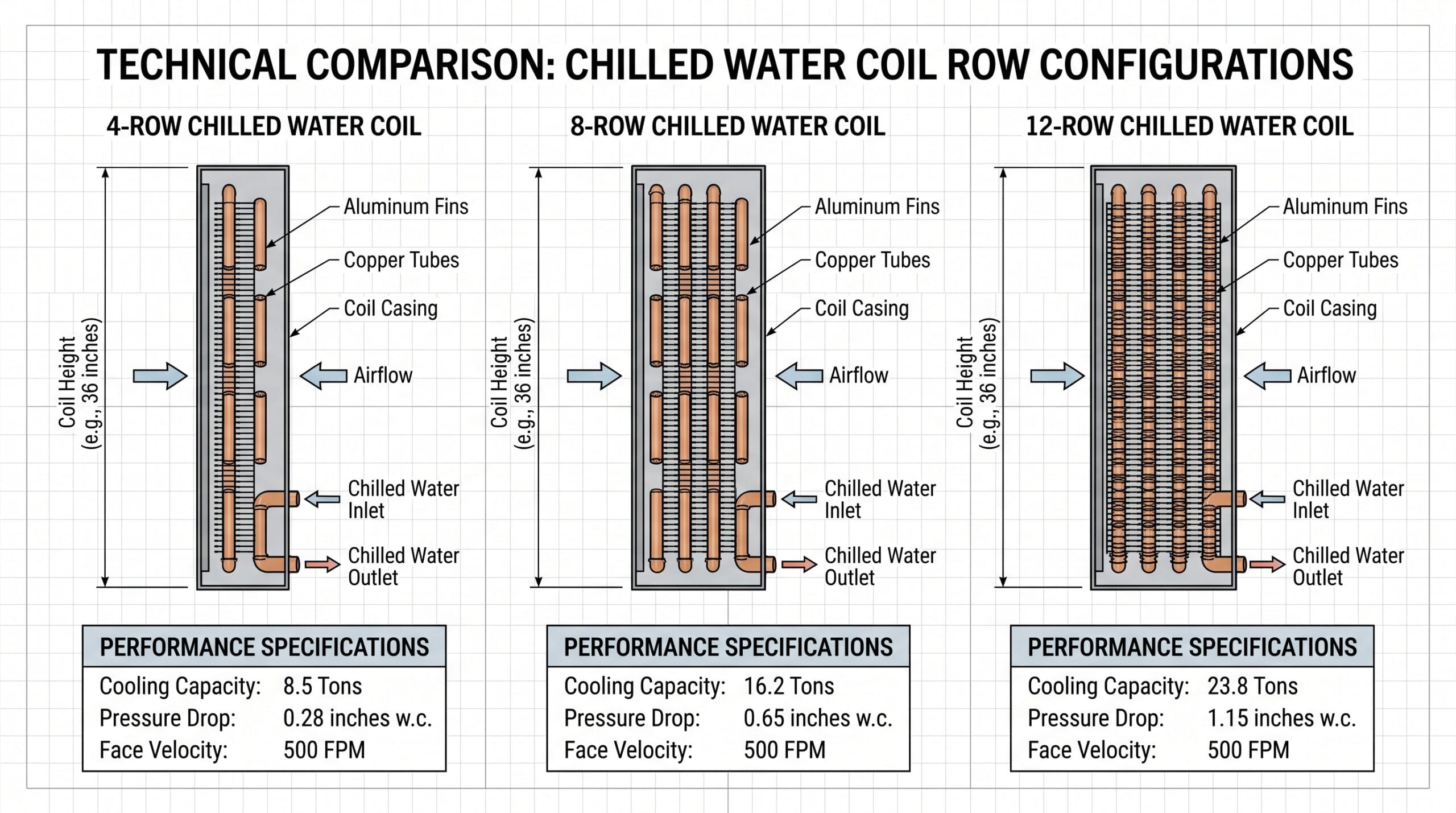
Row depth directly determines cooling capacity and the coil’s ability to remove moisture from the air. More rows mean more surface area for heat transfer—but also higher air pressure drop and cost. 3–4 row coils suit light-duty applications with modest cooling loads. You’ll find these in small fan coil units, perimeter heating/cooling units, and spaces where humidity control isn’t critical. A 4-row coil in a typical office might handle 3–5 tons of cooling capacity. The shallow depth keeps pressure drop under 0.3 inches of water column, minimizing fan energy. 6–8 row coils represent the commercial HVAC standard. These handle the bulk of office buildings, retail spaces, and light industrial facilities. An 8-row coil provides enough surface area for both sensible cooling and dehumidification without excessive pressure drop. We typically see 0.4–0.6 inches of water column across an 8-row coil at 450 FPM face velocity, which is easily handled by standard air handler fans. 10–12 row coils come into play when you need deep dehumidification or very cold supply air temperatures below 52°F. Data centers, hospitals, and humid-climate applications often require this configuration. Each additional row beyond 8 adds progressively less cooling capacity—the tenth row might contribute only 5–8% more than a 9-row coil while still adding its full share of pressure drop. This diminishing return is why coils rarely exceed 12 rows.
By Fin Design and Density
Fin geometry and spacing affect both heat transfer efficiency and how quickly the coil accumulates dirt. Flat fins at 8–10 FPI are the workhorse configuration for standard air quality environments. The wide spacing allows dust and debris to pass through without immediately clogging the coil. You’ll clean these annually in most applications. The trade-off is slightly lower heat transfer efficiency compared to enhanced fin designs. Waffle and sine-wave fins at 12–14 FPI increase surface area and create turbulence that enhances heat transfer. These designs can boost capacity by 10–15% in the same physical coil size. The catch? Tighter fin spacing catches airborne particles more readily. Use these in clean environments with good filtration—hospitals, laboratories, and data centers with MERV 13+ filters. In a dusty warehouse, you’d be cleaning a 14 FPI coil every few months.
By Construction Type
How the coil is assembled determines maintenance access and replacement cost. Standard cased coils arrive as a complete unit with galvanized steel casing already attached. These drop into ductwork or air handler frames with mounting flanges. When the coil eventually fails (usually from freeze damage or corrosion after 15–20 years), you replace the entire assembly. This is the most common construction for new equipment. Uncased (bare) coils consist of just the finned tube bundle without surrounding casing. Contractors build custom frameworks around these for odd-sized applications or retrofit situations. Bare coils cost 20–30% less than cased versions but require field labor to install properly. Cleanable sectional coils feature removable sections that bolt together. When one section develops a leak, you can unbolt and replace just that piece rather than the entire coil. The sectional joints add slight air leakage paths, so these are typically specified only in applications where maintenance access is severely limited—like coils buried deep inside existing equipment.
| Application | Rows | Fin Density | Typical Capacity | When to Use |
|---|---|---|---|---|
| Office AHU | 6 | 10 FPI | 3–5 tons/coil | Standard comfort cooling |
| Hospital OR | 8 | 12 FPI | 5–8 tons/coil | Tight temp/humidity control |
| Data center | 10 | 14 FPI | 8–12 tons/coil | High sensible load |
| Manufacturing | 4 | 8 FPI | 2–4 tons/coil | Dusty air, easy cleaning |
Chilled Water Coils vs DX Coils: Key Differences
Chilled water coils use circulating cold water for cooling, while DX (direct expansion) coils use refrigerant that evaporates inside the coil; chilled water systems offer better efficiency for large buildings with central chillers. This choice fundamentally shapes your HVAC system architecture, operating costs, and maintenance requirements.
Operating Principle Comparison
DX coils are the refrigerant-to-air interface in split systems and package units. Liquid refrigerant enters the coil at low pressure, evaporates as it absorbs heat from the air, and exits as a gas to the compressor. The entire refrigeration cycle happens at each cooling point—every rooftop unit or split system has its own compressor, condenser, and expansion device. Chilled water systems separate cooling production from distribution. A central chiller plant produces cold water (42–44°F), which pumps distribute through insulated piping to coils throughout the building. Each coil is just a passive heat exchanger with no refrigerant, no compressor, no outdoor condensing unit. The chiller plant might serve dozens or hundreds of individual coils from one location. This architectural difference drives everything else. DX systems are decentralized—each zone has its own refrigeration equipment. Chilled water systems centralize refrigeration in the chiller plant and distribute cooling as a fluid. When a DX coil leaks refrigerant, that zone loses cooling. When a chilled water coil leaks, you’ve got a water problem but the chiller keeps running.
When to Choose Chilled Water Over DX
Building size tips the scale. For structures under 20,000 square feet, DX systems usually win on first cost and simplicity. Between 20,000–50,000 square feet, it depends on your specific layout and load profile. Above 50,000 square feet, chilled water starts making economic sense. The efficiency advantage comes from two factors. First, large chillers (100+ tons) achieve 0.50–0.60 kW per ton efficiency, while rooftop DX units typically run 0.90–1.10 kW per ton. That’s 40–50% less energy for the same cooling output. Second, you can locate the chiller plant in a favorable spot—ground level, north side, with good air intake—while individual rooftop units bake on black rubber roofs where ambient temperatures hit 150°F on summer afternoons. Multiple zones requiring simultaneous cooling favor chilled water. The central plant can handle widely varying loads across different zones without cycling compressors on and off. A 200-ton chiller serving 50 fan coil units runs smoothly whether 10 zones or 40 zones are calling for cooling. Try that with 50 individual DX units and you’ve got compressors short-cycling, uneven temperatures, and maintenance headaches. Maintenance and safety considerations matter in certain applications. Hospitals and laboratories often prefer chilled water because there’s no refrigerant piping in occupied spaces—just water. If a coil leaks, you’ve got water damage to clean up, not refrigerant recovery and environmental reporting. The maintenance staff needs basic plumbing skills instead of EPA-certified refrigeration technicians for most service work. The downside? First cost runs 30–50% higher for chilled water systems due to the central plant, pumps, and extensive piping. You’re also committed to maintaining that central infrastructure whether you’re cooling one zone or fifty.
Applications: Where Chilled Water Coils Are Used
Chilled water coils are installed in air handling units, fan coil units, VAV boxes, and induction units in commercial buildings, hospitals, data centers, and industrial facilities. Each application leverages the coil’s ability to cool and dehumidify air while working within specific space, noise, and capacity constraints.
Air Handling Units (AHUs)
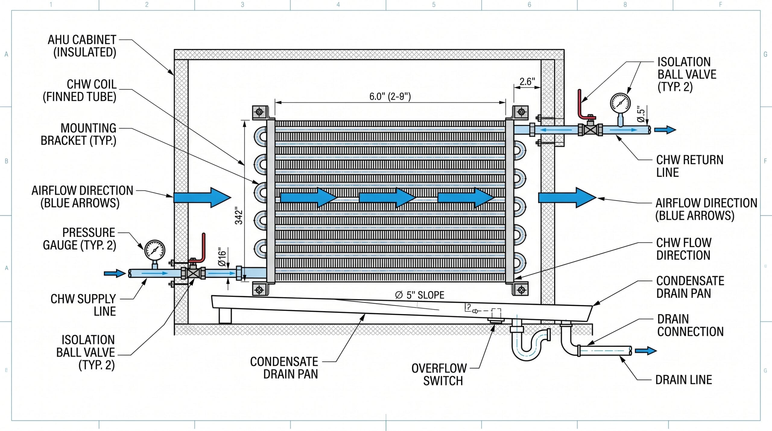
Large central air handling units are the primary home for chilled water coils. A typical AHU serves multiple rooms or an entire floor, moving 5,000–50,000 CFM through a coil bank. The coil might be 6–8 rows deep and 8 feet wide by 6 feet tall—massive compared to residential equipment. These installations often integrate economizers that use outdoor air for free cooling when conditions allow. When outdoor temperatures drop below 55°F, the economizer dampers open fully and the chilled water valve closes. The coil remains in place for humidity control and the occasional warm outdoor air day, but most cooling hours come from outside air. This is where proper coil selection matters—an oversized coil in an economizer application sees very low water flow for much of the year, which can cause control valve hunting and temperature swings. Integration with building automation systems lets the AHU modulate cooling capacity by throttling the chilled water control valve. As cooling load drops, the valve closes to reduce water flow through the coil. The leaving air temperature sensor feeds back to the controller, which adjusts the valve position to maintain setpoint. This is far simpler than staging multiple compressors in a DX system.
Fan Coil Units and VAV Systems
Zone-level temperature control uses smaller chilled water coils in fan coil units (FCUs) and variable air volume (VAV) boxes. An FCU is essentially a small blower, coil, and filter in a cabinet—often installed above a ceiling or under a window. Each unit serves a single room or small zone with its own thermostat. A four-pipe FCU system runs separate hot water and chilled water piping to each unit. The room thermostat calls for cooling, the chilled water valve opens, and the fan circulates room air across the cold coil. When heating is needed, the chilled water valve closes and the hot water valve opens to a separate heating coil. This gives precise zone control but requires double the piping infrastructure. VAV boxes with reheat coils solve a different problem. The central AHU delivers cold supply air (55°F) at variable volumes. When a zone needs less cooling, the VAV box damper closes to reduce airflow. But if the zone still needs some air movement for ventilation, that 55°F air would overcool the space. A small hot water reheat coil in the VAV box warms the air back up to maintain comfortable temperatures. Some VAV boxes use chilled water coils instead of electric reheat for zones with high cooling loads.
Specialized Industrial Applications
Process cooling demands precise temperature control that chilled water coils deliver reliably. Pharmaceutical manufacturing might require air at 68°F ±1°F and 45% RH ±3% for certain production areas. A properly selected chilled water coil with modulating control valve can hold those setpoints consistently—hour after hour, day after day. Cleanroom HVAC systems use chilled water coils extensively. ISO Class 5 and cleaner environments need 100% outside air with no recirculation (to prevent cross-contamination between rooms). That means cooling and dehumidifying massive volumes of outdoor air. A cleanroom serving a semiconductor fab might process 50,000 CFM through multiple parallel chilled water coil banks, each 12 feet wide by 8 feet tall. The coils must remove both sensible heat and the moisture load from humid outdoor air, then reheat the air to final supply temperature. Data center CRAC (computer room air conditioning) units increasingly use chilled water instead of DX refrigeration. A 20-ton CRAC unit with a chilled water coil is quieter, more efficient, and easier to maintain than a DX unit with a rooftop condenser. When server loads change rapidly, the chilled water valve responds within seconds—no compressor cycling, no refrigerant pressure transients, just smooth modulation.
How to Select the Right Chilled Water Coil
Select chilled water coils based on required cooling capacity (BTU/hr), available water flow rate (GPM), entering air conditions, and allowable pressure drop—typically sized using AHRI performance data. Getting this right the first time avoids the expensive mistake of replacing an undersized coil or wasting energy with an oversized one.
Critical Selection Parameters
Start with a proper cooling load calculation. You need both sensible heat (temperature change) and latent heat (moisture removal) for your space. Don’t use rules of thumb like “400 square feet per ton”—those are for quick feasibility checks, not actual equipment sizing. Use Manual N, HAP, or Trace software to calculate the actual load based on building envelope, occupancy, lighting, equipment, and ventilation requirements. Entering air conditions determine how hard the coil must work. Standard return air might be 75°F dry bulb and 62°F wet bulb (about 50% relative humidity). But if you’re conditioning 100% outdoor air in Miami during July, you’re looking at 92°F dry bulb and 79°F wet bulb—a much heavier load. The coil selection software requires both dry bulb and wet bulb temperatures to calculate total capacity. Water flow rate and temperature differential go hand in hand. Most systems design for 10°F ΔT—if your chiller supplies 44°F water, the coil returns 54°F water. The flow rate follows from the cooling load: GPM = (BTU/hr) / (500 × ΔT). For a 240,000 BTU/hr load with 10°F ΔT, you need 48 GPM. You can’t arbitrarily change these numbers—higher flow rates require larger pipes and pumps, while wider temperature differentials may not achieve adequate dehumidification. Air velocity affects both capacity and operating cost. Catalog ratings typically assume 400–500 FPM face velocity. Push beyond 550 FPM and pressure drop increases exponentially—you might gain 10% more cooling capacity but pay 40% more in fan energy forever. Worse, high velocities can pull water droplets off the condensate drain pan and send them into your ductwork. Keep face velocity at 450 FPM or below unless space constraints force a smaller coil. Allowable pressure drop is your budget for air-side resistance. A residential furnace blower might only overcome 0.5 inches of water column total external static pressure. A commercial AHU fan can handle 2–4 inches. Your coil’s pressure drop must fit within that budget alongside filters, ductwork, dampers, and diffusers. An 8-row coil at 450 FPM typically drops 0.5–0.7 inches. Add a dirty filter (another 0.8 inches) and long duct runs (0.6 inches) and you’ve consumed most of your available static pressure.
Performance Factors That Impact Efficiency
Fouling factors account for inevitable coil degradation over time. Clean copper tubes and aluminum fins transfer heat at rated capacity. After a year in service, a thin film of minerals deposits on the water side, and dust accumulates on the air side. Selection software applies fouling factors—typically 0.0001–0.0005 for the water side and 0.001 for the air side. These reduce effective heat transfer by 5–15%, so your coil must be sized with enough overhead to still meet capacity when fouled. Tube circuitry design affects how evenly water distributes across the coil face. A well-designed coil uses multiple parallel circuits (4–12 depending on size) so water velocity remains high enough for good heat transfer but not so high that friction losses become excessive. Poor circuitry can create dead spots where certain tubes barely participate in cooling—you’ve paid for that tube and fin area but aren’t getting much benefit from it. Fin spacing interacts with cleaning frequency in ways that impact long-term performance. That 14 FPI coil in a hospital might deliver 12% more capacity than a 10 FPI coil when both are clean. But if the 14 FPI coil needs cleaning every 6 months while the 10 FPI coil runs 18 months between cleanings, which one actually delivers more cooling over three years? Factor in the downtime cost for cleaning access and the maintenance labor, and the “less efficient” coil might be the better choice.
Common Selection Mistakes to Avoid
Undersizing for humidity control is surprisingly common. An engineer calculates sensible cooling load, picks a coil that meets that capacity, and ships the project. Then occupants complain about muggy conditions even though space temperature is correct. The problem? Dehumidification requires enough coil surface area below the dew point temperature. A 4-row coil might hit the sensible capacity target but lack the surface area to condense enough moisture. Use 6–8 rows minimum in humid climates, and verify that your selection software shows adequate latent capacity. Ignoring pressure drop impacts on fan energy is a gift that keeps on taking. You save $400 on first cost by specifying a cheaper 12-row coil instead of a larger-face-area 8-row coil. That 12-row coil has 0.9 inches of water column pressure drop while the 8-row option was 0.55 inches. The extra 0.35 inches means the fan must work harder—about 15% more energy in this case. Over 15 years, that’s thousands of dollars wasted for a one-time $400 savings. Specifying excessive rows chases diminishing returns. We’ve tested this repeatedly: going from 6 to 8 rows adds about 18% more capacity for 30% more cost and 45% more pressure drop. Going from 8 to 10 rows adds maybe 12% more capacity for another 25% cost increase and 35% more pressure drop. By the time you hit 12 rows, each additional row is contributing 5–8% more cooling while still adding its full share of cost and pressure drop. Run the selection at multiple row configurations—you’ll often find that a larger face area with fewer rows outperforms a smaller face with more rows.
| Parameter | Value | Notes |
|---|---|---|
| Cooling load | 240,000 BTU/hr | 20-ton requirement |
| Entering air | 78°F DB / 65°F WB | Standard return air |
| Leaving air | 55°F DB / 54°F WB | Supply air setpoint |
| Water flow | 48 GPM | 10°F ΔT (44°F to 54°F) |
| Face velocity | 450 FPM | Standard AHU |
| Recommended: | 6-row, 10 FPI | Balances efficiency & pressure drop |
Installation and Maintenance Best Practices
Proper installation requires correct water flow direction, adequate condensate drainage, air bleed provisions, and isolation valves; maintenance includes annual coil cleaning, water treatment monitoring, and leak inspections. These practices determine whether your coil lasts 8 years or 25.
Installation Requirements
Water piping orientation follows the natural flow pattern designed into the coil. Most coils are counterflow—water enters at the bottom on the leaving air side and exits at the top on the entering air side. This arrangement maximizes temperature differential and heat transfer efficiency. Installing a coil backwards reduces capacity by 8–12%. The coil datasheet shows the correct connection orientation—follow it. Manual air vents at the high points of the piping allow trapped air to escape during initial filling and after maintenance. Air pockets create noise (water hammer when bubbles collapse), reduce capacity (air doesn’t transfer heat like water does), and can cause flow distribution problems across parallel circuits. Install automatic air vents on the coil’s supply header and at any high points in the piping system. Check them weekly for the first month after startup, then monthly. Condensate pan sizing and drainage prevent the water damage we’ve cleaned up too many times. The pan must extend beyond the coil face on the leaving air side to catch all condensate. Size the drain connection for peak moisture removal—typically 1″ drain for coils up to 10 tons, 1.5″ for larger coils. Trap the drain properly with enough depth to overcome the negative pressure in the AHU cabinet, usually 2–3 times the fan static pressure in inches of water column. Access for cleaning deserves attention during installation, not years later when you can’t reach the coil. You need space to remove or at least tilt out the coil for inspection. Cabinet doors should provide clear access to both the entering and leaving air face. We’ve seen countless installations where someone specified a perfect coil but buried it in a mechanical room with 6 inches of clearance on all sides. Five years later when the coil needs cleaning, the only option is cutting ductwork.
Maintenance Schedule and Procedures
Coil cleaning frequency depends on your environment and filtration. In a clean office with MERV 11 filters and minimal outdoor air, annual cleaning suffices. We measure pressure drop across the coil at commissioning, then again at each maintenance visit. When measured pressure drop exceeds design by 20% or more, it’s time to clean regardless of the calendar. Water-side fouling from mineral deposits and biological growth reduces capacity gradually. If your building uses a cooling tower, the chilled water loop concentrates minerals as water evaporates. A proper water treatment program with corrosion inhibitors and biocides keeps this under control. Test water chemistry quarterly—pH should stay between 7.5–8.5, and total dissolved solids below the limits your treatment provider specifies. Freeze protection in cold climates is non-negotiable. We’ve replaced dozens of coils that split open from ice expansion. Three protection methods work: add propylene glycol to the water (10–20% for protection to 20°F), install low-temperature cutoff controls that shut down the AHU fan if supply water drops below 38°F, or use electric heat trace on exposed piping and drain the coil during extended cold weather. Never leave a coil full of plain water in a space that could see freezing temperatures.
Troubleshooting Common Chilled Water Coil Problems
The most common chilled water coil problems are insufficient cooling (caused by low water flow, air bypass, or fouling), water leaks (from freeze damage or corrosion), and high pressure drop (from dirty fins or excessive face velocity). Methodical diagnosis saves time and prevents replacing a coil that just needs cleaning.
Insufficient Cooling Capacity
When supply air temperature runs warmer than setpoint despite the control valve being fully open, check water flow first. Install a temporary ultrasonic flow meter on the supply pipe while the system runs at peak load. Compare measured GPM against design. If actual flow is 20% or more below design, you’ve found the problem—strainer clogging, a partially closed isolation valve, or pump issues. Air bypass around the coil shows up as inconsistent supply air temperature across the duct or AHU leaving section. Pull a few downstream filters and use a thermal imaging camera or infrared thermometer to scan the duct cross-section. Temperature variations exceeding 3–4°F indicate air is sneaking around the coil rather than passing through it. Check the coil casing for gaps where it meets the AHU cabinet, and inspect the gasket seals. Fouled coil surfaces look obvious once you open the access door—the fins are packed with dust on the entering air side or covered with a whitish mineral film on the leaving air side. Less obvious is water-side fouling. If the air side looks clean but capacity is still down, and water flow is correct, suspect scale buildup inside the tubes. This requires chemical cleaning or coil replacement if the buildup is severe.
Leaks and Pressure Loss
Freeze damage leaves unmistakable evidence—split tubes that often bulge outward where ice expansion burst them. The failure typically happens across multiple tubes in the same area, wherever water froze first (usually near the entering water header in the coldest part of the coil). Small pin-hole leaks from corrosion show up as white or green mineral deposits on the exterior tube surface where water seeps out and evaporates. Water chemistry problems cause accelerated corrosion. If your water pH drops below 7.0 or chloride content exceeds 200 ppm, copper tubes corrode from the inside. This often goes unnoticed until a tube suddenly fails. The solution is fixing your water treatment program before replacing the coil, or the replacement will fail just as fast. Testing a suspected leak requires isolating the coil and pressurizing it with dry nitrogen to 150 PSIG (or 1.5 times operating pressure, whichever is greater). Submerge the coil underwater if possible, or apply soapy water to all joints and tube surfaces. Tiny bubbles show leak locations. Small leaks in headers can sometimes be repaired by brazing; tube leaks usually mean coil replacement because accessing tubes buried inside the fin pack is impractical.
Pricing and Cost Considerations
Standard chilled water coils cost $800–$3,500 depending on size, with 6-row coils for typical AHUs ranging $1,200–$2,000; factors affecting price include row depth, fin material, AHRI certification, and custom features. Understanding the total cost picture helps you make intelligent trade-offs between first cost and lifecycle expense.
Cost Breakdown by Configuration
Size drives base pricing—a 24″ × 24″ coil costs far less per square foot of face area than a 60″ × 60″ coil due to economies of scale in manufacturing. But don’t undersize to save money; the fan energy penalty for a smaller, deeper coil will cost more than the initial savings within 2–3 years. Row depth adds cost linearly up to about 8 rows, then the incremental cost per row increases. Going from 6 to 8 rows might add 25% to coil price, while going from 8 to 10 rows adds another 30%. This is partly due to heavier casing required to support the added weight, and partly because fewer manufacturers stock very deep coils—you’re often buying a custom configuration. Material upgrades carry significant premiums. Copper fins instead of aluminum add 40–60% to coil cost but provide better corrosion resistance in coastal or industrial environments. Stainless steel headers (instead of copper) for harsh water chemistry add 30–50%. Epoxy-coated fins for maximum corrosion protection can double the coil price, but in a wastewater treatment plant or chemical processing facility, it’s cheaper than replacing corroded coils every 5 years. AHRI certification costs the manufacturer several thousand dollars per coil model for testing and annual fees. They pass some of that cost along—AHRI-certified coils typically cost 8–12% more than non-certified equivalents. You’re paying for performance verification and the assurance that published ratings are accurate.
Total Ownership Cost Analysis
Energy efficiency impacts operating cost far more than first cost in most applications. Consider two coils for the same application: Coil A costs $1,800 with 0.55 inches of water column pressure drop, while Coil B costs $1,400 with 0.75 inches of pressure drop. That extra 0.20 inches costs about $180 per year in fan energy (assuming $0.12/kWh electricity and 4,000 operating hours). Over a 15-year service life, Coil A saves $2,700 minus its $400 higher first cost—a $2,300 net advantage. Maintenance costs include scheduled cleaning plus unplanned repairs. Budget $200–400 per cleaning event for labor and materials on a typical AHU coil. In clean environments with annual cleaning, that’s $3,000–6,000 over 15 years. In dusty environments requiring quarterly cleaning, you’re spending $12,000–24,000. This is why proper filtration and realistic fin spacing selection matters—the “high-efficiency” 14 FPI coil might cost you $10,000 more in cleaning over its life compared to a 10 FPI coil that costs $300 less up front. Replacement frequency depends on installation quality and maintenance. A properly installed coil with good water treatment should last 18–25 years. Poor installation or neglected maintenance cuts that to 8–12 years. At $2,000 per replacement plus installation labor, premature failure due to frozen tubes or corrosion adds thousands to your lifecycle cost.
| Coil Size | Rows | Approx Cost | Application |
|---|---|---|---|
| 24″ × 24″ | 4 | $800–$1,200 | Small FCU |
| 36″ × 36″ | 6 | $1,500–$2,200 | Standard AHU |
| 48″ × 48″ | 8 | $2,500–$3,800 | Large AHU |
| 60″ × 60″ | 10 | $4,000–$6,500 | Industrial/data center |
Future Trends in Chilled Water Coil Technology (2026 & Beyond)
Emerging chilled water coil innovations for 2026+ include microchannel designs for 15–20% higher efficiency, antimicrobial coatings to reduce biofilm fouling, and smart coils with embedded sensors for predictive maintenance. These technologies address the industry’s push toward lower energy consumption and reduced maintenance burden.
Advanced Materials and Coatings
Microchannel tube technology migrated from automotive and DX refrigeration coils into chilled water applications starting around 2024. Instead of 0.5″ round copper tubes, microchannel coils use aluminum flat tubes with multiple small parallel channels. This increases internal surface area dramatically while reducing water volume by 60–70%. Early field tests show 15–20% higher heat transfer efficiency in the same face area, or equivalent capacity in 30% less depth. The catch? Cost runs 80–120% higher than conventional coils, and repair is impossible—microchannels can’t be pressure-tested and patched like copper tubes. Hydrophobic fin coatings cause condensate to bead up and run off rather than forming a water film that blocks airflow. This maintains lower pressure drop as the coil operates in wet conditions. Field measurements from hospital installations show 8–12% lower average pressure drop during cooling season compared to uncoated coils. The coating adds $150–300 to a typical AHU coil but can pay back in 3–5 years through reduced fan energy. Antimicrobial coatings using silver ion technology prevent bacterial and fungal growth on the fin surfaces. This matters most in healthcare facilities where biofilm on cooling coils can become a source of hospital-acquired infections. The coating doesn’t eliminate the need for cleaning but extends the interval between cleanings by 40–60%. Early adoption remains concentrated in hospitals, but expect broader use as building codes increasingly focus on indoor air quality.
Smart Monitoring and Controls
Embedded sensors transform chilled water coils from passive heat exchangers into smart equipment that reports their own condition. Wireless temperature sensors on the entering and leaving air and water sides provide real-time data on coil performance. When the measured capacity drops below expected values (calculated from airflow, water flow, and temperature differential), the building management system alerts maintenance staff before occupant complaints start. Pressure sensors on both air and water sides detect fouling early. A gradual increase in air-side pressure drop indicates the coil needs cleaning. A sudden change in water-side pressure drop might indicate a strainer blockage or control valve failure. These sensors cost $200–400 per coil to install but reduce unplanned downtime by catching problems during early stages when fixes are simple. Variable water flow optimization uses these sensors to minimize pumping energy without sacrificing comfort. Traditional chilled water systems run pumps at constant speed or use basic two-position control valves at each coil. Smart systems modulate both pump speed and individual coil valve positions based on real-time load data from temperature and pressure sensors. Buildings with this technology report 20–30% reductions in chilled water pumping energy compared to constant-volume systems.
| Technology | Efficiency Gain | Adoption Timeline | Key Benefit |
|---|---|---|---|
| Microchannel tubes | 15–20% | 2026–2028 | Reduced refrigerant/water volume |
| Antimicrobial coating | 5–10% | Available now | Lower fouling, cleaning frequency |
| IoT sensor integration | 10–15% | 2027–2030 | Predictive maintenance, optimal control |
FAQ
Q: What is a chilled water coil? A: A chilled water coil is a heat exchanger that cools air by circulating cold water through finned copper tubes. The coil is installed in HVAC equipment like air handling units, where warm air passes over the cold fins and tubes, transferring heat to the water. The warmed water returns to a central chiller to be cooled again. This differs from refrigerant-based systems where cooling happens directly at the coil. Q: What is the difference between a chilled water coil and a DX coil? A: A chilled water coil circulates cold water as the cooling medium, while a DX (direct expansion) coil uses refrigerant that evaporates inside the coil tubes. Chilled water systems require a separate chiller plant with pumps and piping but offer better efficiency for large buildings with multiple zones. DX systems are self-contained and simpler but less efficient for buildings over 50,000 square feet. Chilled water also provides more precise temperature control (±2°F vs ±4°F for DX). Q: What is a chiller coil? A: “Chiller coil” is another term for chilled water coil—the coil that receives cold water from a chiller. Some people use “chiller coil” to distinguish it from heating hot water coils (which use the same construction but carry hot water instead). Both terms refer to the same finned-tube heat exchanger used for air cooling in HVAC systems. Q: What is a chilled water coil for refrigeration? A: In refrigeration contexts, chilled water coils are used for process cooling or temperature control in cold storage facilities. For example, a brewery might use chilled water coils to cool fermentation tanks, or a food processing plant might use them in controlled-temperature rooms. The coil construction is identical to HVAC coils, but the water temperature may be lower (35–40°F) and the application focuses on maintaining product temperature rather than comfort cooling. Q: How many rows should a chilled water coil have? A: Most commercial HVAC applications use 6–8 row coils, which balance cooling capacity and pressure drop. Use 3–4 rows only for light-duty applications with low humidity. Specify 10–12 rows when you need deep dehumidification or very cold supply air (below 52°F). Adding rows beyond 8 gives diminishing returns—each additional row adds less capacity but still increases pressure drop and cost. Q: How often do chilled water coils need cleaning? A: In clean office environments, clean coils annually. In hospitals or labs with high filtration, you can extend to 18–24 months. Industrial facilities with dust or outdoor air economizers may need cleaning every 3–6 months. You’ll know cleaning is overdue when supply air temperature rises despite proper water flow, or when measured air pressure drop across the coil exceeds design by 20% or more. Q: Can a chilled water coil freeze and burst? A: Yes—if water remains in the coil during freezing conditions without flow or heat, ice expansion will split the copper tubes. This is the most common cause of catastrophic coil failure. Prevent it with glycol in the water loop (10–20% propylene glycol for freeze protection to 20°F), low-temperature cutoff controls that shut down fans if water drops below 38°F, or electric heat trace on the coil and piping in exposed locations. Q: What water temperature should I use for a chilled water coil? A: Standard chilled water systems supply 42–44°F water to the coil and return 52–56°F water to the chiller (10–14°F temperature rise). This range provides efficient dehumidification while avoiding freeze risk. Lower supply temperatures (38–40°F) are used for laboratories or high-latent-load applications but require special freeze protection. Higher temperatures (48–50°F) reduce dehumidification and are only suitable for sensible cooling in dry climates.
Choosing the Right Chilled Water Coil for Your System
Selecting the right chilled water coil comes down to matching five parameters: your cooling load, available water flow, air-side pressure budget, space constraints, and maintenance access. Start with a proper cooling load calculation—don’t guess or copy another building’s design. Undersized coils run at full capacity year-round with no safety margin, while oversized coils waste upfront cost and may have control problems at low loads. Work with your chiller plant capacity. If you only have 40 GPM available, don’t specify a coil that needs 60 GPM to meet rated capacity. Check the air velocity—face velocities above 500 FPM start pulling condensate off the drain pan, and velocities above 600 FPM dramatically increase pressure drop and noise. For coils in occupied spaces, keep face velocity at 400–450 FPM. Don’t over-specify rows. We’ve tested countless installations where engineers specified 8-row coils when 6 rows would have done the job at 25% lower cost and 15% less fan energy. The last two rows add maybe 10% more capacity while doubling the pressure drop. Run the selection software at multiple row configurations and compare total cost—coil price plus 15 years of fan energy. Finally, plan for maintenance from day one. If you can’t pull the coil out for cleaning or access both sides for inspection, you’re setting up a problem three years from now when performance drops and no one can fix it without cutting ductwork.