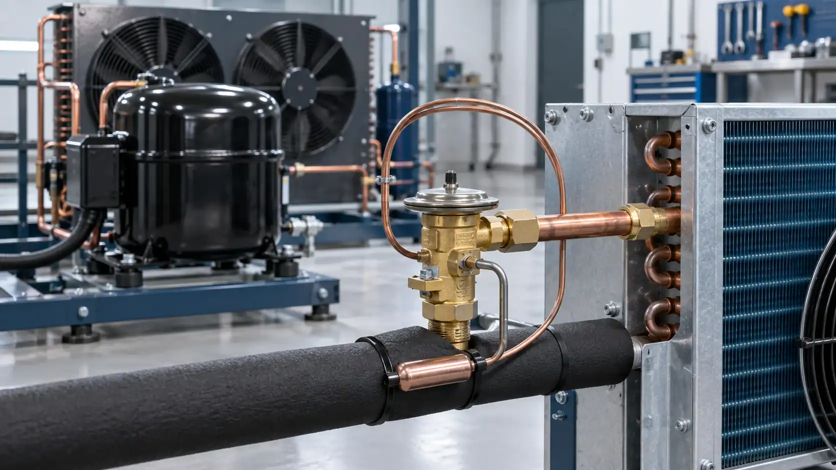
A thermostatic expansion valve (TXV) meters liquid refrigerant into a direct-expansion evaporator by responding to evaporator outlet superheat. The valve balances sensing-bulb pressure, evaporator pressure, and spring force so the evaporator receives enough refrigerant for the current load while vapor leaves the outlet before it reaches the compressor. A correct TXV selection requires more than pipe size: confirm refrigerant, capacity, evaporating temperature, condensing condition, pressure drop, equalizer method, distributor arrangement, bulb charge, connection type, and the commissioning superheat target.
This guide is written for refrigeration engineers, OEM buyers, contractors, distributors, and project teams comparing a new valve or a replacement. It separates the working principle from the selection and installation decisions that determine whether the valve will control steadily in the finished system.
What a thermostatic expansion valve does
A TXV is a throttling and metering device between the liquid line and the evaporator. It creates a pressure drop, lowers the refrigerant saturation temperature, and regulates mass flow into the evaporator. The valve reacts to the condition at the evaporator outlet rather than simply opening by a fixed percentage.
| Buyer question | Practical TXV answer | Why it matters in an RFQ |
|---|---|---|
| What does it control? | Refrigerant mass flow into a direct-expansion evaporator | The valve must match load, refrigerant, and operating temperatures |
| What signal does it use? | Outlet temperature and evaporator pressure, expressed as superheat | The sensing bulb and equalizer location must be defined |
| What does it protect against? | Liquid floodback when applied and adjusted correctly | Poor bulb contact, wrong charge, or overfeeding can still damage a compressor |
| Is it fixed or modulating? | It modulates the opening as load and superheat change | Capacity and pressure-drop data are needed for stable control |
| Where is it installed? | In the liquid feed near the evaporator inlet | Distributor layout and service access affect the installation |
The word “thermostatic” refers to the temperature-responsive element, not to a room thermostat. A TXV does not directly set room temperature, compressor staging, or defrost timing. Those functions belong to the wider refrigeration control system. For that boundary, see the refrigeration controls guide.
How a thermostatic expansion valve works
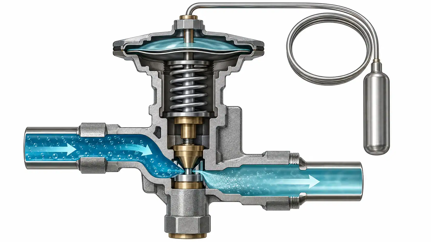
The valve has a power element, sensing bulb, capillary tube, diaphragm, spring, valve seat, orifice, and an equalizer passage or connection. At a steady condition, three main forces balance:
| Force | Source | Direction on the diaphragm | Operating effect |
|---|---|---|---|
| Bulb pressure | Fluid in the sensing bulb responds to suction-line temperature | Opens the valve | Higher sensed temperature generally increases opening force |
| Evaporator pressure | Pressure transmitted through an internal or external equalizer | Closes the valve | Changes with evaporating pressure and pressure drop through the evaporator |
| Spring pressure | Superheat adjustment spring | Closes the valve | Establishes the static portion of the superheat setting |
The simplified balance is bulb pressure = evaporator pressure + spring force. When load rises, the evaporator outlet tends to become warmer and the bulb pressure rises. The diaphragm moves toward opening, admitting more liquid. When the outlet cools and superheat falls, the closing forces regain the balance and the valve reduces flow.
This response is why a TXV can follow changing load more effectively than a fixed restrictor. It does not mean the valve can correct every system problem. A starved liquid line, blocked filter-drier, inadequate subcooling, wrong refrigerant charge, poor airflow, or an incorrectly installed bulb can all appear as a metering problem.
The ASHRAE refrigeration control device chapter describes the same pressure balance and distinguishes static, opening, and operating superheat. The Danfoss TXV explanation is also useful when training installation and service teams.
Superheat: the control variable buyers must define
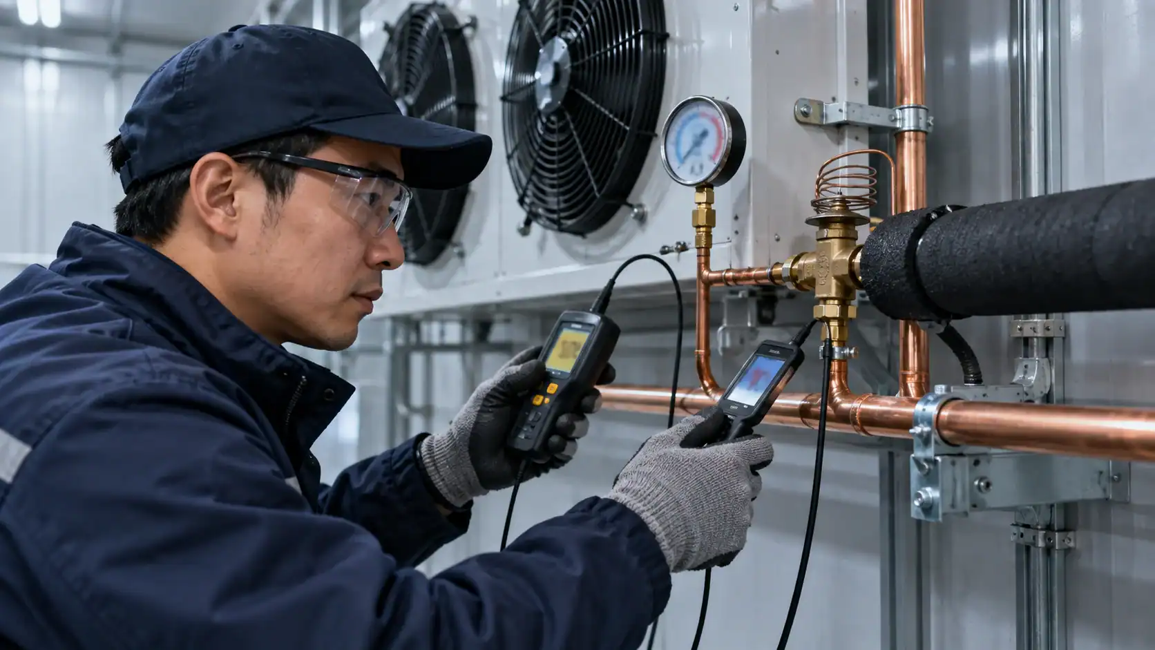
Superheat is the difference between the actual vapor temperature at a measurement point and the refrigerant saturation temperature corresponding to the measured pressure at that point. At a TXV system, technicians normally evaluate evaporator outlet superheat or total suction superheat according to the equipment design and the manufacturer’s procedure.
| Term | Meaning | Use during selection or commissioning |
|---|---|---|
| Static superheat | Superheat at which the valve begins to open | Part of the factory setting and spring selection |
| Opening superheat | Additional superheat needed to open the valve to a useful position | Used in manufacturer capacity ratings |
| Operating superheat | Static plus opening superheat at the working load | The field value used to assess feed and floodback risk |
| Evaporator outlet superheat | Temperature rise above saturation at the evaporator outlet | Helps confirm that the evaporator is fed without returning liquid |
| Total suction superheat | Outlet superheat plus heat picked up in the suction line | Useful for compressor inlet protection, but do not confuse it with evaporator outlet superheat |
The exact target depends on refrigerant, evaporator design, load, distributor, compressor requirements, and the equipment maker’s instructions. Avoid putting a universal number into an RFQ when the system conditions are not known. A valve selected on “maximum reserve capacity” can run at an undesirable superheat and may modulate poorly at low load.
Sensing bulb and equalizer arrangement
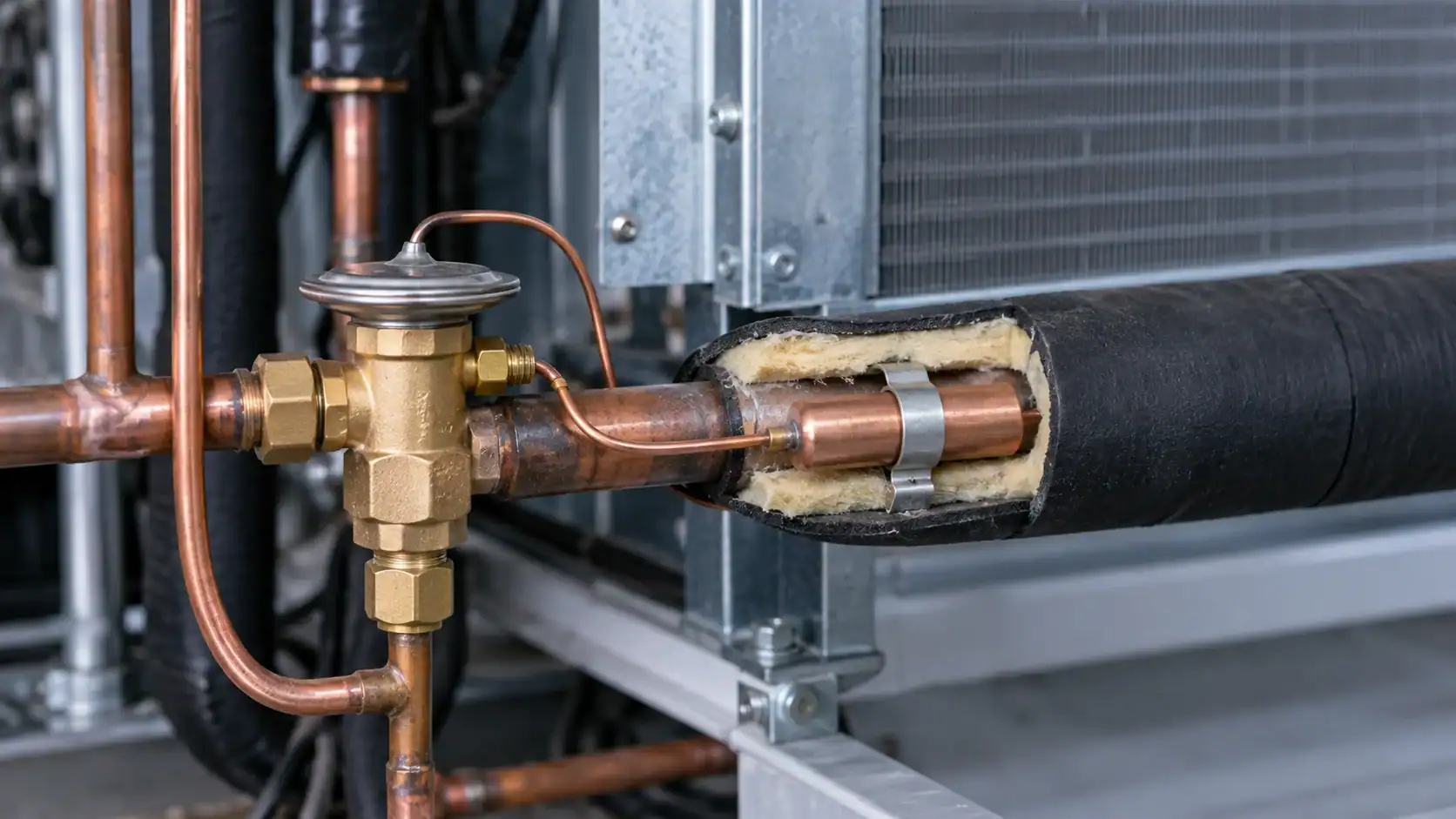
The sensing bulb is the valve’s temperature input. It normally sits on the suction line at the evaporator outlet, where it can sense representative vapor temperature. The line must be clean, the bulb must make firm thermal contact, and the clamp must suit the tube size. Insulation may be needed when surrounding air could distort the reading.
The bulb location is part of the control design. If it is too close to a heat source, placed where liquid can collect, mounted on a poorly representative section, or left loose, the TXV may hunt, underfeed, or overfeed. The installer should follow the valve manufacturer’s permitted orientation and bulb position for the actual pipe diameter and refrigerant.
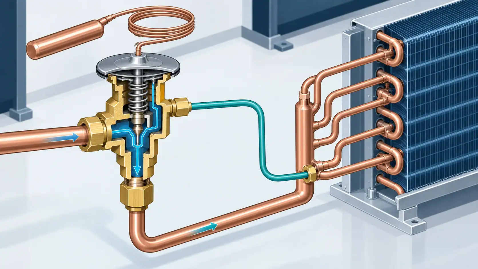
Internal equalization takes evaporator pressure through a passage in the valve body. External equalization uses a separate line connected to the evaporator outlet or another specified pressure point. External equalization is often required when the evaporator, distributor, or suction path creates a meaningful pressure drop. The selection should be confirmed against the evaporator circuit design instead of inferred from connection size.
| Arrangement | Appropriate starting point | Questions to confirm |
|---|---|---|
| Internal equalizer | Compact single-circuit evaporator with limited internal pressure drop | Is the pressure at the valve outlet representative of the evaporator outlet? |
| External equalizer | Multi-circuit evaporator, distributor, or higher pressure drop | Where should the equalizer connect, and is a pressure tap or fitting included? |
| External equalizer with distributor | Systems where distribution pressure loss affects the control point | Does the selected valve capacity account for distributor pressure drop? |
| Remote or unusual bulb location | Equipment with special suction routing or heat exchangers | Does the manufacturer approve the sensing point and charge for this arrangement? |
TXV types and when to compare them
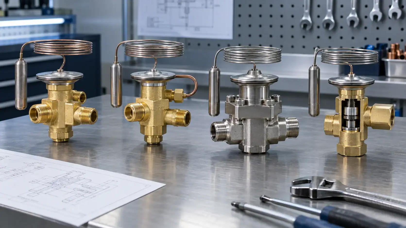
Different TXVs can look similar while having different control behavior. Compare the internal construction and application rating, not only the inlet and outlet connection.
| TXV type or feature | What changes | Where it can be useful |
|---|---|---|
| Internally equalized | Evaporator pressure is sensed through the valve body | Simple circuits with small pressure drop |
| Externally equalized | A dedicated equalizer senses pressure at the specified downstream point | Multi-circuit evaporators and distributor applications |
| Conventional port | Port forces vary with pressure conditions in the valve | Smaller or less demanding applications when the manufacturer rating permits |
| Balanced port | Port design reduces the effect of inlet pressure variation on opening force | Larger capacity or changing head-pressure conditions when specified |
| Universal bulb charge | Broad operating response across a defined temperature range | General applications within the charge manufacturer’s envelope |
| Anti-hunt or selective charge | Damping or a selected pressure-temperature response changes modulation | Systems where hunting or a narrow operating range is a concern |
| Interchangeable orifice | The body and metering capacity can be matched with an insert | Service inventory and selected capacity ranges, if approved by the manufacturer |
The Danfoss walk-in cooler explanation explains how the bulb, diaphragm, equalizer, and spring work together. For a serviceable commercial or industrial design, also record whether the power element, body, orifice, and connections are replaceable as separate parts.
TXV selection inputs for a refrigeration project

A manufacturer or distributor should be able to reproduce the selection from the information in the RFQ. Provide operating points rather than only nominal horsepower or pipe diameter.
| Selection input | Minimum information to provide | Why the valve supplier needs it |
|---|---|---|
| Refrigerant | Exact refrigerant designation and blend or retrofit status | Capacity, pressure-temperature behavior, bulb charge, and materials depend on it |
| Refrigeration capacity | Required capacity at the design evaporating condition | The valve must feed the load without relying on unapproved reserve capacity |
| Evaporating temperature | Design and expected operating range | Determines pressure, superheat behavior, and valve rating |
| Condensing condition | Design condensing temperature or pressure range | Affects available pressure drop and liquid feed stability |
| Liquid temperature and subcooling | Temperature at the valve inlet and available liquid subcooling | Confirms that liquid reaches the metering device without flash gas |
| Pressure drop | Available pressure drop across the valve at the design point | Capacity tables are tied to pressure drop, not connection diameter alone |
| Evaporator circuit | Single or multi-circuit, distributor type, and pressure loss | Determines equalizer arrangement and distributor compatibility |
| Bulb charge and superheat | Required charge family and initial or factory setting | Controls the response range and low-load behavior |
| Connections | Inlet/outlet size, tube material, flare/braze or other connection | Prevents a dimensional match from hiding a flow or installation mismatch |
| Ambient and duty | Room, process, pull-down, holding load, and turndown range | Reveals whether the valve must modulate across a wide load range |
Do not size a TXV from compressor displacement alone. The valve sees evaporator load and pressure conditions. If the equipment operates in several modes, list each mode and ask the supplier to check the selected orifice and capacity across the operating envelope.
Matching TXV capacity to pressure drop and load
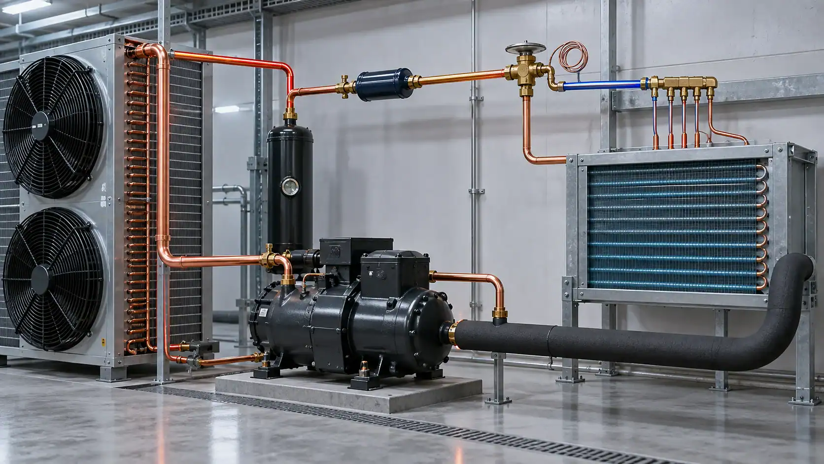
Capacity tables usually vary by refrigerant, evaporating temperature, condensing or inlet condition, and pressure drop. A valve that appears large enough at one operating point may be unstable at another. A valve that is too small can starve the evaporator at peak load; a valve that is too large can lose resolution and hunt at part load.
Use this sequence when comparing catalog selections:
- State the design capacity and the capacity range, including pull-down and minimum holding load.
- Determine the liquid temperature and pressure available at the valve inlet.
- Calculate or obtain the available pressure drop across the valve after accounting for line, solenoid, distributor, and fitting losses.
- Use the manufacturer’s capacity table or selection tool for the exact refrigerant and evaporating condition.
- Check the selected valve at the low and high operating points, including turndown.
- Confirm that the valve, orifice, charge, equalizer, and distributor are a matched assembly.
The Parker Sporlan Virtual Engineer selection tool illustrates why selection requires application data. Treat any catalog result as a starting selection until the supplier confirms the final operating envelope.
Refrigerant, bulb charge, and material compatibility
The refrigerant affects pressure-temperature behavior, capacity, required materials, and the response of the thermostatic element. A replacement valve must be checked against the actual refrigerant in the circuit, including a retrofit or blend change. “Same connection” is not proof of compatibility.
Confirm these items in the technical submittal:
- Refrigerant designation and whether the system has been converted from another refrigerant.
- Approved bulb charge or power element for the evaporating temperature range.
- Valve body, seat, diaphragm, seals, and gasket compatibility.
- Pressure rating and allowable working pressure for the high and low sides.
- Oil and contamination conditions, especially after a compressor failure or burnout.
- Whether the valve needs a filter-drier, inlet strainer, or clean-up procedure upstream.
The Danfoss fitter notes describe the pressure balance and the role of the spring in setting superheat. For final selection, the valve manufacturer’s current catalog and application data control.
Common TXV symptoms and diagnostic order
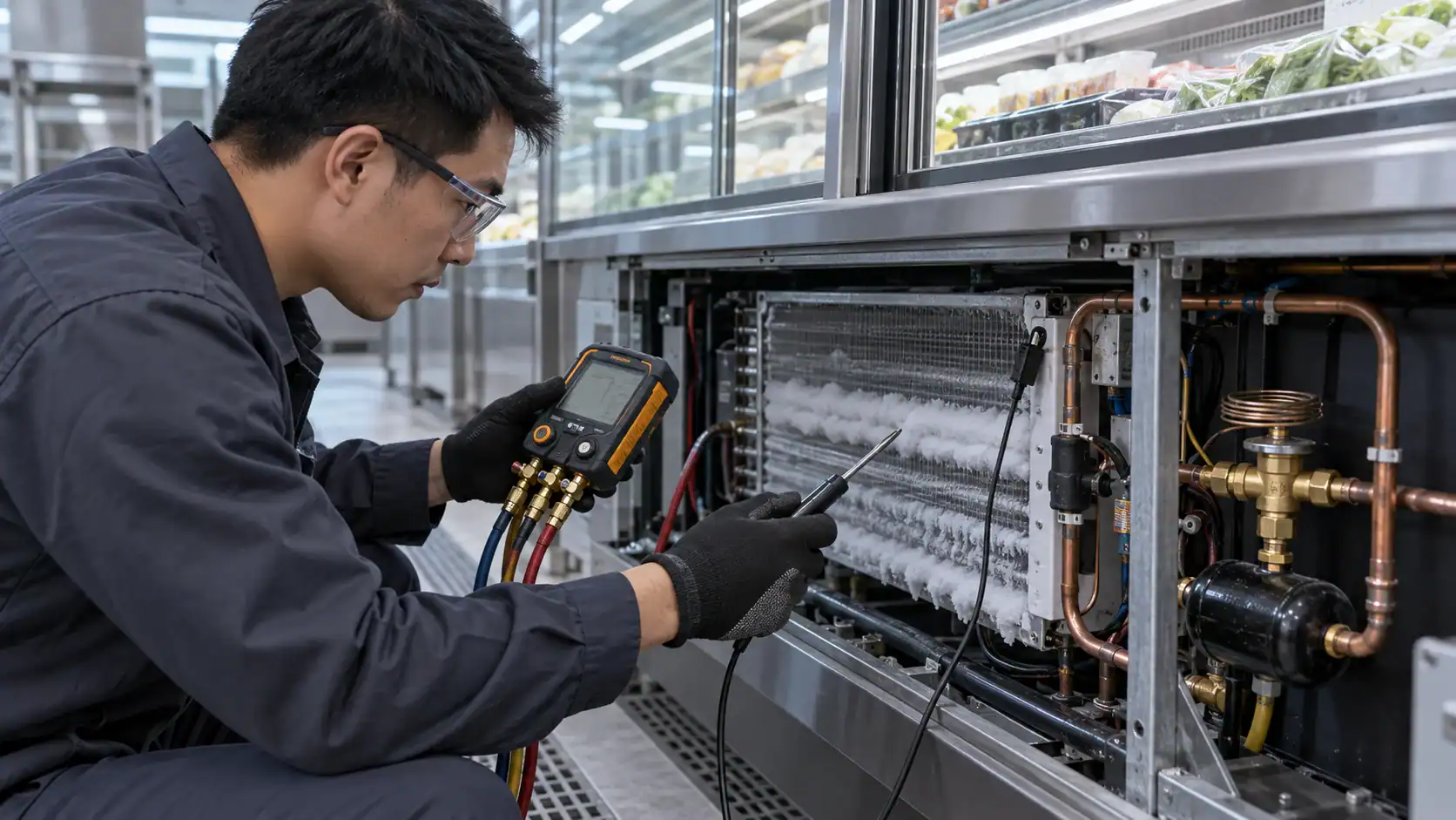
A system symptom rarely proves that the TXV itself is defective. Use a fixed diagnostic order so a blocked liquid line or incorrect charge is not mistaken for a bad valve.
| Observed symptom | Possible TXV or system causes | Checks before replacement |
|---|---|---|
| Low evaporator capacity and high outlet superheat | Starved valve, low liquid pressure, flash gas, blocked drier, low charge, bulb not sensing | Check liquid subcooling, sight glass where fitted, pressure drop, bulb contact, and equalizer |
| Low superheat or floodback risk | Overfeeding, wrong bulb charge, loose bulb, incorrect adjustment, low load, distributor problem | Verify measurement point, bulb installation, load, refrigerant charge, and compressor protection |
| Hunting superheat | Oversized valve, unstable pressure drop, poor bulb location, incompatible charge, intermittent liquid feed | Record superheat over time and inspect inlet condition and load changes |
| Frost at the valve or inlet | Pressure drop and flashing, moisture, restriction, or abnormal low-side condition | Check filter-drier, liquid temperature, pressure readings, and refrigerant state |
| No response to adjustment | Damaged power element, seized needle, blocked equalizer, wrong adjustment direction, or a different system fault | Follow the manufacturer procedure and verify pressure and temperature instruments |
| Works at one load but fails at another | Capacity, charge, or pressure-drop mismatch across the operating range | Recheck low-load and peak-load selection points |
Do not turn the adjustment stem repeatedly without recording the original position and waiting for the system to stabilize. A pressure-temperature reading taken at one instant can hide a hunting or intermittent condition. If a compressor has experienced floodback or burnout, include oil and system cleanliness checks in the service plan.
Installation details that affect TXV performance
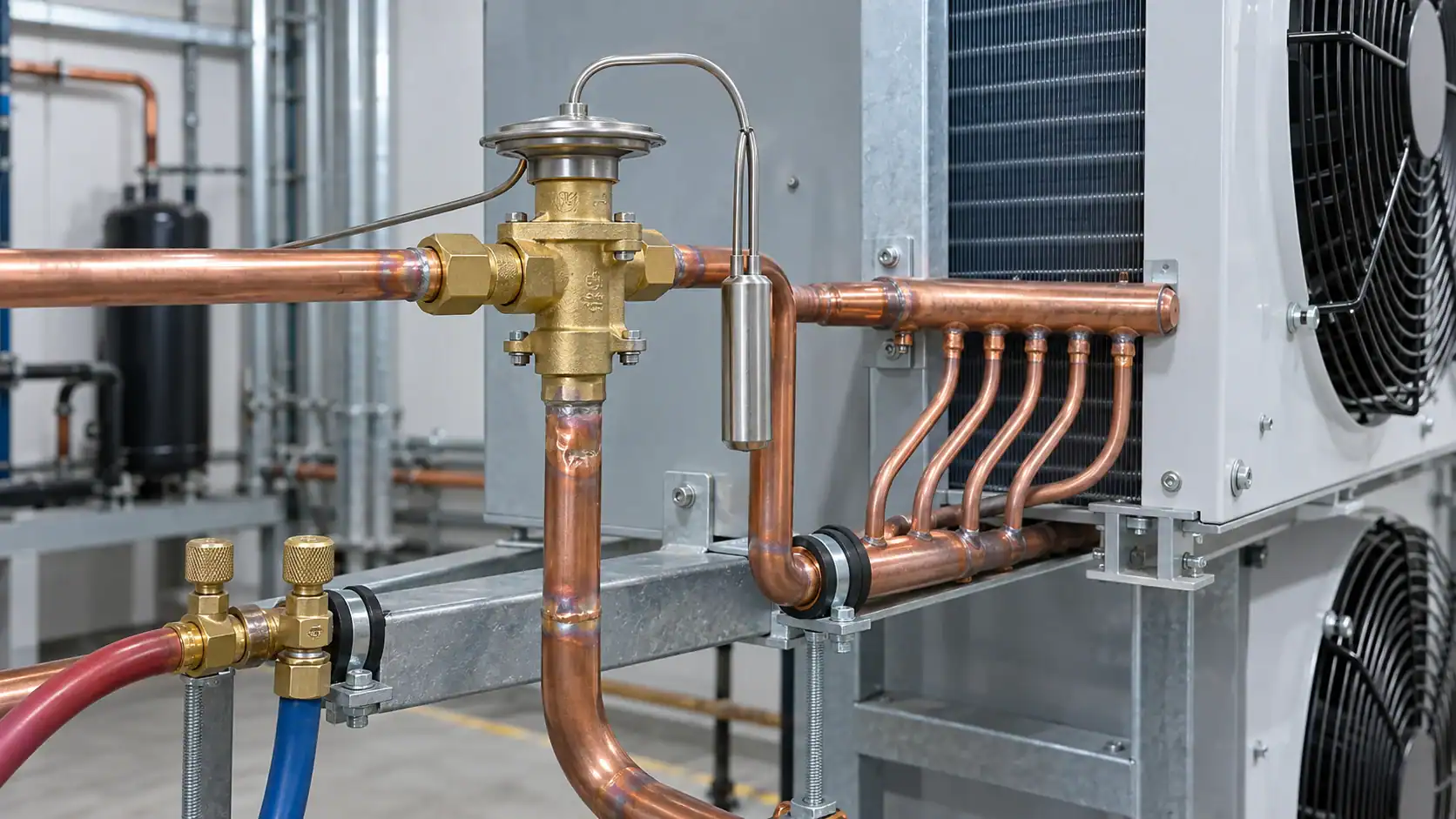
Follow the valve manufacturer’s installation bulletin and the equipment drawing. The Sporlan installation bulletin emphasizes valve location, distributor proximity, support, and correct equalizer and bulb installation.
Installation checks should include:
- Mount the valve as close to the evaporator as the circuit design permits.
- Keep the line between valve and distributor short and free from unnecessary elbows or restrictions.
- Protect the valve body and power element from excessive brazing heat.
- Install the bulb on a clean, representative suction-line surface with the specified clamp and orientation.
- Secure and insulate the bulb where the manufacturer or equipment design requires it.
- Route the external equalizer to the specified pressure point, with no unintended restriction or trapped oil pocket.
- Support larger valves and tubing so vibration does not load the joints.
- Keep moisture, debris, brazing scale, and open-air exposure out of the circuit.
If a solenoid valve, hand valve, distributor, suction accumulator, or heat exchanger is placed around the TXV, show it on the piping diagram and include its pressure drop in the selection review.
Commissioning and superheat verification
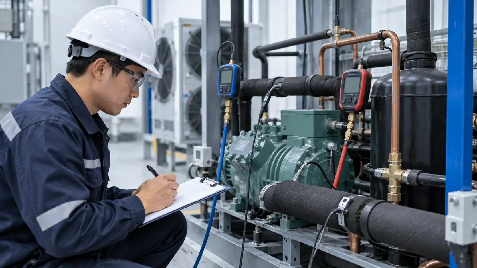
Commissioning should establish a stable baseline before the TXV is adjusted. Record the refrigerant, outdoor or plant condition, room or process load, evaporator and suction pressures, relevant temperatures, liquid-line condition, compressor status, and defrost state.
| Commissioning step | Record | Decision |
|---|---|---|
| Confirm the circuit | Refrigerant, valve model, orifice, bulb charge, equalizer, and piping orientation | Reject a mismatch before adjustment |
| Confirm liquid feed | Liquid temperature, subcooling, pressure at valve inlet, and filter-drier condition | Correct flash gas or restriction first |
| Measure evaporator outlet | Pressure and temperature at the specified measurement point | Calculate the intended superheat value |
| Observe stability | Readings across pull-down, holding, and minimum load | Identify hunting or poor turndown |
| Check compressor inlet | Suction temperature, pressure, and manufacturer limits | Confirm that the compressor is protected |
| Adjust only if required | Direction, amount, time allowed for stabilization, and final readings | Preserve a traceable final setting |
Superheat measurement requires a pressure reading converted with the correct refrigerant pressure-temperature relationship and a temperature measurement at the correct pipe location. Do not compare a suction-line temperature several meters from the evaporator with an evaporator outlet target without accounting for line heat gain.
What to include in a TXV RFQ
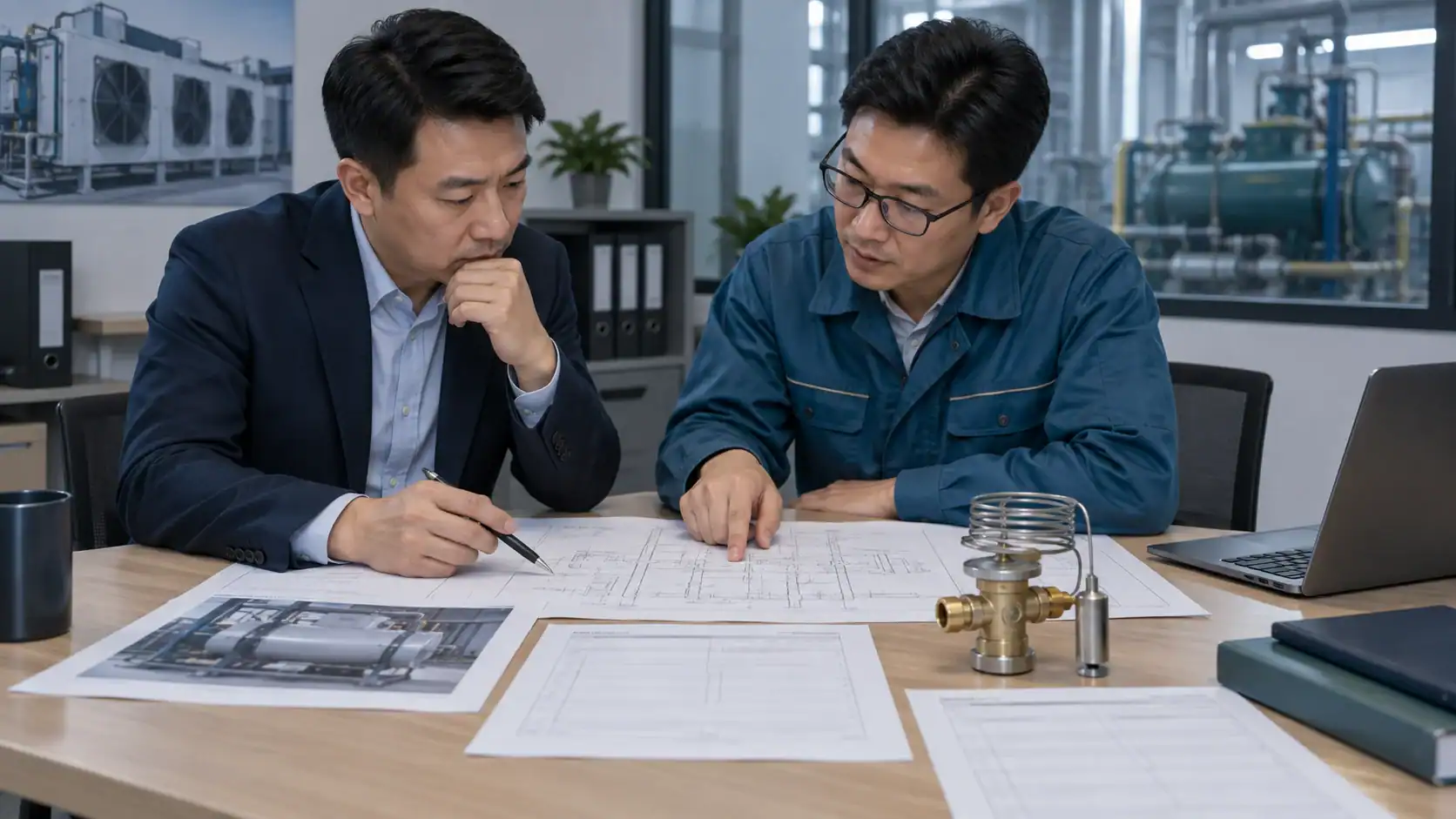
A strong RFQ lets suppliers compare equivalent valves and exposes missing engineering inputs early. Attach the P&ID or piping sketch and mark the measurement points.
| RFQ field | Example of a useful entry |
|---|---|
| Application | Medium-temperature cold room, low-temperature freezer, process cooler, or heat-pump circuit |
| Refrigerant | Exact designation, blend or retrofit note, and oil type if relevant |
| Capacity | Design capacity with units and required operating range |
| Evaporating condition | Design evaporating temperature and expected range |
| Condensing condition | Design condensing temperature or pressure and ambient range |
| Liquid condition | Liquid temperature, subcooling, and pressure at TXV inlet |
| Valve pressure drop | Available pressure drop after upstream and downstream losses |
| Evaporator circuit | Circuit count, distributor, circuit pressure drop, and external equalizer need |
| Valve construction | Body material, balanced or conventional port, replaceable orifice, and service parts |
| Connections | Inlet/outlet size, connection style, orientation, and tube material |
| Documentation | Capacity table, compatibility statement, installation instructions, spare parts, and test records |
Ask for the supplier’s selected model, orifice, charge, equalizer arrangement, rated capacity at your conditions, and any minimum or maximum operating limits. “TXV, 7/8 inch” is not a complete purchasing specification.
Quality and incoming inspection checklist
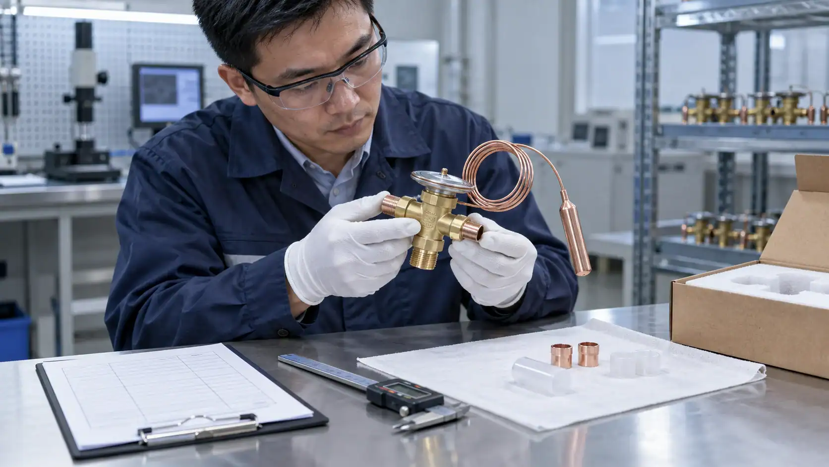
Before installation, inspect the delivered valve against the approved submittal and packing list. The check should be traceable to the project or equipment serial number.
- Confirm model, orifice, charge code, refrigerant compatibility, and connection sizes.
- Check body markings, seals, caps, bulb, capillary tube, equalizer fitting, and included accessories.
- Verify that protective caps remain in place until the circuit is ready for assembly.
- Compare the received dimensions and flow direction with the drawing.
- Record any damage, corrosion, contamination, or bent capillary tube before acceptance.
- Retain the manufacturer data sheet and installation instructions with the equipment file.
- After installation, record pressure and temperature readings as the commissioning baseline.
Frequently asked questions
What is the main function of a thermostatic expansion valve?
A thermostatic expansion valve controls liquid refrigerant flow into a direct-expansion evaporator in response to outlet superheat. It helps keep the evaporator active while limiting the chance of liquid returning through the suction line when the valve is selected, installed, and commissioned correctly.
How does a TXV maintain superheat?
The sensing bulb creates an opening force from suction-line temperature. Evaporator pressure and the spring create closing forces. Their balance moves the diaphragm and changes the metering opening as load and outlet superheat change.
Should I use an internal or external equalizer?
Use the evaporator and distributor pressure-drop design to decide. An internally equalized valve can suit a compact circuit with limited pressure drop. An externally equalized valve is commonly considered when pressure loss through a distributor or multi-circuit evaporator means the valve body pressure is not representative of the evaporator outlet.
Can I select a TXV from pipe size alone?
No. Pipe size confirms a connection constraint, not the required metering capacity or control response. Select from refrigerant, load, evaporating and condensing conditions, liquid condition, pressure drop, equalizer arrangement, bulb charge, and the manufacturer’s capacity data.
What causes a TXV to hunt?
Hunting can result from an oversized valve, unstable inlet liquid, poor bulb contact or location, an unsuitable charge, pressure-drop changes, low load, or a system fault. Record superheat over time and verify liquid feed and installation before changing the adjustment or replacing the valve.
What should a TXV replacement RFQ include?
Include the existing model and orifice if known, refrigerant, capacity, evaporating and condensing conditions, liquid temperature or subcooling, available pressure drop, evaporator circuit and distributor details, equalizer method, connections, bulb charge, application range, and required documentation. Add a piping drawing when the circuit has multiple branches or accessories.