System duty and ambient
Check: Provide equipment type, target condition, ambient range and heat-rejection information if known
Consider: Sets the context for reviewing the copper tube assembly.


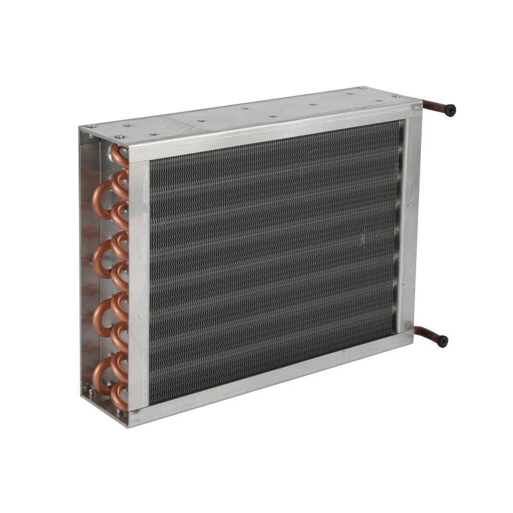
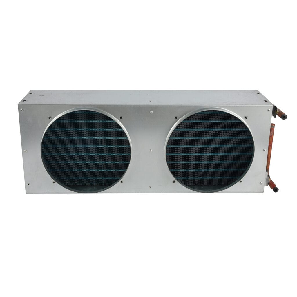
Custom copper tube condensers designed for reliable heat dissipation in commercial and industrial refrigeration systems.
Copper tube condensers are selected by combining tube construction with the heat-rejection duty, airflow path and installation interface. This category is for buyers evaluating copper tube options for commercial, industrial and related refrigeration equipment. To make the review useful, provide the system role, target condition, ambient range, available envelope, tube or port size, fin or frame arrangement, mounting, airflow and any existing drawing or sample. Material and performance details should be confirmed for the exact configuration rather than inferred from the category name.
Showing all 2 results
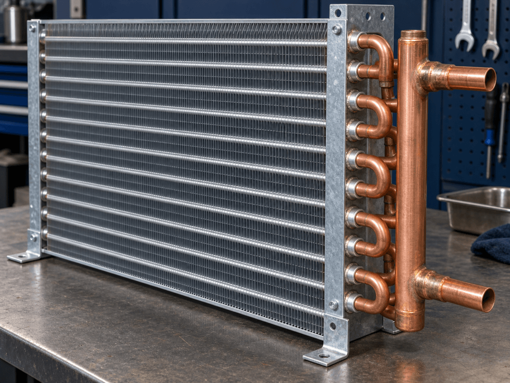
The product view highlights copper tube routing, fin or frame arrangement and connection orientation. Confirm tube size, circuit layout, dimensions, mounting method, surface requirements and port locations rather than selecting from the category name alone.

Copper tube condensers can be specified for commercial and industrial refrigeration assemblies with different heat-rejection layouts. Use the application view to review airflow, ambient conditions, connection access and the condenser's position in the circuit, then share the design conditions for confirmation.
Check: Provide equipment type, target condition, ambient range and heat-rejection information if known
Consider: Sets the context for reviewing the copper tube assembly.
Check: State tube size, fin or frame details, material combination and coating requirement if known
Consider: Identifies the correct construction.
Check: Share dimensions, mounting, air direction, service clearance and port positions
Consider: Confirms installation and system fit.
The category identifies a copper tube condenser family; confirm tube size, fin or frame arrangement, material combination and connection details from approved data.
Review the tube, fin, frame, supports, airflow and mounting as one assembly rather than comparing tube material alone.
Confirm ports, bends, working-fluid information if known, fan arrangement and available service access before release.
Confirm tube layout, heat-transfer surface, frame dimensions, connection size and mounting points
Why it matters: Different equipment duties may require different construction details.
| Parameter | Information to provide | Why it matters |
|---|---|---|
| Application and duty | Commercial, industrial, display, cold-storage or other equipment; duty and target condition if known | Defines the review context. |
| Tube and fin details | Tube size, fin or frame arrangement, material combination and coating | Identifies the construction and environment questions. |
| Envelope and mounting | Dimensions, fixing points, airflow direction, bends and clearance | Confirms physical fit. |
| Connections | Port or tube size, orientation, connection method and working-fluid information if known | Confirms system interface. |
| Quantity and reference | Drawing, sample, existing part and estimated quantity | Supports an accurate quotation. |
| Choice area | What changes | Confirm before choosing |
|---|---|---|
| Copper tube condenser | Tube, fin or frame and connection details define the assembly | Confirm tube size, material combination, airflow, mounting and duty. |
| Wire tube condenser | Wire, tube, plate or layer details define a different packaging interface | Confirm support, envelope, airflow, mounting and connections. |
| Replacement decision | Material labels alone do not establish interchangeability | Compare approved dimensions, ports, mounting, airflow and system role. |
Condenser selection must fit the equipment envelope and airflow arrangement
Confirm: Provide application, ambient, duty, dimensions and connection details.
Larger assemblies require system duty, fan and service interfaces to be reviewed together
Confirm: Send layout, heat-rejection information, mounting and electrical data.
Cabinet or room constraints affect airflow and access
Confirm: Confirm location, ventilation, clearances and existing-part reference.
Confirm tube, fin, frame, support, coating and connection details for the exact configuration.
Match envelope, ports, bends, fixing points, airflow and service clearance to the approved drawing.
State the required dimensional, leak, connection or finish records and confirm what is available.
Provide application, target condition, ambient and duty information if known
Why it matters: Establishes the technical basis.
State tube size, fin or frame arrangement, material, coating and known connection requirements
Why it matters: Helps identify the exact configuration.
Send dimensions, mounting, airflow, ports, bends and photos
Why it matters: Enables fit review.
Share quantity, drawing revision and inspection needs
Why it matters: Supports a traceable quotation.
Confirm tube size, fin or frame arrangement, material combination, connections, envelope, airflow, mounting, duty and ambient condition.
Not automatically. Compare the complete construction, available space, airflow, connections, mounting and system duty.
Send the application, drawing or sample, dimensions, tube and port details, airflow, ambient condition, quantity and required documentation.
Provide it when known; it helps define the system interface and avoids assumptions.
List the project-specific dimensional, connection, leak or finish checks required for approval.
Use it to organize condenser duty, airflow and quotation fields.
Use it to prepare fin spacing, airflow and cleaning questions.
Use it when the copper tube assembly is part of an industrial system.
A clear RFQ helps the team review the right category, construction and interface. Use the checklist below as a practical starting point, then provide the category-specific details shown above.
State the equipment, target condition, ambient environment and expected duty.
Share dimensions, mounting points, connections, airflow direction and service clearances.
For fans and motors, include voltage, frequency, control signal, rotation and wiring.
Attach the old part, drawing or sample and state quantity, revision and documentation needs.
Share your application, drawings and operating requirements so our team can review the details of your project.