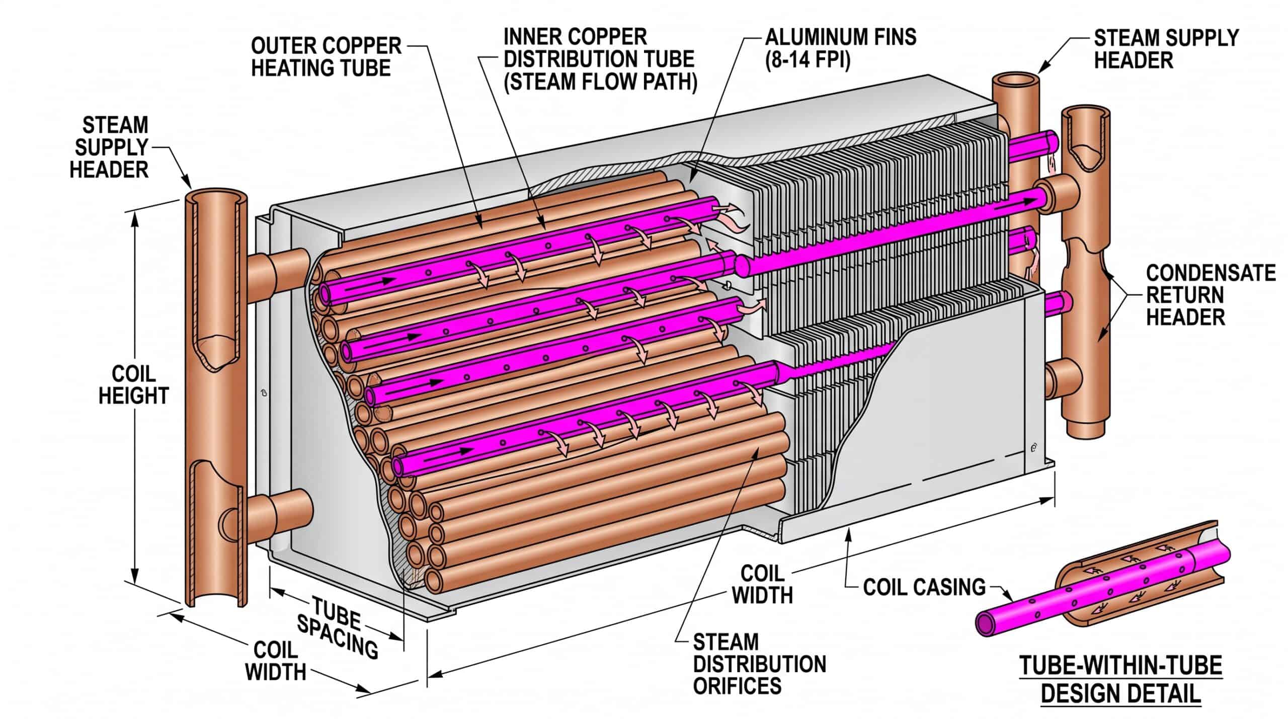
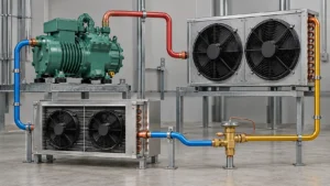
A steam distribution coil uses tube-within-tube construction to distribute steam evenly through inner headers, preventing freeze damage in HVAC systems.
When your facility’s heating system fails during a cold snap, the culprit is often a frozen standard steam coil. Steam distribution coils are engineered specifically to prevent freeze-ups in applications where outdoor air meets steam heating. This guide walks you through the design requirements, material choices, and selection criteria so you can spec the right coil for your project.
What Is a Steam Distribution Coil?
A steam distribution coil is a non-freeze heat exchanger featuring concentric tube construction where steam flows through an inner tube to multiple distribution points before heating air in the outer tubes.
Unlike standard steam coils that feed steam directly into heating tubes, distribution coils use a tube-within-a-tube design. The inner tube carries live steam to multiple header points along the coil length, ensuring even steam distribution even when outdoor air temperatures drop below freezing. This prevents the temperature stratification that causes standard coils to freeze and crack.
How Distribution Coils Differ from Standard Steam Coils
Standard steam coils feed steam into one end of parallel tubes. Cold outdoor air can cool the tubes faster than steam replenishes heat, creating frozen sections. Distribution coils solve this by:
- Running a steam distribution tube inside each heating tube
- Feeding steam simultaneously to multiple points across the coil face
- Maintaining positive steam flow even in low-load conditions
The result: no cold spots, no freeze damage, and no emergency shutdowns in winter.
When to Specify a Distribution Coil vs. Standard Steam
| Condition | Standard Steam Coil | Steam Distribution Coil |
|---|---|---|
| Outdoor air temperature | Above 32°F (0°C) | Below 32°F, especially -20°F to 20°F |
| Air velocity over coil | Constant, moderate | Variable or low during startup |
| Freeze risk | Low | High (makeup air units, rooftop units, preheat sections) |
| Steam pressure | 2–15 PSIG | 2–50 PSIG (standard construction) |
| Application | Interior recirculation | Outdoor air handling, economizer modes |
If your air handler pulls outdoor air in winter or operates in economizer mode, spec a distribution coil. Standard coils will freeze.
Types of Steam Distribution Coil Construction
Steam distribution coils come in single-pass and multi-pass tube configurations, with material choices driven by steam pressure and corrosion risk.
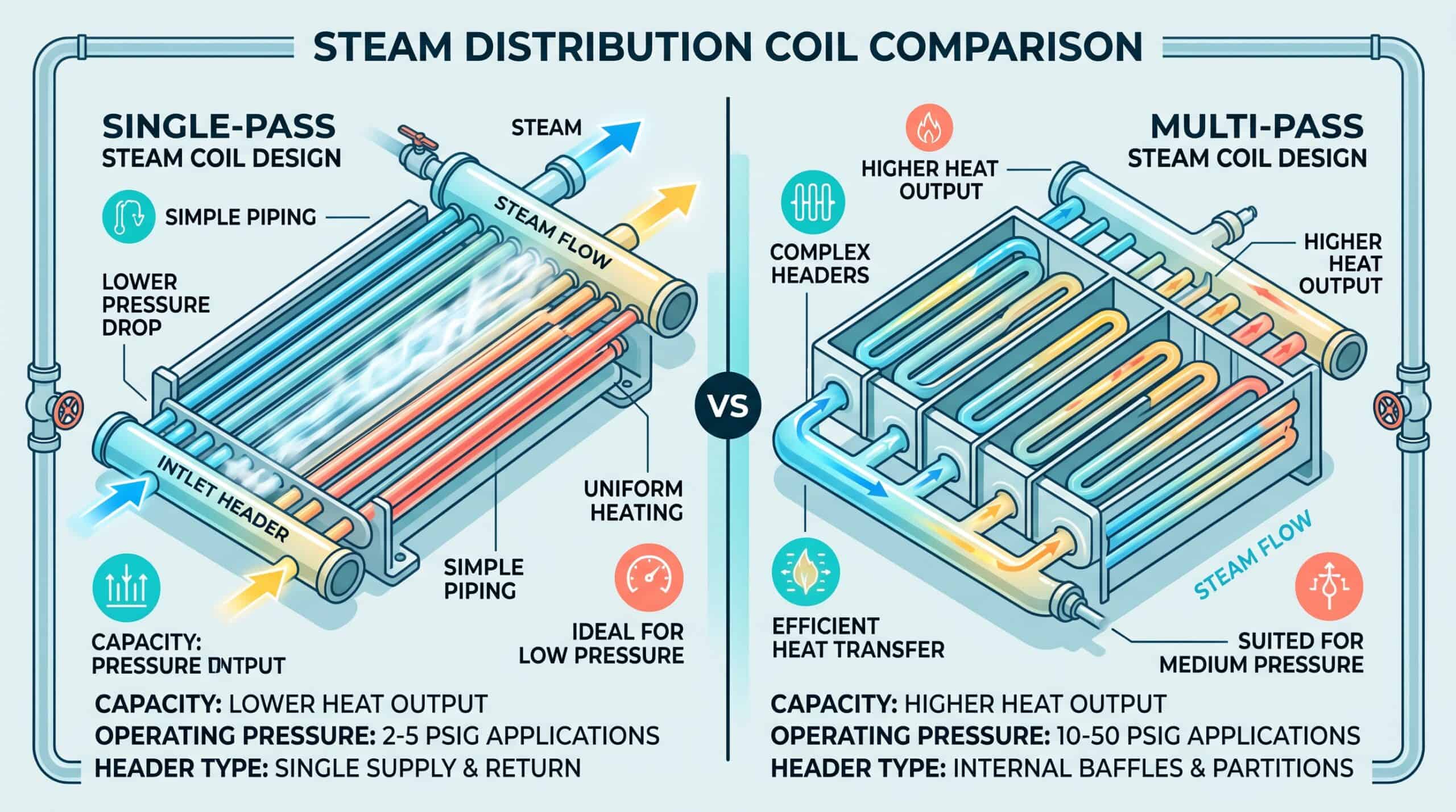
Single-Pass Distribution Design
In single-pass coils, steam enters one header, travels through the inner distribution tubes across the full coil width, and exits the opposite header. Condensate drains by gravity through the same path.
Advantages:
– Lower pressure drop
– Simpler piping
– Better for low-pressure steam (2–5 PSIG)
Typical applications: Small makeup air units, unit heaters, preheat coils under 10 tons heating capacity.
Multi-Pass Distribution Design
Multi-pass coils divide the coil face into sections (typically 2 to 4 passes). Steam makes multiple horizontal runs, increasing residence time and heat transfer.
Advantages:
– Higher heat output per square foot of face area
– More compact coil assemblies
– Better control at partial loads
Tradeoffs: Higher steam pressure required (10–50 PSIG), more complex headers, requires proper condensate drainage design.
Typical applications: Large rooftop units (20+ tons), industrial makeup air systems, process air heating over 100,000 CFM.
Material and Tube Specifications
| Component | Standard Material | Upgraded Options | When to Upgrade |
|---|---|---|---|
| Outer tubes (air side) | Copper | Copper-nickel (90/10), stainless 304 | Coastal installations, corrosive fumes |
| Inner distribution tube | Copper | Stainless 304, stainless 316 | Steam pressure >50 PSIG, high-temperature superheated steam |
| Tube fins | Aluminum (8–14 FPI) | Copper, epoxy-coated aluminum | High humidity, washdown environments |
| Headers | Copper | Steel (carbon or stainless) | Steam pressure >100 PSIG, large coils |
| Casing | Galvanized steel | Stainless 304 | Outdoor exposure, corrosive environments |
Fin-per-inch (FPI) selection:
– 8 FPI: High-dust environments, large particulate (warehouses, factories)
– 10–12 FPI: Standard commercial HVAC (offices, retail)
– 14 FPI: Clean environments where maximum heat transfer matters (labs, clean rooms)
Higher FPI increases heat transfer but also increases air-side pressure drop and fouling risk.
Industry Applications and Use Cases
Steam distribution coils dominate in outdoor air heating, makeup air systems, and any application where freeze protection is non-negotiable.
Commercial HVAC Preheat Sections
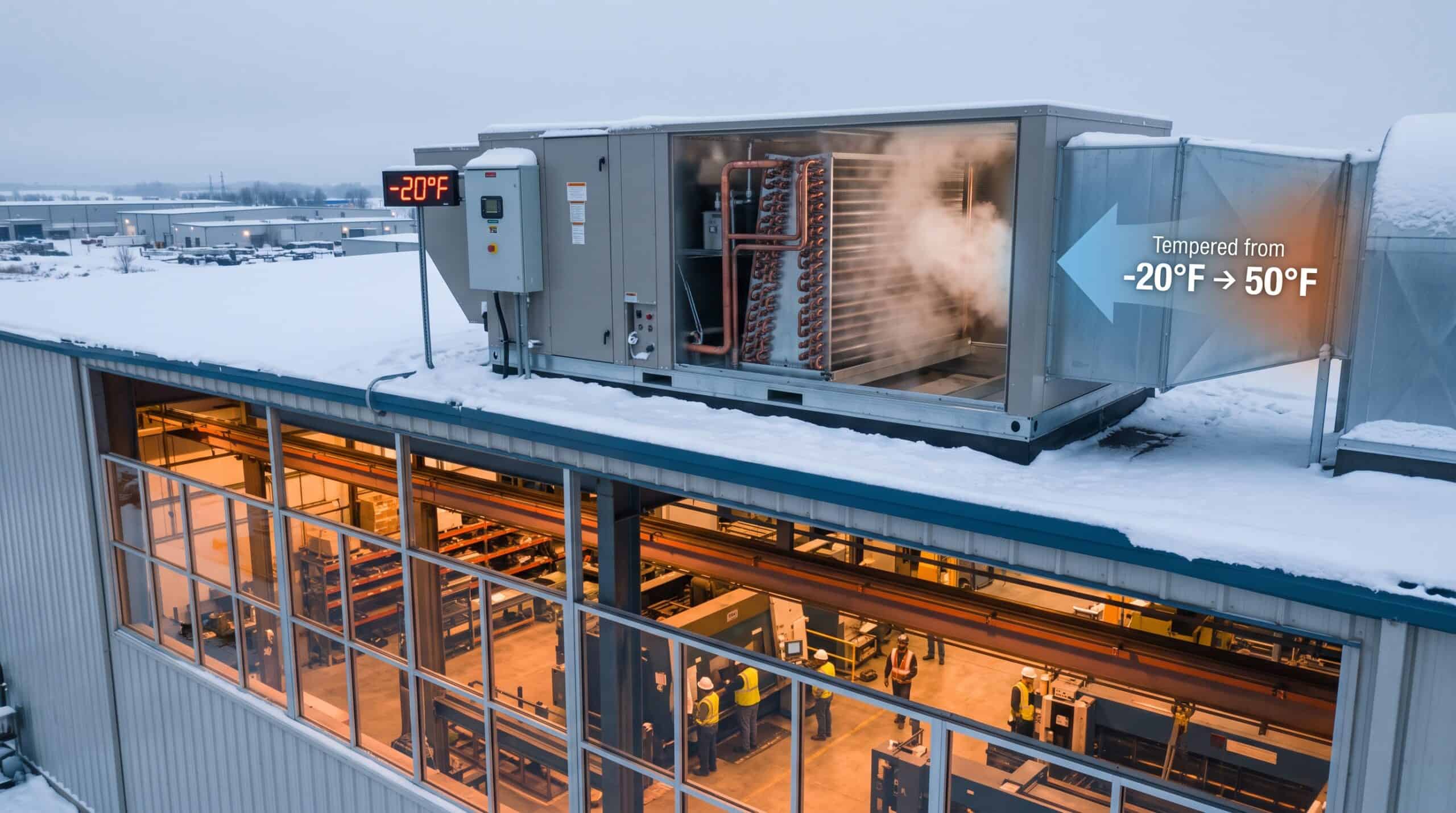
In cold climates, rooftop units and air handlers that introduce outdoor air use distribution coils in the preheat section. These coils bring outdoor air from -20°F up to 40–50°F before it reaches the main heating coil or heat recovery unit.
The preheat function is critical. Without it, freezing outdoor air hitting the main heating coil can create ice buildup that blocks airflow within hours. In a typical northern climate installation, the preheat coil handles the heaviest temperature lift while the main coil fine-tunes to setpoint. This two-stage approach also protects downstream components like heat recovery wheels and cooling coils from thermal shock.
Real-world example: A 50,000 CFM rooftop unit in Minneapolis uses a 4-row steam distribution coil at the outdoor air intake. Steam pressure: 15 PSIG. During January cold snaps (outdoor air at -15°F), the coil maintains 45°F discharge without freeze risk, even during morning warm-up when air velocity is low. The facility manager reports zero freeze-related service calls since installing the distribution coil in 2019, compared to three coil replacements in the previous five years with standard steam coils.
Modern building codes in cold climates often require preheat coils for any system bringing in more than 30% outdoor air. ASHRAE Standard 90.1 specifies minimum preheat temperatures based on climate zone, and most engineers default to steam distribution coils rather than risk freeze damage with standard designs.
Industrial Makeup Air Units
Manufacturing facilities with exhaust systems (paint booths, welding bays, chemical processing) require continuous makeup air. Distribution coils heat large volumes of outdoor air, often 50,000 to 500,000 CFM, while tolerating the dust and particulate common in industrial settings.
Why distribution coils: Standard coils freeze during weekend shutdowns when steam flow drops but outdoor air dampers remain partially open. Distribution coils maintain steam flow to all tubes even at 10% load.
Industrial applications present unique challenges. Welding facilities generate metal particulate that fouls fins faster than office HVAC. Paint booths require explosion-proof electrical classifications, making steam heating the safer choice over electric. Chemical plants may have corrosive atmospheres that demand stainless steel construction.
Sizing for industrial makeup air differs from commercial HVAC. Face velocities typically run 600-800 FPM to keep equipment footprints manageable, but this requires careful attention to pressure drop. An automotive paint facility we worked with needed 200,000 CFM of makeup air heated from 0°F to 70°F. The final design used three parallel 6-row distribution coils at 25 PSIG steam, each handling 67,000 CFM. Fin spacing was set to 8 FPI because the facility welds aluminum, and fine particulate was clogging the original 12 FPI coils every six weeks.
Control strategy matters in industrial settings. Many facilities use on-off steam control to simplify maintenance, accepting the temperature swing rather than dealing with modulating valve failures. Others use staged control with multiple coil sections, bringing sections online as outdoor temperature drops. The best approach depends on process sensitivity and maintenance capability.
Process Air Heating in Food and Pharma
Food processing (drying ovens, curing rooms) and pharmaceutical clean rooms need precise, contamination-free air heating. Steam distribution coils provide:
- No combustion byproducts (unlike gas-fired heaters)
- Uniform air temperature across the full coil face (critical for process consistency)
- Cleanable construction (sanitary tube-and-fin designs, washdown-rated casings)
A pharmaceutical tablet coating line uses a steam distribution coil to heat 30,000 CFM of air to 120°F ±2°F. The coil operates 24/7 and is cleaned monthly with CIP (clean-in-place) protocols.
How to Select the Right Steam Distribution Coil
Selecting a steam distribution coil requires matching coil rows, fin density, and steam pressure to your heating load, outdoor design temperature, and airflow characteristics.
Start with these five design inputs:
- Heating load (BTU/hr): Calculate from airflow (CFM), temperature rise (ΔT), and air density:
BTU/hr = CFM × ΔT × 1.08 - Entering air temperature (EAT): Outdoor design temperature (99.6% or 99% for your location)
- Leaving air temperature (LAT): Desired discharge temperature after the coil
- Airflow (CFM) and face velocity (FPM): Face velocity = CFM ÷ coil face area
- Available steam pressure (PSIG) and steam quality: Dry saturated steam is standard; wet steam reduces capacity
Coil Row Selection
More rows = more heat transfer surface = higher capacity. But also higher air-side pressure drop and cost.
| Application | Typical Rows | Reasoning |
|---|---|---|
| Mild preheat (outdoor air 20°F → 50°F) | 2–3 rows | Modest ΔT, low freeze risk |
| Cold climate preheat (-20°F → 50°F) | 4–6 rows | Large ΔT, need redundancy for freeze protection |
| Process heating (precise temperature control) | 4–8 rows | High capacity, tight control, often modulating steam valve |
Real-world guideline: For every 10°F of temperature rise per row, expect approximately 0.15–0.25 in. w.g. air-side pressure drop at 500 FPM face velocity.
Fin Density and Face Velocity Tradeoffs
Higher fin density increases heat transfer but also increases pressure drop and fouling potential.
Design rule of thumb:
– Face velocity 400–600 FPM: Standard for most commercial HVAC; allows 10–12 FPI
– Face velocity 300–400 FPM: Low-velocity designs for low fan power; can use 12–14 FPI
– Face velocity 600–800 FPM: High-velocity designs (space-constrained); limit to 8–10 FPI to control pressure drop
If your air handler serves a dusty environment (warehouse, foundry), drop to 8 FPI and plan for quarterly coil cleaning.
Steam Pressure and Valve Control Strategy
Steam distribution coils operate across a range of pressures. Higher pressure increases steam temperature and heat transfer driving force, but also increases system cost and safety requirements.
Pressure-capacity relationship:
– 2–5 PSIG steam: ~220–230°F steam temperature; suitable for small coils, low ΔT applications
– 10–15 PSIG steam: ~240–250°F steam temperature; standard for commercial HVAC preheat
– 30–50 PSIG steam: ~270–300°F steam temperature; industrial makeup air, large process heating loads
Control valves: Most systems modulate steam flow with a globe valve or butterfly valve controlled by a discharge air temperature sensor. Two-position (on/off) control works for non-critical applications but risks freeze-ups during rapid load changes.
Common Sizing Mistakes to Avoid
We’ve seen these errors cost projects time and money:
| Mistake | Consequence | Fix |
|---|---|---|
| Undersizing face area (excessive face velocity >800 FPM) | High air-side pressure drop, increased fan power, noise | Increase coil dimensions or reduce airflow |
| Specifying standard steam coil for outdoor air | Freeze damage, coil replacement in first winter | Always spec distribution coil for outdoor air below 40°F |
| Using too many fins (14 FPI in dusty environment) | Coil clogs in weeks, capacity drops 30–50% | Drop to 8 FPI, install upstream filtration |
| Inadequate condensate drainage | Water hammer, reduced capacity, premature tube failure | Pitch coil 0.5–1° toward drain, use vacuum breaker, size trap properly |
| No isolation valves | Cannot service coil without shutting down entire steam system | Install upstream/downstream isolation valves and bypass |
Steam Distribution Coil Installation Best Practices
Proper installation is as critical as proper selection. Here’s what separates a reliable system from a service-call generator.
Piping and Trap Configuration
Condensate removal makes or breaks a steam coil. Distribution coils produce condensate as steam transfers heat; that condensate must drain continuously or it floods tubes and kills capacity.
Mandatory components:
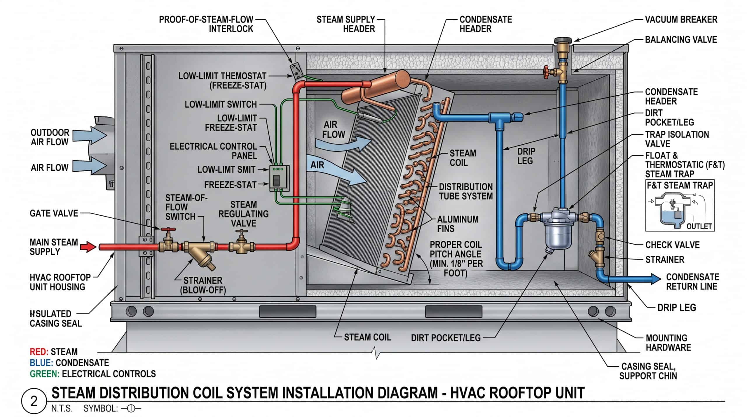
– Steam trap at condensate outlet: F&T (float & thermostatic) traps are standard for modulating loads; inverted bucket traps for on/off control
– Dirt leg before trap: 12–18 inches of vertical pipe to collect sediment before the trap
– Vacuum breaker on return side: Prevents negative pressure that sucks condensate back into coil
– Drip leg at steam supply: Removes condensate from supply line before it enters coil
Pitch requirements: Coil must pitch toward the condensate outlet, typically 0.5 to 1 inch per 10 feet of coil length. Horizontal coils installed dead-level will flood and lose 30% capacity within weeks.
The most common installation mistake is undersizing the condensate return line. Steam collapses to roughly 1/1600th its volume when it condenses, but the liquid still needs to drain away quickly. Use the same pipe size for condensate return as for steam supply, and size the steam trap for 3-4 times the calculated condensate load to handle startup surges.
Trap selection matters more than most installers realize. Float and thermostatic traps work well for modulating systems because they discharge condensate continuously, maintaining a water seal that prevents live steam from blowing through. Inverted bucket traps are more forgiving of dirt and water hammer but cycle intermittently, which can cause temperature fluctuations in sensitive applications. Thermostatic traps are compact and cheap but fail open, meaning a failed trap floods the coil with condensate.
Location of the trap is equally important. Install it at least 12 inches below the coil condensate outlet to ensure gravity drainage. If the mechanical room layout forces the trap above the coil, you’ll need a condensate pump, which adds cost and another failure point. Where possible, route piping to allow gravity drainage all the way back to the boiler or condensate receiver.
Freeze Protection and Low-Limit Controls
Even distribution coils can freeze if you lose steam supply unexpectedly. Install these safeguards:
- Low-limit thermostat downstream of coil: Set to 35–38°F; shuts down outdoor air damper or fan if discharge air drops below setpoint
- Freeze-stat with manual reset: Capillary tube runs across coil face; trips at 35°F and requires manual reset (prevents automatic restart with frozen coil)
- Proof of steam flow: Pressure or temperature sensor on steam supply; interlocked with outdoor air damper to prevent outdoor air introduction if steam is lost
The proof-of-flow interlock is non-negotiable. We’ve seen multiple cases where a boiler tripped offline overnight, the building automation system kept calling for outdoor air, and by morning the coil was a block of ice. The repair cost $15,000 and took three days. A $200 pressure switch would have prevented it.
Freeze-stat placement is critical. The capillary bulb must contact the coil leaving-air side, typically stretched across several tubes to average the temperature. Mount it where you can see the trip indicator from ground level. If the freeze-stat trips during occupied hours, you want to know immediately, not discover it when someone complains about cold air.
Some designers add a low-temperature cutout on the steam supply line as a backup. If steam temperature drops below 200°F, something is wrong (either the boiler is failing or the steam trap is stuck open and flooding the coil with condensate). This cutout can trigger an alarm before the coil actually freezes, giving you time to respond.
Glycol preheat coils offer an alternative freeze protection strategy. Install a small glycol coil upstream of the steam distribution coil to temper outdoor air from -20°F to 20°F, then let the steam coil handle the final rise to setpoint. The glycol coil can’t freeze, and the steam coil only sees air above freezing. This adds first cost and complexity but eliminates freeze risk entirely. It’s common in hospitals and data centers where downtime is unacceptable.
Testing and Commissioning Requirements
After installation, verify coil performance before accepting the system. Here’s the checkout sequence:
- Leak test: Pressure-test coil to 1.5× operating pressure (typically 315 PSIG for standard construction) with nitrogen before connecting steam
- Steam trap operation: With steam flowing, confirm trap cycles properly (F&T trap should cycle every 30–90 seconds under load)
- Temperature profile: Measure discharge air temperature across the coil face at multiple points; variation should be <5°F
- Capacity verification: Measure airflow, EAT, LAT, and calculate actual BTU/hr; should be within 10% of design
- Control response: Simulate load changes and verify steam valve modulates smoothly without hunting
Record baseline data: Document EAT, LAT, steam pressure, and air-side pressure drop at full load. This is your reference for future troubleshooting.
The leak test catches manufacturing defects and shipping damage before you introduce live steam. Use dry nitrogen, not air (moisture in compressed air can cause corrosion). Hold pressure for 30 minutes minimum. Any pressure drop indicates a leak. Common leak points are header-to-tube joints and threaded connections. Fix all leaks before proceeding. A leak that seems minor at test pressure will blow condensate across the mechanical room at operating temperature.
Temperature profiling requires multiple measurements. Place thermocouples or infrared spot readings at nine points across the coil face (three horizontal positions × three vertical positions). Temperature variation beyond 5°F indicates uneven steam distribution, often from a plugged distribution tube or improper coil orientation. If one corner runs cold, check that the coil is pitched correctly and the condensate is draining.
Capacity verification is where you confirm the coil actually delivers the design heating load. Measure airflow with a pitot tube traverse or calibrated flow hood, not from the fan schedule (actual airflow is often 10-20% different from design). Measure temperatures with calibrated instruments, not the building automation system sensors (they drift). Calculate BTU/hr and compare to the submittal data. If you’re more than 10% low, check for fouled fins, inadequate steam pressure, or incorrect airflow.
Control loop tuning is the final step and the one most often skipped. Set the steam valve to manual and verify it strokes fully open and closed. Switch to automatic and watch how the discharge temperature responds to load changes. The valve should modulate smoothly without oscillation. If you see hunting (valve opening and closing rapidly), increase the controller deadband or add a time delay. Most discharge air temperature controllers work best with a 2-3°F deadband and 30-60 second minimum cycle time.
Future Trends in Steam Distribution Coil Technology (2026 & Beyond)
The steam coil market is shifting toward lower-pressure designs, corrosion-resistant materials, and integration with building automation systems for predictive maintenance.
Low-Pressure Steam Systems
Energy costs and decarbonization pressures are driving facilities to lower steam distribution pressures. New construction increasingly specifies 5–10 PSIG steam (down from the traditional 15–30 PSIG) to reduce boiler energy and enable lower-temperature heat sources (including industrial waste heat recovery and electric boilers).
Impact on coil design: Coils need larger face areas and more rows to compensate for reduced steam temperature. We’re seeing 6-row and 8-row distribution coils become standard in cold-climate makeup air applications that previously used 4-row coils at higher pressure.
Corrosion-Resistant and Sustainable Materials
Copper supply constraints and price volatility are pushing manufacturers toward alternative materials:
- Stainless steel tubes: 304 and 316 stainless are now cost-competitive with copper-nickel in many applications; superior corrosion resistance in coastal and chemical environments
- Epoxy-coated fins: Extend coil life in humid, corrosive, or washdown applications; add 15–20% to coil cost but double service life
- Recycled content: Major coil manufacturers now offer coils with 30–50% recycled aluminum (fins) and copper (tubes) to meet LEED and green building requirements
Smart Coil Monitoring and Predictive Maintenance
Building automation systems (BAS) now integrate coil-specific sensors for real-time performance tracking:
| Sensor | What It Monitors | Failure Mode It Predicts |
|---|---|---|
| Differential pressure (air side) | Pressure drop across coil | Fouling, fin damage, airflow blockage |
| Discharge air temperature | LAT vs. setpoint | Undersized coil, steam supply issues, trap failure |
| Steam trap temperature | Temperature drop across trap | Trap failure (stuck open or closed) |
| Condensate flow | Volumetric condensate return | Coil flooding, inadequate drainage |
Early pilots show predictive alerts reduce coil-related service calls by 40% and extend average coil life from 12 years to 18+ years.
FAQ
What’s the difference between a steam distribution coil and a non-freeze coil?
They’re the same. “Non-freeze coil” and “steam distribution coil” are industry terms for the same tube-within-tube construction. Both use an inner distribution tube to feed steam to multiple header points, preventing freeze damage. Some manufacturers use “non-freeze,” others use “steam distributing,” but the AHRI standard design is identical.
Can I use a steam distribution coil for hot water instead of steam?
No. Distribution coils are designed for two-phase flow (steam and condensate) with gravity drainage. Hot water systems require different header designs, pressurization, and typically use counterflow tube circuits. If you need freeze protection with hot water, specify a glycol solution (propylene glycol 20–30%) in a standard hot water coil, not a distribution coil.
How often should steam distribution coils be cleaned?
Inspect and clean based on environment. Clean-air commercial HVAC: annually. Light industrial or high-dust environments: quarterly. Food processing or chemical plants: monthly or per cleaning schedule. Signs you need cleaning: air-side pressure drop increases >20% from baseline, discharge temperature drops >5°F at constant load, or visible fin fouling. Use low-pressure water or compressed air; avoid high-pressure steam cleaning that can damage fins.
What steam pressure is required for a distribution coil?
Standard construction supports 2–50 PSIG. Most commercial applications operate at 10–15 PSIG. Higher pressures (30–50 PSIG) are used in industrial process heating or where high face velocities require maximum heat transfer. For steam above 50 PSIG, specify heavy-duty construction with steel headers and pressure-rated flanges. Always check the coil nameplate for maximum allowable working pressure (MAWP).
Why is my steam distribution coil losing capacity?
Check these common causes: (1) Fouled fins: dirt or debris blocking airflow (most common); clean coil. (2) Failed steam trap: condensate flooding tubes; test trap, replace if stuck closed. (3) Inadequate steam supply: boiler undersized or steam pressure too low; measure steam pressure at coil inlet under load. (4) Air in steam lines: poor venting or oversized piping; install air vents at high points. (5) Coil pitched wrong: condensate not draining; re-level unit or re-pitch coil.
Can a standard steam coil be retrofitted to distribution coil?
No. The tube-within-tube construction is integral to the coil assembly and cannot be field-modified. If a standard steam coil is freezing, your options are: (1) replace with a distribution coil (best solution), (2) add a glycol preheat coil upstream (adds complexity and cost), (3) interlock outdoor air dampers with steam flow proof (reduces freeze risk but doesn’t eliminate it), or (4) install electric preheat (expensive to operate). Replacement is almost always most cost-effective long-term.
What’s the typical lifespan of a steam distribution coil?
15–20 years in commercial HVAC with proper maintenance. Factors that shorten lifespan: corrosive environments (coastal salt air, chemical exposure), poor condensate drainage (causes internal corrosion), inadequate filtration (fin erosion from particulate), and freeze-thaw cycles (from improper control). Industrial applications with harsh conditions may see 10–12 years. Clean coils regularly, maintain steam traps, and protect from freezing to maximize life.
Choosing Your Steam Distribution Coil: Next Steps
Steam distribution coils are the reliable choice for freeze-proof air heating in cold climates and outdoor air applications. The tube-within-tube design eliminates the freeze risk that plagues standard steam coils, but only if you match coil construction to your specific load, steam pressure, and environmental conditions.
Start with your design inputs: heating load, outdoor air temperature, airflow, and available steam pressure. Select coil rows and fin density based on those parameters, not on what’s cheapest or in stock. Specify distribution coils, not standard steam coils, for any outdoor air application below 40°F. Finally, ensure proper installation with correct piping, steam traps, and freeze protection controls.
For commercial HVAC projects in cold climates, steam distribution coils often represent less than 2% of total HVAC cost but prevent the downtime and emergency repairs that can shut down a facility for days. That’s a trade worth making.
Related Articles
- HVAC Heat Pump Solutions for Commercial Buildings
- Evaporator Coil Maintenance and Troubleshooting
- Refrigeration System Design Fundamentals
- Commercial HVAC Coil Selection Guide
- Steam Heating System Efficiency Optimization