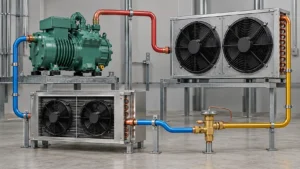
Refrigerant piping links the compressor, condenser, expansion device, and evaporator. Size and route each segment for the selected refrigerant, operating conditions, capacity range, actual line length, elevation, and connected equipment. Suction piping must return oil at the lowest expected load while keeping pressure loss within the compressor limits. Liquid piping must deliver liquid to the metering device without flashing.
An equipment connection is a port size, not a field-line specification. Danfoss’s cold-room piping guide treats line size as a function of refrigerant, capacity, route length, elevation, and operating temperatures. Use the selected compressor and equipment manufacturer’s data for the actual operating envelope.
What are the main refrigerant line types?
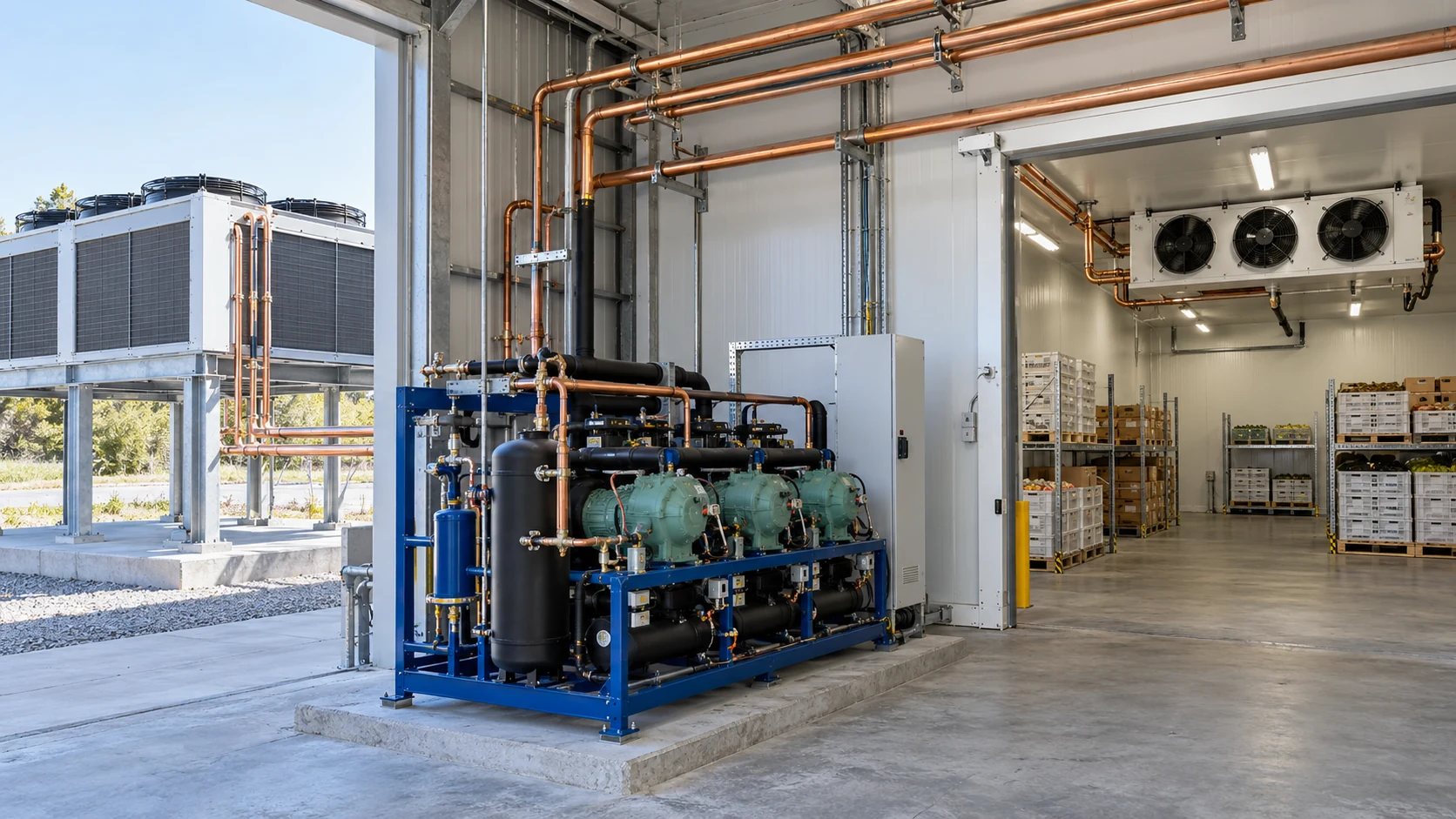
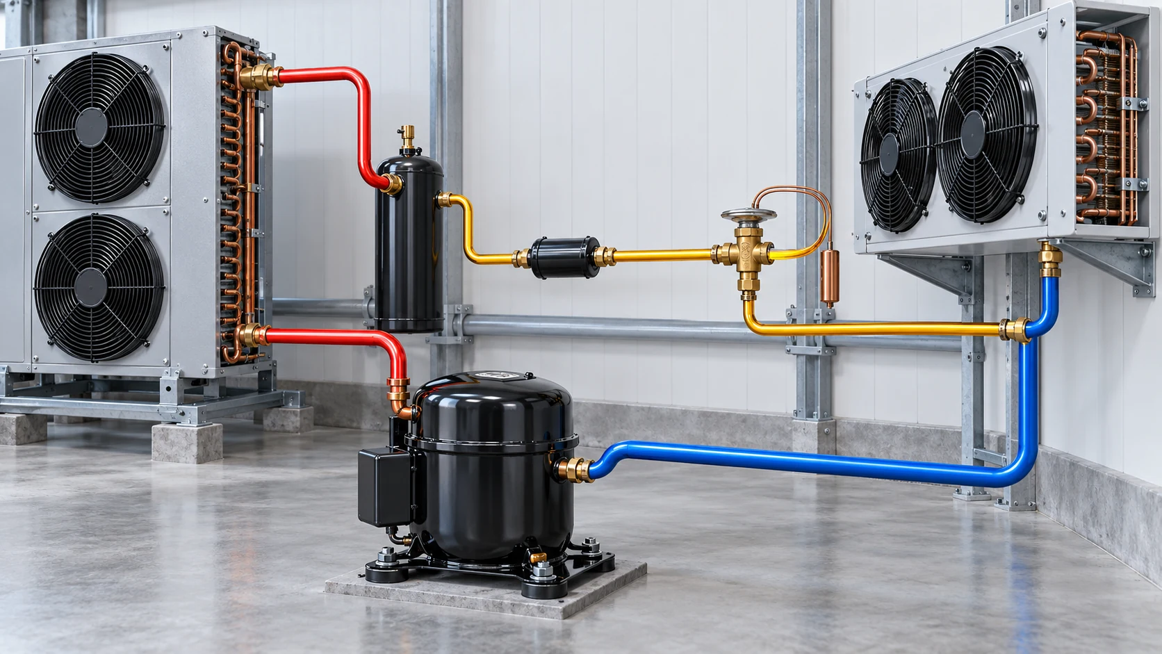
A vapor-compression system usually has three main line functions. Complex systems may add branches, headers, hot-gas defrost lines, economizer lines, or reversible heat-pump paths. The line name describes its refrigerant state and direction of flow, so confirm the actual circuit on the project’s schematic.
- A suction line carries vapor from the evaporator outlet to the compressor inlet. Check oil return at minimum capacity and keep suction pressure drop within the compressor limits.
- A discharge line carries hot gas from the compressor to the condenser. Review pressure rating, temperature, vibration, and refrigerant or oil migration.
- A liquid line runs from the condenser or receiver to the expansion device. Check pressure drop so liquid reaches the metering device without flashing.
- Branches and special-service lines handle headers, hot-gas defrost, economizers, or reversible circuits. Follow the equipment schematic and each component’s instructions.
A line selected at one operating point may not work across the full range. Copeland’s refrigeration manual discusses oil return in branch and main suction lines at minimum load, as well as pressure drop in liquid and hot-gas lines. A single diameter rule cannot cover those different conditions. For the four-stage cycle and the role of each heat exchanger, see the refrigerant cycle guide.
Which inputs determine refrigerant line size?
Start with the operating envelope, not the outside diameter printed on a connector. Record the data below before choosing a pipe chart or selection tool.
- Refrigerant and oil type, including any approved alternatives.
- Required cooling capacity at each design condition, not only the nominal rating.
- Evaporating and condensing temperatures or pressures, superheat, and subcooling where required by the tool.
- Compressor model, capacity-control method, and minimum and maximum operating points.
- Line function: suction, discharge, liquid, hot gas, or a branch.
- Actual route length, equivalent length of fittings, vertical lift or drop, and the location of each component.
- Heat-pump reversing, defrost, shutdown, and part-load conditions that change flow direction or mass flow.
- Tube material, connection method, pressure and temperature limits, insulation, supports, and local code requirements.
Danfoss’s system-design guide lists refrigerant, capacity, line length, elevation, and operating temperature among the inputs for cold-room piping. It also separates the checks for liquid, suction, and discharge lines. Use the selected manufacturer’s instructions or approved sizing software to turn those inputs into a candidate size. For compressor selection context, see Domi’s refrigeration compressor guide.
How do you size refrigerant lines?
Use a repeatable sequence for every segment of the system. Do not select tubing from nominal tonnage alone.
- Fix the design case. Confirm the refrigerant, evaporating and condensing conditions, cooling duty, ambient range, and operating modes.
- Draw the line segments. Mark the suction, liquid, discharge, and special-service lines separately. Record branches, headers, vertical changes, and equipment connections.
- Measure the route. Include straight length, fittings, elevation, and routing restrictions. A schematic that omits the route may not support a final size.
- Select a candidate in the equipment manufacturer’s tool or tables. Use data for the refrigerant and compressor family being specified. Do not transfer a table value to another refrigerant or operating envelope without confirmation.
- Check pressure drop and mass flow. Review each line at the design conditions. The liquid line must maintain liquid delivery to the metering device; suction pressure loss affects compressor inlet conditions.
- Check oil return at the lowest expected load. Variable-speed compressors and staged systems need a part-load check. A line selected only for full load may not move oil reliably when mass flow falls.
- Review installation and pressure limits. Confirm tubing material, pressure rating, joint method, supports, insulation, vibration control, and applicable safety rules.
- Keep the calculation with the drawing. Record the tool or manufacturer reference, assumptions, selected line size, and reviewer so later equipment or refrigerant changes can be checked.
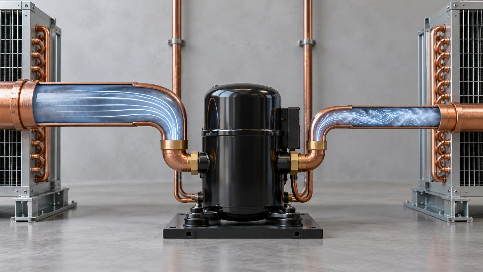
The useful output is a documented design for the specified operating envelope, not a universal table of pipe diameters. If the refrigerant, compressor speed range, evaporating condition, or route changes, run the selection again.
Why is the unit connection size not always the field-line size?
A compressor, condenser, or condensing-unit connection is a component interface. The interconnecting line has its own route, length, flow rate, and elevation. A port and field line may have the same diameter in a particular design, but the port alone does not establish that choice.
In a model-specific Danfoss condensing-unit application guide, the manufacturer warns users not to assume the unit’s suction and liquid connections are the right sizes for interconnecting piping. That guide also calls for sizing across the unit’s capacity range. It is an application example, but it shows why a port dimension alone cannot set the field pipe size. Confirm the approved line schedule in the equipment manufacturer’s data before fabrication or installation. During a drawing review, treat every port as an interface, then check the complete route against the selected equipment data.
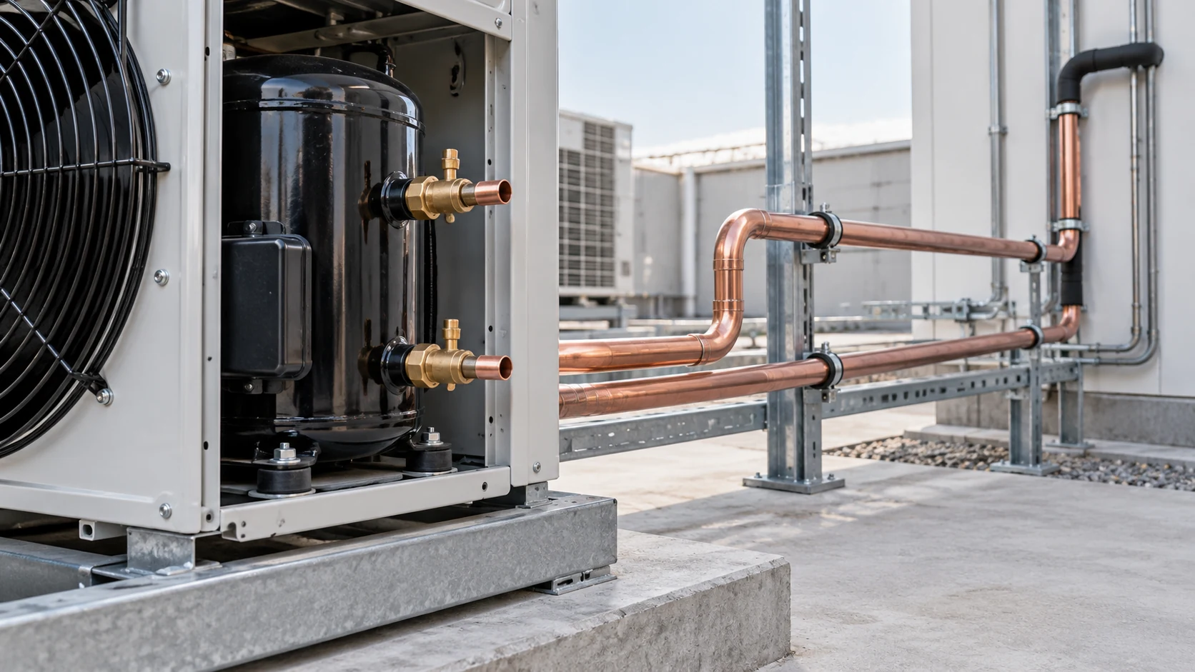
For an OEM package, send the drawing, refrigerant, capacity target, and line schedule together. That gives the reviewer the context to assess a package port against the full interconnecting run.
How do part-load systems change suction-line design?
Part-load operation creates a design tradeoff. A large suction line can reduce pressure loss at full load, but gas velocity may fall too far for oil return when capacity or compressor speed is low. A smaller line can support velocity at low load but create more pressure drop at higher flow.
Some compressor applications use a split or double riser across a wide capacity range. The smaller path can support oil return at reduced capacity; both paths carry flow at higher load. This arrangement depends on the compressor and operating conditions, so it is not a retrofit shortcut. BITZER’s pipe-layout guidance describes split risers for capacity-controlled systems and the need to check oil return at minimum load.
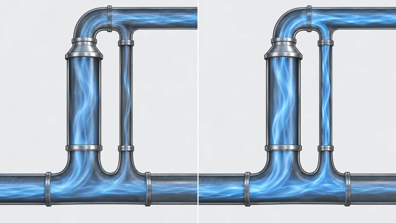
Ask the compressor supplier or system designer to confirm:
- Whether the compressor is fixed-speed, staged, or variable-speed.
- The minimum stable mass flow and speed.
- The expected vertical rise and operating schedule.
- Whether a single riser, split riser, or another arrangement is approved.
- How oil return will be verified during commissioning.
Do not copy a velocity target from one manual into another system. Published values apply to the cited compressor, refrigerant, capacity range, and instructions.
What material should refrigerant piping use?
Copper ACR tubing is common for field connections in many refrigeration applications. ASTM B280-23 specifies seamless copper tube for air-conditioning and refrigeration field service. The standard does not select wall thickness, diameter, joining method, or pressure rating for a particular system.
Material selection must match the refrigerant, pressure and temperature range, component approvals, joint method, environment, and local requirements. CO2 systems operate at pressure conditions that require equipment and piping designed for that application. A2L systems also have refrigerant-specific safety and installation requirements. Confirm the tubing and fittings against the design pressure and the instructions for the exact system.
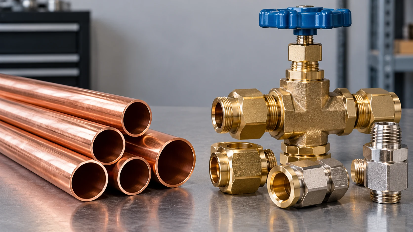
A procurement drawing should state the tube standard and material when known. If the specification is incomplete, list it as an open engineering item rather than assuming that any copper tube or fitting will work.
How do route length and fittings affect pressure drop?
The pipe route affects pressure drop, refrigerant charge, oil movement, service access, and installation cost. Long runs, many elbows, undersized branches, abrupt reductions, and poorly placed rises can change the result that a straight-pipe lookup suggests.
Keep runs as short as the equipment layout allows. Use the fitting and equivalent-length method required by the manufacturer’s sizing tool. Add elevation changes and branch geometry to the model, then check the least favorable operating point. Do not substitute a visual estimate for the pressure-drop calculation.
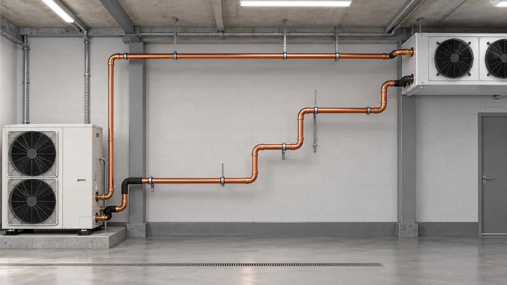
Danfoss’s piping guide advises minimizing unnecessary direction changes and preventing sagging that can create unintended oil traps. Keep service valves, compressor connections, sight glasses, and removable panels accessible. Insulate each line where the equipment instructions and operating conditions call for it.
What should the installation drawing show?
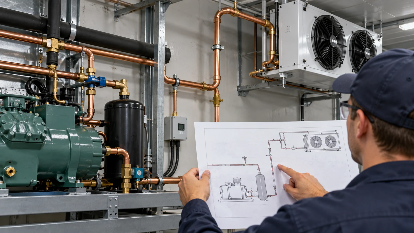
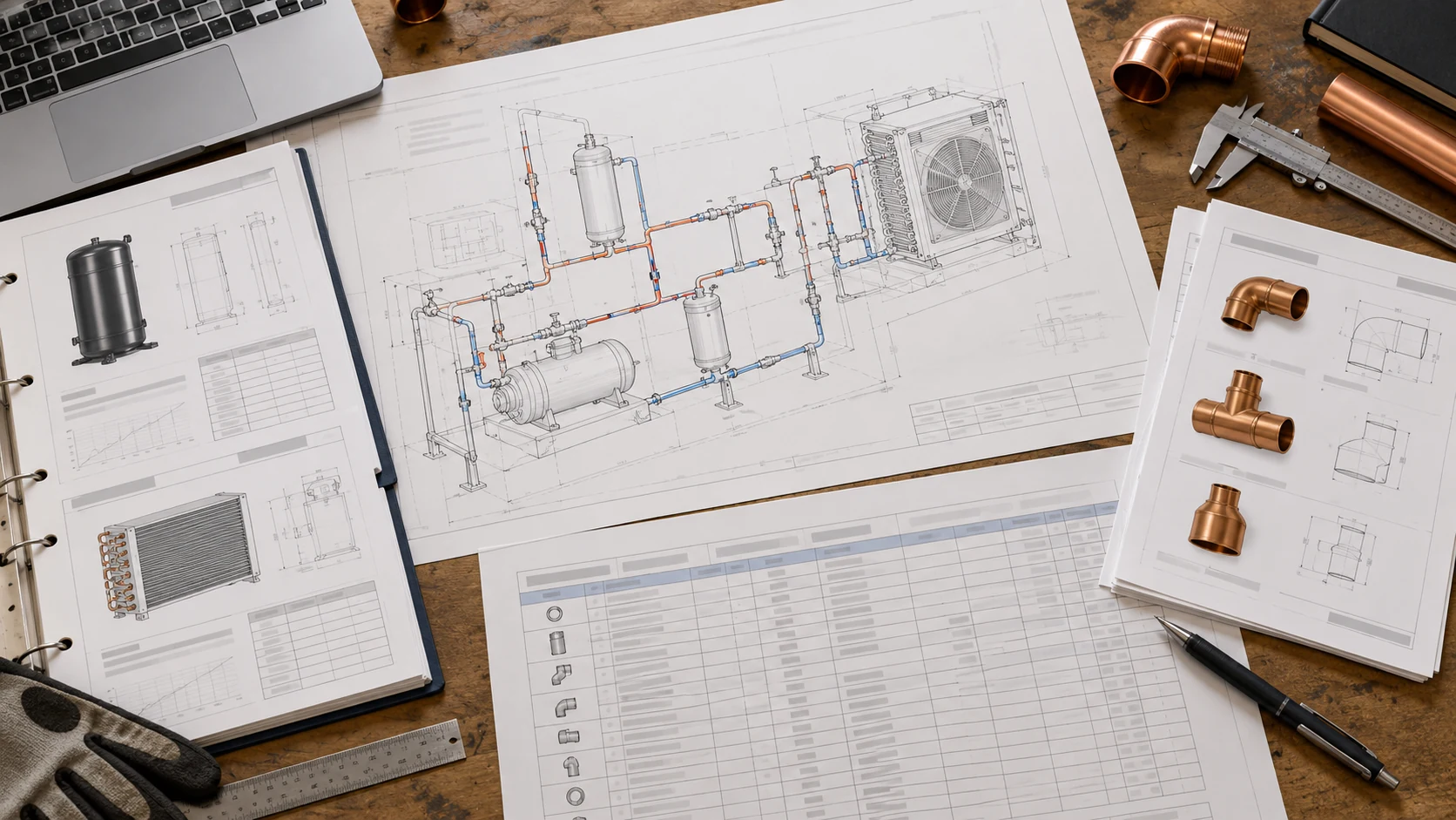
A useful field drawing lets an installer build and inspect the intended route. The generated illustration below shows example drawing elements; it is not construction-ready. List these project-specific items:
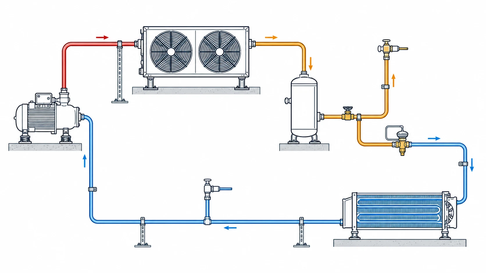
- Flow direction and line function for each segment.
- Pipe material, outside diameter or nominal designation, and wall specification where applicable.
- Fittings, branches, reducers, traps, risers, and isolation or service components.
- Equipment connection locations and the approved connection schedule.
- Insulation boundaries, support points, penetrations, and vibration-control details.
- Design pressure and temperature where needed for material and component selection.
- Special conditions for hot-gas defrost, heat-pump reversal, pump-down, or low-load operation.
- The drawing revision and the source of the sizing data.
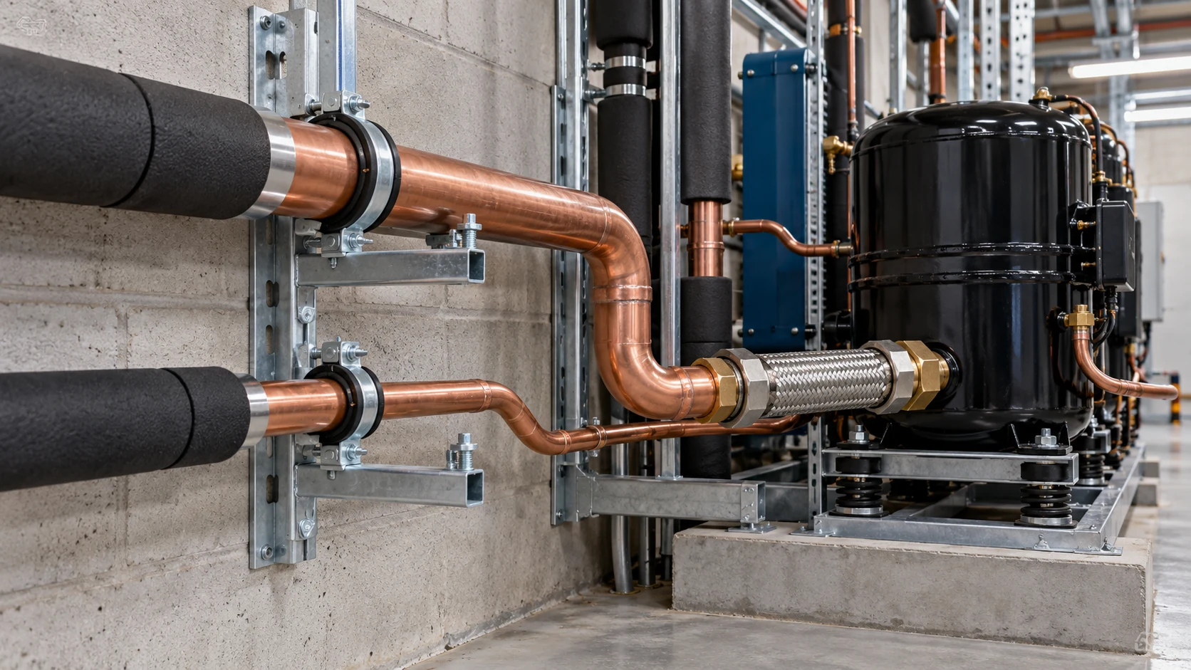
Copeland’s refrigeration manual covers line supports, oil traps, vibration, and tubing protection. Follow the support spacing and joining procedure specified for the equipment and project.
How can commissioning checks confirm the piping design?
Commissioning records should compare actual system behavior with the approved design. A qualified refrigeration technician or engineer can check the operating conditions and the points that matter for the selected equipment.
Record refrigerant, ambient condition, load state, compressor stage or speed, suction and discharge conditions, liquid-line condition, and the measurement locations. Compare pressure loss and operating temperatures with the manufacturer’s limits. For variable-capacity systems, include the lowest operating point that the commissioning plan can safely test.
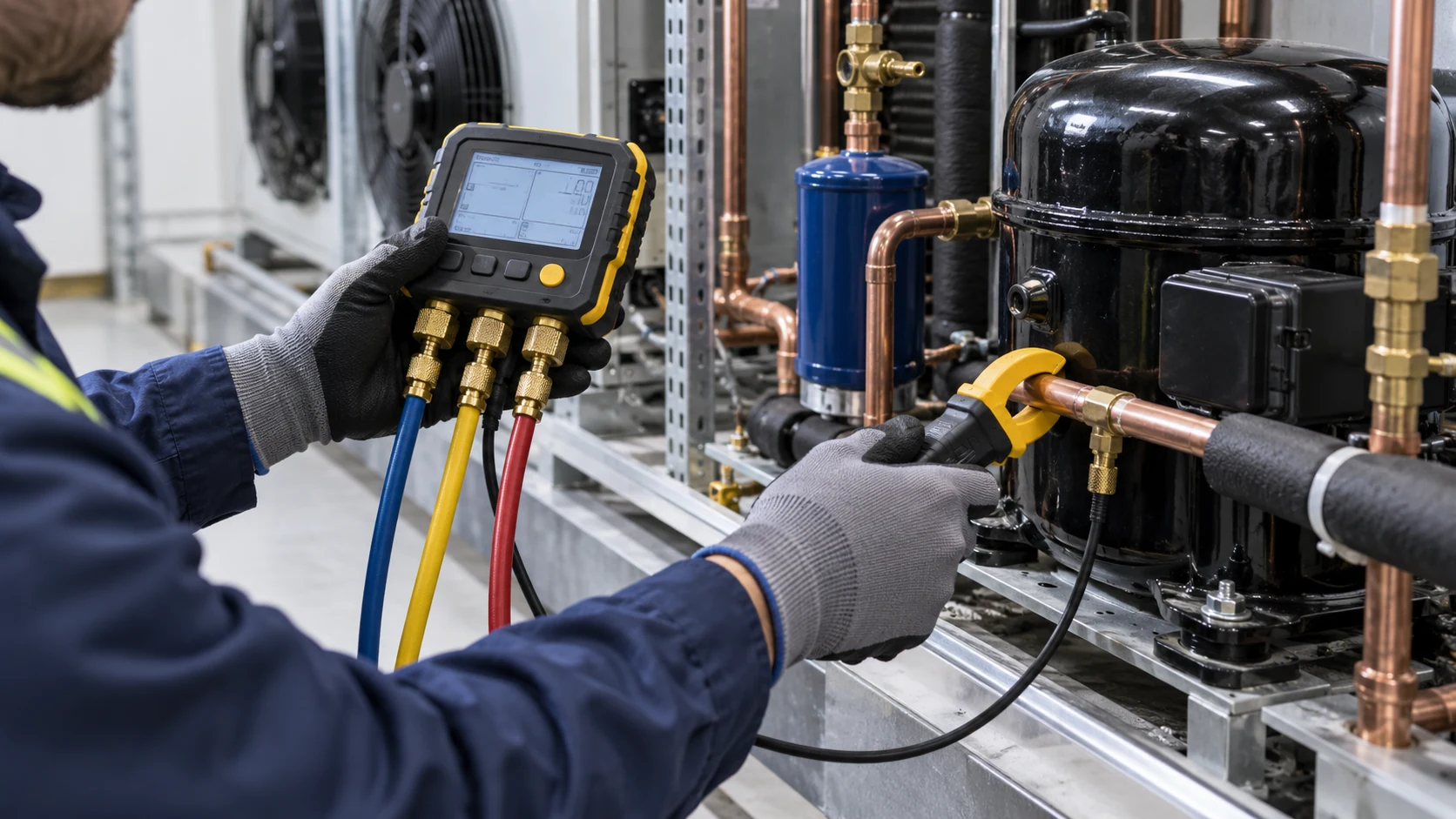
Symptoms such as low suction pressure, poor oil level, flash gas, vibration, or uneven coil performance can have several causes. They do not prove that a pipe is undersized. Confirm instruments, charge, controls, restrictions, airflow, and equipment condition before changing the line design. Refrigerant handling, brazing, pressure testing, and recovery should be performed by qualified personnel using the applicable safety procedures.
What should an OEM include in a refrigerant piping RFQ?
For a useful piping review, send the system boundary and operating case. Include one line schedule with the drawing; a compressor port size alone does not describe the route.
- Application: equipment type, temperature range, indoor or outdoor location, and duty cycle.
- Refrigerant: exact refrigerant, oil, and any approved alternative.
- Capacity and conditions: design duty, evaporating and condensing conditions, ambient range, and minimum and maximum load.
- Equipment: compressor, condenser, evaporator, expansion device, and connection data.
- Route: segment lengths, elevation changes, fittings, branches, and installation limits.
- Materials: tube standard, material, connection method, design pressure, insulation, and finish.
- Operating modes: part load, staging, variable speed, defrost, pump-down, or heat-pump reversal.
- Documents: piping schematic, equipment schedules, sizing reference, and drawing revision.
If the system includes a custom heat exchanger or condensing-unit package, include the piping interface in the same drawing set as the coil duty, refrigerant, connections, and installation envelope. Domi’s engineering page describes support for heat-transfer requirements and drawing review on heat-exchanger projects. Confirm the requested engineering scope with the team before relying on it for complete system-pipe design.
Frequently asked questions
What are the different types of refrigerant pipes?
The three common main line functions are suction, discharge, and liquid. A larger system may also include branches, headers, hot-gas defrost, economizer, or reversible heat-pump lines. The schematic and refrigerant state determine the correct name and design check.
What material is used for refrigerant piping?
Copper ACR tube made to ASTM B280 is common in field refrigeration work. Material and wall specification still depend on the refrigerant, design pressure, temperature, fittings, equipment approval, and code. Do not use a general material label as a substitute for the system specification.
How do you size refrigerant lines?
Use the selected equipment manufacturer’s chart or sizing tool with refrigerant, capacity, evaporating and condensing conditions, route length, elevation, fittings, and full capacity range. Check suction oil return at minimum load and pressure drop at the required operating points.
Are refrigerant line sizes standard?
Tubing is available in standard sizes, but a standard size list does not identify the correct size for a system. Use the refrigerant, operating conditions, line route, capacity, pressure limit, and manufacturer instructions to select the pipe.
Can I use the same size as the compressor connection?
Not automatically. The compressor connection is a port dimension. The interconnecting pipe must be selected for the full circuit and operating range. Check the approved equipment data and line calculation.
Does a larger suction line always improve performance?
No. A larger diameter can reduce friction at higher flow, but it can also reduce gas velocity when the system operates at low capacity. The selection must balance pressure drop and oil return across the actual load range.
Does CO2 use the same refrigerant piping as an HFC system?
Do not assume it does. CO2 systems have different pressure requirements and may need different pipe, fittings, valves, and safety components. Follow the approved CO2 system design and equipment data.
What should I send for a refrigerant piping review?
Send the piping schematic, refrigerant, capacity and operating conditions, component models, line lengths and elevations, fitting layout, material specification, and operating modes. Include the drawing revision and note which values are confirmed versus still under review.
Review the coil and piping interface before release
If your project includes a custom evaporator, condenser, or condensing-unit package, send the drawing, refrigerant, capacity target, operating conditions, and piping connection schedule with the RFQ. Domi’s team describes drawing review and thermal engineering support for heat-exchanger projects. Ask the team to confirm whether the requested piping review falls within the project scope.