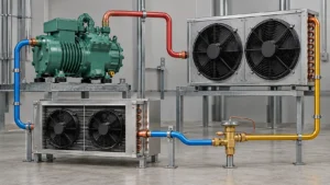
A refrigerator defrost thermostat controls or protects the defrost cycle by responding to evaporator temperature; compatibility depends on the model, temperature range, mounting, connector, and control strategy.
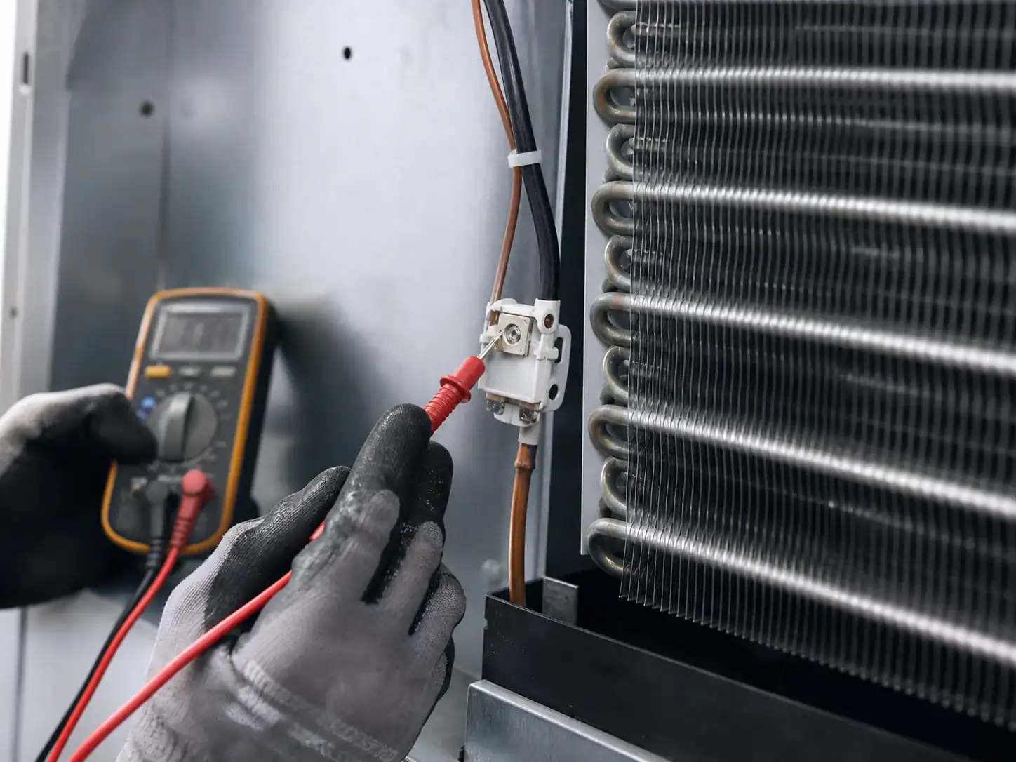
A refrigerator defrost thermostat is not simply a universal on/off switch. It is a temperature-dependent component used to enable, interrupt, or protect a defrost circuit according to the appliance design. In some systems, a mechanical thermostat works with a timer and heater. In others, a thermistor reports temperature to an electronic control, while a separate safety device protects against excessive temperature. The words “defrost thermostat” can therefore describe different component architectures.
If the thermostat is wrong, mislocated, open at the wrong temperature, closed when it should open, poorly clipped to the evaporator, or connected to the wrong control, frost can accumulate or defrost can overheat the cabinet. A refrigerator may be warm, a freezer may work while the fresh-food compartment loses airflow, or cooling may return temporarily after manual defrost.
This guide is for qualified service teams and for OEM engineers, procurement managers, and coil suppliers reviewing a defrost interface. It explains the function, symptom patterns, testing logic, replacement compatibility, and RFQ information required for a defensible part decision. A refrigeration-coil supplier should not be assumed to supply the thermostat or control unless that scope has been confirmed for the project.
The GE automatic-defrost explanation provides useful background on why an appliance needs a controlled defrost process. The GE overview of defrost systems also shows why the component set differs between designs. For model-specific replacement work, use the appliance manufacturer’s part information and service procedure rather than a generic temperature claim.
What a defrost thermostat does
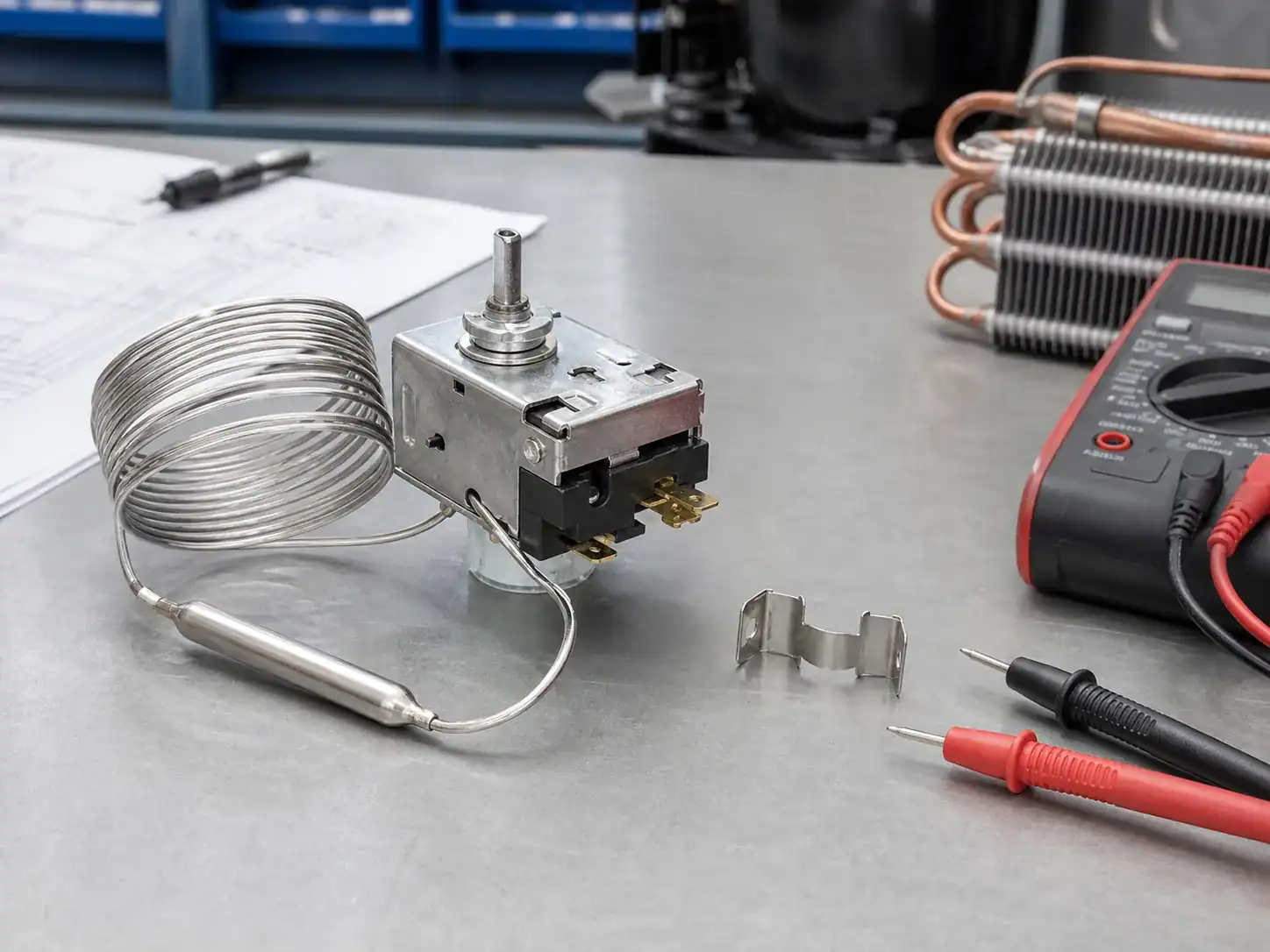
During normal cooling, the evaporator is cold and can collect frost. During defrost, a heater or other approved method raises the temperature around the coil. A mechanical defrost thermostat changes electrical state at a specified temperature range. Depending on the circuit, it may close below a cut-in temperature to allow a defrost heater to operate, then open at a higher cut-out temperature to terminate or protect the cycle. The exact behavior depends on the model and wiring.
An electronic thermistor does not behave like a simple mechanical thermostat. It changes resistance with temperature, and the control interprets the signal. The service manual may list a resistance-versus-temperature curve, connector pinout, sensor placement, and control diagnostic code. Substituting a mechanical thermostat for a thermistor or using an approximate resistance can create an unsafe or ineffective cycle.
Thermostat, thermistor, and safety device are different
| Component | Typical signal | Main purpose | Compatibility risk |
|---|---|---|---|
| Mechanical defrost thermostat | Opens or closes at temperature | Enables or terminates/protects a heater circuit | Wrong cut-in/cut-out, contacts, body, clip or connector |
| Thermistor | Resistance changes with temperature | Reports coil or cabinet temperature to a control | Wrong resistance curve, location, harness or software interpretation |
| Thermal fuse or protector | Opens at an over-temperature limit | Provides a protective interruption | Wrong rating, mounting or replacement reset behavior |
| Timer | Mechanical or electrical command | Starts a defrost interval | Different cycle logic, voltage, connector or indexing |
| Electronic control | Low-voltage or switched output | Coordinates sensors, heater, fan, damper and termination | Model software, relay, input and safety logic |
The part name in a listing is not sufficient evidence of compatibility. Identify the actual component type, circuit role, setpoint or curve, mount, connector, and service part number.
Symptoms associated with a defrost thermostat problem
Evaporator freezes and airflow falls
If the thermostat does not allow a scheduled defrost, the heater may never run. Frost accumulates, fin openings close, the fan pressure requirement rises, and cold air stops reaching the cabinet. The freezer can remain cold at a local surface while the fresh-food compartment warms. The Domi guide to a refrigerator that is not cooling but the freezer works explains why this symptom should start with airflow and defrost evidence.
Defrost runs too long or overheats
If the thermostat does not open at the intended temperature, the heater may continue until a backup protector or control limit acts. Inspect thermal evidence, the heater, the thermostat or sensor position, the control command, and the surrounding materials. Do not bypass a protective device to keep a refrigerator cold.
Cooling returns after a manual defrost
Manual defrost removes the ice but does not show that the automatic cycle will repeat correctly. Record how long the cabinet performs after defrost, whether the heater receives a command, whether the thermostat changes state at the specified temperature, and whether water drains. Recurrence is evidence of an unresolved frost-control path, not proof that the thermostat alone is defective.
The thermostat tests “open” or “closed” unexpectedly
A mechanical thermostat’s state depends on its temperature and design. A room-temperature reading cannot be interpreted without the model’s expected state at that temperature. The component may also be affected by clip position, thermal contact, wiring, or a parallel circuit. Isolate it and follow the service procedure before concluding failure.
How a qualified technician tests the circuit
Electrical work can cause shock, arc, burn, or damage to the control. Disconnect power where the procedure requires it, avoid refrigerant tubing and sharp fins, and use a meter and temperature source suitable for the model. Testing should be performed by a qualified technician.
Identify the circuit before measuring
Read the appliance schematic and locate the thermostat or sensor, heater, timer or control, thermal fuse, connectors, and ground or return path. Photograph wire positions only as a supplementary record; do not rely on memory or color alone. Confirm whether the thermostat is in series with the heater, used as a signal input, or connected to a protection circuit.
Test a mechanical thermostat at defined temperatures
Measure the state at the temperature points specified by the service manual. The test may require cooling or warming the component in a controlled way. Record the starting temperature, the state before and after transition, the direction of temperature change, and the reset behavior. Do not infer a setpoint from a generic thermostat sold for another model.
Test a thermistor against its curve
Measure resistance at controlled temperatures and compare with the approved curve or service table. Check the connector, harness, insulation, sensor body, clip, and thermal contact. A sensor can be electrically correct at room temperature but mechanically wrong on the coil, giving the control a false reading during operation.
Test the control command and heater response
If the thermostat passes, verify that the timer or electronic control requests defrost under the correct service-test conditions. Confirm heater voltage and current where authorized, then observe temperature response, termination, drain flow, fan restart, and cabinet recovery. “Sensor good” and “control command present” are separate findings.
The GE defrost thermostat product information is a useful reminder that model-specific component identification matters. The Whirlpool refrigerator cooling troubleshooting page is a practical example of separating settings, airflow, and system operation before assigning a part.
Thermostat location and evaporator geometry
The component’s location affects the temperature it sees. A thermostat clipped to the wrong tube, moved away from the heater, covered by insulation, or left loose in the air stream may transition at the wrong time even if the part number is correct.
Show the clip and contact surface
An OEM drawing should show the thermostat or sensor clip, tube or fin location, orientation, contact pressure, wire exit, and keep-out zone. If the component is supplied by the customer, mark it as a controlled interface. If the supplier assembles it, define the part number, inspection, and change-notification requirement.
Protect the sensor from false temperatures
The sensor should not read a local hot spot, a cold bypass stream, a loose air pocket, or a heater terminal unless the design intends it. A small geometry change in the evaporator, header, bracket, cover, fin pitch, or heater can change local temperature. Validate the location after a coil revision.
Coordinate the drain and cover
The thermostat or sensor should survive normal moisture and defrost water exposure. The cover should direct airflow and meltwater as intended. A changed cover seal can alter frost distribution and the temperature seen by the component. The Domi refrigeration coil drawing revision-control guide provides the document-control context for connecting such changes to a released revision.
How thermostat failure differs from other faults
Heater fault
An open heater can leave the thermostat apparently normal while frost still builds. Check heater continuity, command, current, mounting, and temperature response. A thermostat replacement will not repair a heater with no electrical or physical response.
Defrost control fault
The thermostat may change state correctly while the timer or control never starts the cycle. Verify the input, output, timing, relay, software state, and wiring. Use a model-specific service test.
Fan or damper fault
The defrost circuit may pass while airflow remains weak because a fan, damper, duct, or return path is blocked. The Domi refrigerator-not-cooling guide gives a broader symptom tree. Do not order a thermostat only because the refrigerator is warm.
Drain or door-seal fault
Water can refreeze below the coil when the drain is blocked, and high moisture entry can create more frost than the normal cycle removes. Inspect gasket, door alignment, installation, drain, pan, and insulation.
Sealed-system fault
A leak, restriction, incorrect charge, or compressor issue can reduce cooling and change the frost pattern. A qualified technician should use pressure, temperature, leak, and electrical evidence. A defrost thermostat does not correct a sealed-system fault.
OEM compatibility checklist
For a replacement thermostat or a coil with a thermostat interface, match the complete specification.
| Compatibility item | Questions for the buyer and supplier |
|---|---|
| Component type | Mechanical thermostat, thermistor, thermal fuse, or other protector? |
| Temperature behavior | Cut-in/cut-out, tolerance, curve, reset, and approved range? |
| Electrical | Voltage, current, contact arrangement, connector, polarity and insulation? |
| Mechanical | Body, clip, tube/fin location, orientation, wire exit and clearance? |
| Environment | Moisture, frost, defrost heat, corrosion, vibration and cleaning exposure? |
| Control | Timer or control input, diagnostic behavior, software assumption and cycle logic? |
| Coil interface | Coil envelope, circuiting, heater, sensor, cover, drain and mounting? |
| Quality | Incoming inspection, continuity/curve check, sample test, traceability and change control? |
If any row is unknown, list it as an open item. Do not fill an unknown temperature or resistance with a proxy from a different model. The Domi custom refrigerator-coil RFQ checklist is a useful internal link for collecting part, drawing, sample, quality, and commercial information.
Defrost thermostat validation for an OEM program
Validate the component in the cabinet and coil assembly, not only on a workbench.
- Confirm initial cabinet temperature, humidity, load, ambient, setpoint, and airflow.
- Run normal cooling long enough to create the representative frost condition.
- Record sensor or thermostat state, control command, heater current, temperatures, and frost distribution.
- Confirm defrost termination or protection at the correct condition.
- Verify drain flow, fan restart, damper state, and post-defrost pull-down.
- Repeat across manufacturing tolerances, ambient conditions, voltage range, and intended loading where required.
- Review abnormal cases such as blocked airflow, high moisture, a stuck relay, sensor displacement, and a blocked drain.
The Danfoss defrost handbook offers system-level context for defrost strategy and control trade-offs. Use the appliance’s own limits and applicable safety standards for the approval decision.
RFQ information for a defrost thermostat or evaporator assembly
Provide the appliance model and serial family, current part number, drawing revision, component photographs, service schematic, thermostat or sensor data, heater data, coil envelope, mounting, tube and connection details, refrigerant, operating temperatures, defrost interval, frost load, drain and cover, fan and duct, materials, inspection, packaging, volume, MOQ, sample quantity, and schedule.
Clarify whether the quote is for a thermostat, a thermistor, a heater, a coil, a coil with heater, or a complete evaporator module. State whether the supplier should review compatibility or only manufacture to a released drawing. Ask for assumptions, exclusions, proposed changes, test records, and change-notification terms.
What not to do with a defrost thermostat
Do not jumper the thermostat or sensor as a permanent repair. Do not substitute an item with a similar shape but unverified temperature behavior. Do not move a clip to a convenient tube without validating the temperature response. Do not change heater power, coil geometry, drain, cover, or control settings without a controlled revision. Do not assume that a refrigerator that cools after manual defrost has a thermostat-only problem.
A step-by-step diagnostic record
The most useful service record shows the relationship between temperature, component state, and airflow. Start with the model, control revision, ambient, cabinet load, setpoints, probe locations, and elapsed time. Record freezer and fresh-food temperatures separately. Note whether the evaporator fan runs, whether the supply vent is cold, whether the return is open, and whether the damper changes state.
Record the frost condition
Photograph the evaporator before defrost if access is safe and allowed. Record whether frost is even across the active area, concentrated at the inlet, limited to one side, or built into a solid layer. Mark the sensor or thermostat position and the heater relationship. The frost pattern can help distinguish a blocked airflow path from low refrigerant flow, but it is not a substitute for qualified pressure and temperature testing.
Isolate the component correctly
Use the schematic to determine whether another device is in parallel or series. Disconnect power and isolate the thermostat or sensor as the service procedure requires. A continuity reading through a parallel branch can be misleading. A connector can have corrosion or a loose terminal even when the component itself tests correctly. Record pin numbers and wire identification, not only a color.
Control the test temperature
For a mechanical thermostat, use the approved temperature method and measure the actual component temperature, not merely the surrounding air. Record the state while warming and cooling, including transition and reset. For a thermistor, record resistance at several temperatures and compare the approved curve. Do not use a kitchen freezer, hot water, hair dryer, or uncontrolled flame as a precision test source.
Verify thermal contact
A correct part can perform incorrectly when its clip is loose, mounted on the wrong tube, covered by ice, separated by a coating or insulation layer, or exposed to a heater hot spot. Inspect contact pressure and location. If the component uses a clip, record the clip part, orientation, and anti-rotation feature. A field replacement should reproduce the controlled installation, not only connect the same wires.
Check command and response together
When the control requests defrost, check the thermostat or sensor state and the heater response. Confirm whether the heater receives the expected voltage and current, whether the coil-area temperature changes, and whether the cycle terminates. If the control never requests defrost, trace the sensor input, timer or adaptive logic, door condition, alarm state, wiring, relay, and protection. Separate “no command” from “command but no heat.”
Verify the next cooling cycle
After defrost, make sure the heater stops, the fan restarts when allowed, the damper operates, the drain clears, and the cabinet returns to temperature. Some failures appear only when the control returns from defrost to cooling. Record recovery time and any abnormal noise or temperature overshoot. A passing state transition is more useful than a single resistance value.
Common misdiagnoses
Replacing the thermostat because the coil is iced
Ice proves that moisture has frozen somewhere; it does not identify the failed component. Check heater command and response, thermostat or sensor behavior, drain, door seal, fan, control timing, and cabinet humidity. If the heater is open, replacing only the thermostat will not restore the cycle.
Replacing the coil because airflow is weak
Weak airflow can come from a fan, damper, duct, return, cover, or ice block. Inspect the air-side assembly before ordering a new evaporator. If a replacement coil is necessary, preserve the fan pressure point, shroud seal, fin area, defrost hardware, sensor clip, and drain.
Using a thermostat with a similar temperature label
Cut-in and cut-out temperatures, tolerance, contact rating, reset behavior, connector, body, and mounting can differ. A label that appears close is not proof. The service part number and model compatibility take priority over a marketplace description.
Testing only at room temperature
A component’s state at room temperature may not represent the defrost condition. A thermistor’s resistance can look plausible at one point while its curve is wrong. Test at multiple controlled temperatures when the service procedure requires it.
Ignoring the cover and drain
The cover controls airflow and shields components from heat. The drain controls meltwater. Both can make a correct thermostat appear ineffective. Include them in the defrost review and in the replacement drawing.
Defrost thermostat design data for OEMs
An OEM design pack should make the thermostat or sensor interface editable and inspectable by engineering, production, quality, service, and the supplier.
| Drawing or record item | Why it is needed |
|---|---|
| Component identifier and revision | Prevents a similar but incompatible part from entering production |
| Cut-in/cut-out or resistance curve | Defines the temperature response used by the control |
| Location and orientation | Controls the temperature the component actually senses |
| Clip, bracket and contact detail | Makes assembly repeatable and serviceable |
| Harness and connector | Prevents wiring, moisture and routing errors |
| Heater and cover relationship | Controls local temperature and protection |
| Drain and pan relationship | Prevents refreeze and water contact with electrical parts |
| Test and acceptance criteria | Connects the part to cabinet-level performance |
| Change-notification rule | Protects validation and replacement compatibility |
If the component is not supplied by the coil manufacturer, write “customer-supplied thermostat/sensor” or similar wording in the RFQ. If the supplier is expected to source it, list the approved part family, alternates, inspection, and change approval. This makes the quotation comparable and prevents an unapproved substitute.
Cabinet-level validation plan
A thermostat change should be validated under the conditions that create the original symptom. Use a representative coil, heater, fan, cover, cabinet, control, load, and refrigerant charge. Record:
- Pull-down and steady-state temperatures in both compartments.
- Frost distribution, airflow, supply and return conditions.
- Defrost start, heater current or command, thermostat/sensor transition, termination, and maximum cycle time.
- Drain flow, pan condition, refreeze check, fan restart, damper response, and post-defrost recovery.
- High and low ambient conditions, voltage range, loading, humidity, and door-opening profile where required.
- Abnormal conditions such as blocked airflow, displaced sensor, stuck relay, failed fan, or blocked drain.
The Danfoss cold-room troubleshooting guidance is useful for the habit of correlating pressures, temperatures, airflow, defrost, and component operation. The appliance-specific validation plan must still define the actual acceptance limits.
Change control and production handoff
Create a new drawing revision when the thermostat or sensor type, temperature behavior, mounting, clip, connector, heater relationship, coil geometry, cover, drain, control logic, or safety limit changes. The revision record should state the reason, affected assemblies, supplier impact, sample and test plan, old-stock disposition, effective date, and documents updated.
At production release, check incoming part number and lot, component state or resistance curve, clip and harness, assembly location, continuity, leak or pressure test for the coil, defrost function, drain, and label. Retain the records with the same part and revision identifiers as the drawing and purchase release. Service inventory should distinguish revisions when a substitute is not proven backward-compatible.
A practical supplier RFQ handoff
Send the existing thermostat or sensor, an appliance model and serial family, schematic, drawing, photographs, temperature data, failure evidence, heater and coil information, and installation constraints. Ask the supplier to list assumptions and exclusions. Confirm whether the supplier can review the interface, provide a sample, inspect the part, assemble it to the coil, or only quote against a released specification.
For a coil-focused project, the Domi residential refrigeration coil page describes the relevant product context. For replacement identification, provide the old part and the approved application data; do not rely on the keyword “defrost thermostat” alone to define the required assembly.
The final acceptance decision should be made against the complete system record. A thermostat that changes state on a bench but is clipped to the wrong tube can still fail in the cabinet. A replacement that matches the electrical curve but changes the drain or heater clearance can still create frost or thermal problems. Keep the part, coil, control, service procedure, and test report connected so future buyers and technicians can identify the approved configuration without relying on personal memory.
Keep the cabinet test condition with the part record.
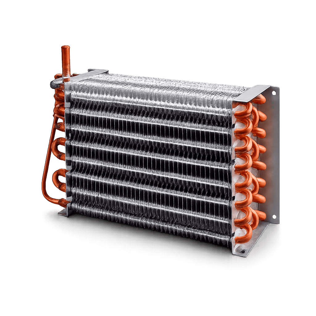
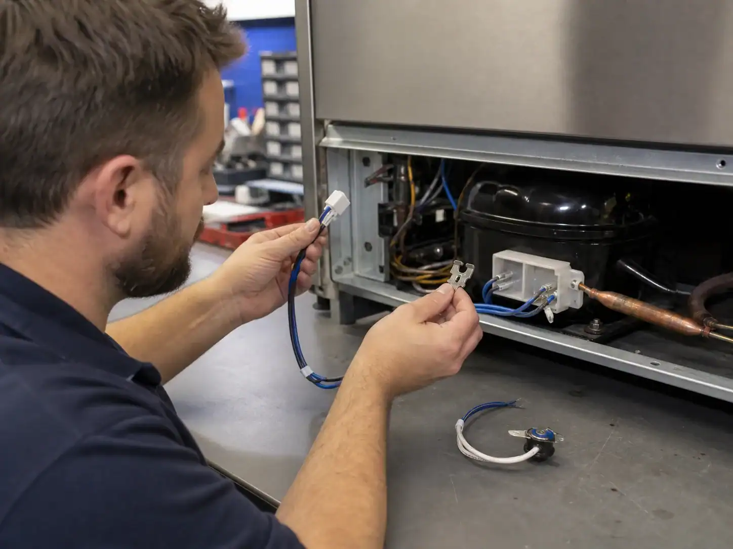
For the receiving inspection, check the part marking, body, connector, clip, wire length, mounting direction, and measured state or resistance at the defined test temperature. Keep the result with the coil and cabinet revision. If a substitute is proposed, document the technical comparison and require engineering approval before production or service use. A compatible-looking component is not a controlled alternate until the cabinet defrost cycle has been validated.
When the thermostat or sensor is supplied as part of a replacement coil, the supplier should identify the mounting operation and the inspection point. When it is supplied by the customer, the supplier should state the required clip, clearance, and installation datum. In both cases, the service instruction should explain how to verify the component after replacement. This prevents a correct part from becoming an incorrect system because it was clipped to a convenient but thermally different location.
Preserve the temperature evidence
When a field unit is returned for review, record the component temperature, electrical state, frost pattern, heater command, and cabinet condition together. A thermostat may appear to fail when it is actually in the wrong state because the coil never reached the expected temperature, the sensor lost contact, the control did not request defrost, or the heater did not respond. The evidence should show which condition was observed and which test separated the possibilities.
For an OEM program, retain the approved temperature curve or cut-in/cut-out range with the drawing. If the supplier proposes an alternate, compare the curve, tolerance, connector, mounting, environmental rating, and cabinet cycle. A change that looks small on the parts list can alter frost clearance, drain timing, and post-defrost pull-down. Keep service, quality, and procurement records tied to the same revision so the next replacement is selected from the approved configuration.
FAQ: refrigerator defrost thermostat
What is a refrigerator defrost thermostat?
It is a temperature-dependent component that enables, terminates, or protects a defrost circuit in a refrigerator. Some models use a mechanical thermostat; others use a thermistor and electronic control. The component’s role must be identified from the model schematic.
How does a defrost thermostat cause a warm refrigerator?
If the thermostat or sensor prevents the defrost heater from operating, frost can block the evaporator and airflow. If it fails to terminate the cycle, the heater can overheat or the control can enter a protective state. Both conditions can affect cabinet temperature.
Can I test a defrost thermostat with a multimeter?
A qualified technician can test it according to the model service procedure, at the specified temperatures and circuit state. A single room-temperature continuity reading is not enough to prove compatibility or failure.
Is a thermistor the same as a defrost thermostat?
No. A mechanical thermostat changes contact state; a thermistor changes resistance and reports temperature to a control. The control, connector, curve, mounting, and service procedure differ.
Why does the freezer work while the refrigerator is warm?
Ice can block evaporator airflow, or a fan, damper, vent, return path, sensor, or control can fail. Defrost thermostat failure is one possible cause, not the only cause.
Does the thermostat go on the coil or near the heater?
The location is model-specific. It may clip to a tube, fin, bracket, or another defined surface. Use the approved drawing or service manual; moving it changes the temperature it sees.
Does Domi automatically supply a defrost thermostat with a coil?
That scope should be confirmed for the project. A coil quotation may be for the heat-transfer component only. List heater, thermostat, thermistor, clips, harness, drain, cover, and other interfaces separately as included, customer-supplied, or subject to review.
What does an OEM need to send for compatibility review?
Send the model and part number, schematic, drawing revision, thermostat or sensor data, heater and coil geometry, mounting and connector details, refrigerant and operating conditions, frost and defrost requirements, test plan, volume, MOQ, packaging, and schedule.