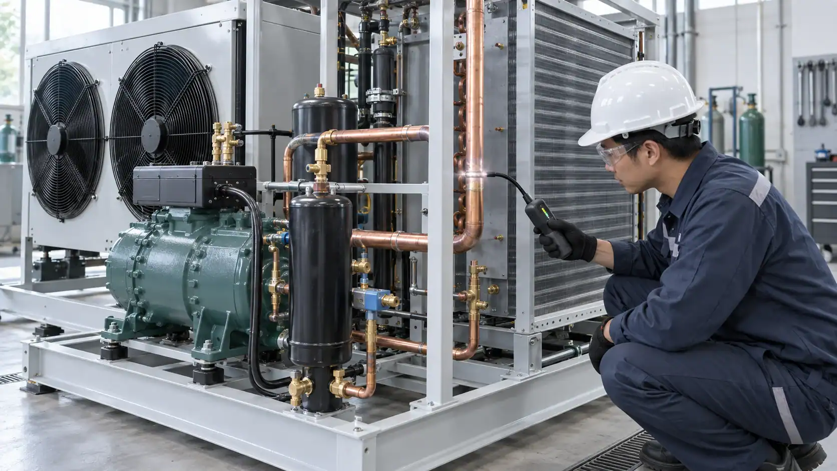
Refrigeration leak detection is a staged process: define the circuit, identify the refrigerant and operating condition, use a locating method, verify the repair with a suitable test, and keep evidence that another engineer can review. The right method depends on whether you need to find a local leak, confirm pressure integrity, measure leak flow, or monitor a machinery room continuously.
What refrigeration leak detection must prove
A leak test can answer several different questions, and each question needs different evidence. A handheld detector may help locate a refrigerant release near a joint. A pressure decay test can show that an isolated circuit is losing pressure, but it does not tell you where the opening is. A fixed sensor can warn that refrigerant concentration is rising in a room, but it usually cannot identify the failed component by itself.
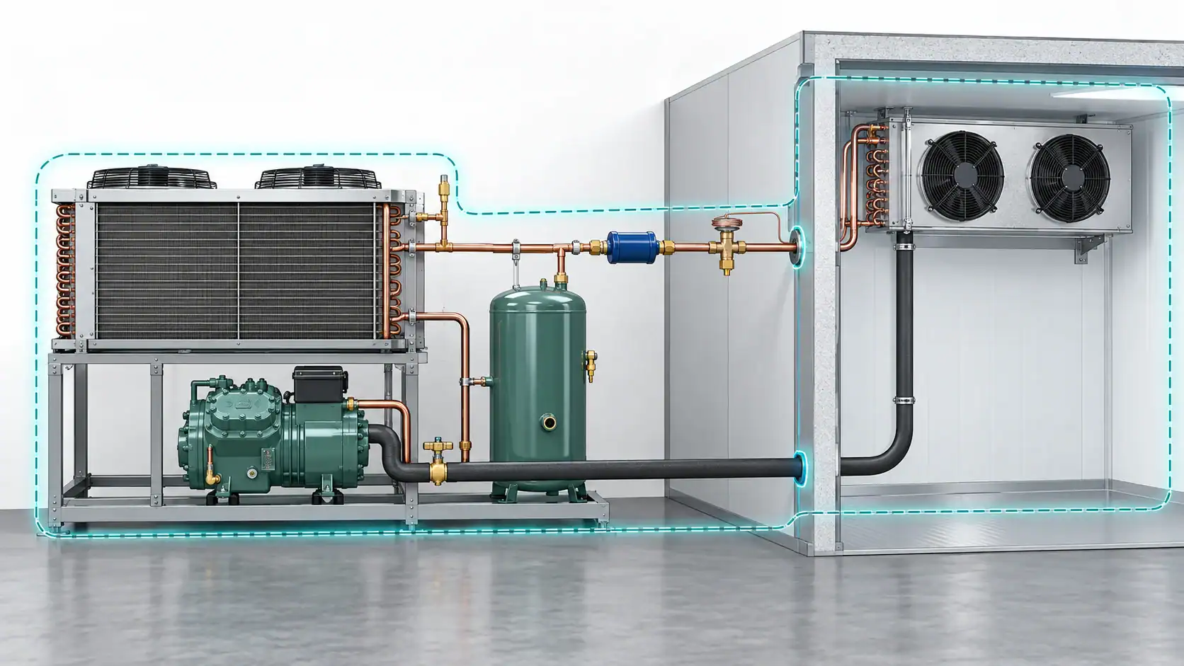
Before selecting a tool, write the test objective in one sentence. For example: “Locate a suspected leak at the evaporator outlet,” “verify a repaired coil before charging,” or “monitor a machinery room for a refrigerant release.” This prevents a common failure in refrigeration troubleshooting: using operating symptoms as proof of leak location.
The EPA Section 608 questions and answers describes several locating approaches, including ultrasonic, gas-imaging, bubble, and electronic methods. The same source explains that pressure or vacuum decay can indicate whether a circuit is leaking, while a separate locating method is needed to find the point of release.
Start with the system boundary and refrigerant
An accurate result begins with a defined boundary. Decide whether the test covers the complete system, one coil, a heat exchanger, a receiver, a line set, or a section between service valves. Record the isolation points so the result cannot later be mistaken for a test of a larger or smaller volume.
| Input to define | Why it changes the leak detection plan | Evidence to capture |
|---|---|---|
| Refrigerant or test gas | Affects detector compatibility, safety controls, and allowable test method | Refrigerant name, blend if relevant, and test medium |
| Circuit boundary | Determines which components are included and how a pressure loss is interpreted | Marked drawing or valve isolation record |
| Operating condition | Temperature and pressure change detector response and test stability | Test temperature, pressure, and equipment state |
| Test objective | Separates locating, verification, monitoring, and measurement tasks | One sentence test objective |
| Access condition | Insulation, airflow, oil film, and restricted joints can hide a release | Access notes and inspected locations |
| Acceptance rule | A pass needs a defined limit, duration, or required record | Customer or project acceptance criteria |
For a coil or assembly RFQ, also identify the tube material, header arrangement, brazed or welded joints, service ports, circuiting, design pressure, and connection orientation. These details help the supplier understand which joints are accessible during production testing and which areas will be difficult to inspect after installation.
Inspection versus verification testing
Inspection and verification are related, but they are not the same activity. Inspection looks for a release at a specific location. Verification tests whether a defined component or circuit meets an integrity requirement after assembly or repair. A credible work instruction states which one is being performed.
The EPA stationary refrigeration leak repair requirements and its related guidance use initial and follow-up verification concepts for covered equipment. Project teams should confirm the rules that apply to their refrigerant, equipment category, and jurisdiction. A supplier article should not replace the responsible engineer’s regulatory review.
| Test activity | Main question | Typical output | Limitation |
|---|---|---|---|
| Visual and joint inspection | Is there a visible defect, oil trace, corrosion point, or damaged connection? | Location photos and inspection notes | A clean surface does not prove tightness |
| Bubble solution | Can a local pressurized joint show visible bubble formation? | Marked leak location and photo | Surface condition, airflow, and access affect sensitivity |
| Electronic detection | Is refrigerant concentration near the probe above the detector response threshold? | Detector reading, location, and conditions | Needs the correct sensor and controlled scanning technique |
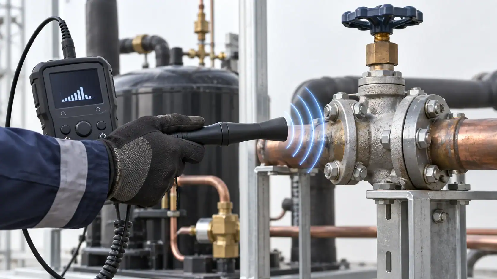
| Ultrasonic detection | Is turbulent gas flow creating an ultrasonic signature near the suspected point? | Audio or instrument result with location | Background noise and pressure difference affect response |
| Pressure decay | Does an isolated circuit lose pressure during a defined hold? | Start and end pressure, time, temperature | Indicates loss but does not locate the leak |
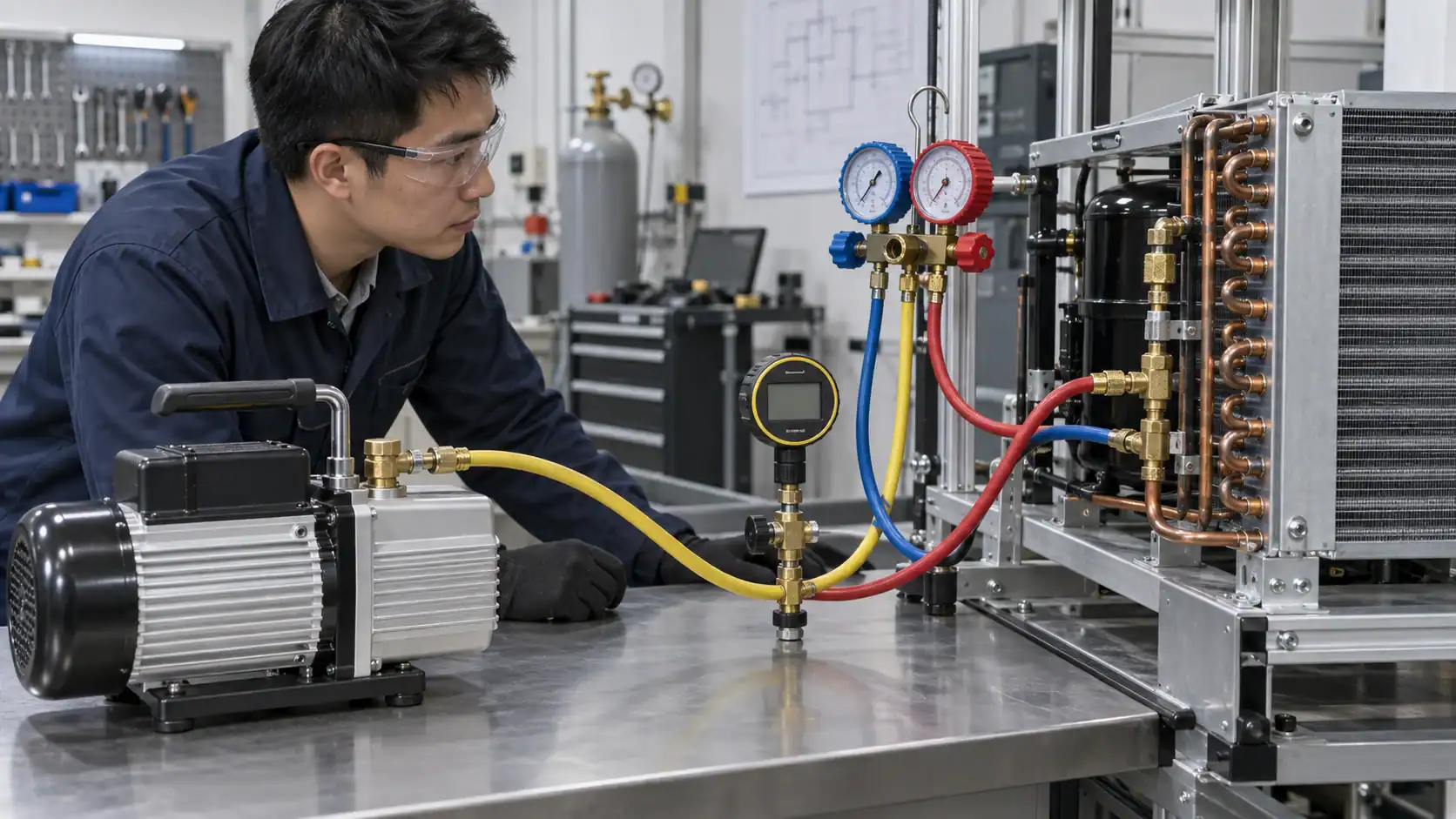
| Vacuum hold | Does an evacuated circuit remain stable for the defined period? | Vacuum level, time, and temperature | Moisture, temperature change, or trapped volume can mislead |
| Tracer gas or imaging | Can a sensitive instrument reveal a small release under controlled conditions? | Instrument result and confirmed location | Requires compatible gas, equipment, training, and safety controls |
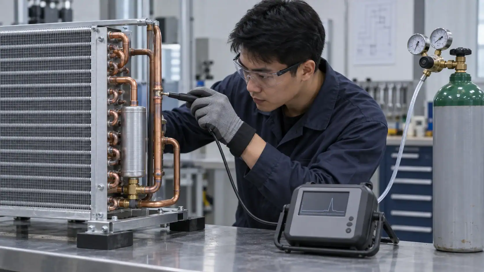
No single method is automatically best for every system. A service team may use an electronic detector to narrow the search, bubble solution to confirm a joint, and a pressure or vacuum test to verify the isolated assembly. The sequence should be written into the work instruction before testing starts.
How to sequence a refrigeration leak test
1. Stabilize and make the test safe
Confirm the refrigerant, isolate the equipment, control ignition and ventilation risks where relevant, and use the required personal protective equipment. Do not introduce a test gas or open a circuit until the procedure identifies the connection points, pressure limit, and release path.
2. Inspect the accessible points first
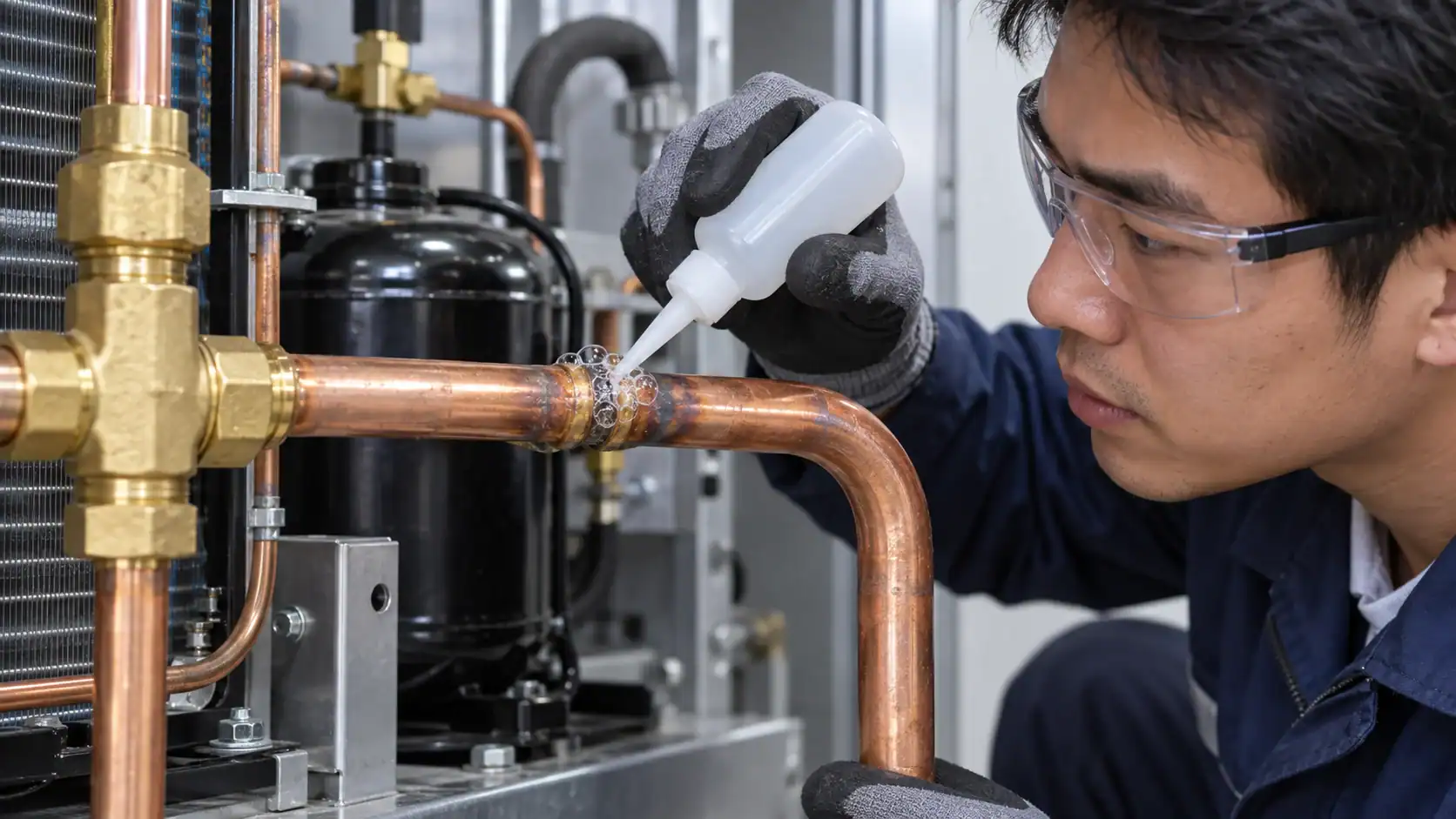
Look at brazed joints, return bends, headers, service ports, valve stems, flanges, vibration points, and areas with oil residue or corrosion. On a coil, check the connection between the circuit tubing and header, not only the large visible tube surfaces. Photograph the suspected location before cleaning if the record needs to show the original condition.
3. Use a locating method that matches the condition
An electronic detector can be useful around service connections and enclosed equipment when the probe can reach the air around the suspected point. Ultrasonic tools can help when a pressure differential creates detectable flow. Bubble solution is useful for a visible confirmation on an accessible pressurized joint. A tracer gas or imaging method may be considered when the release is small, intermittent, or difficult to access.

4. Verify the defined assembly
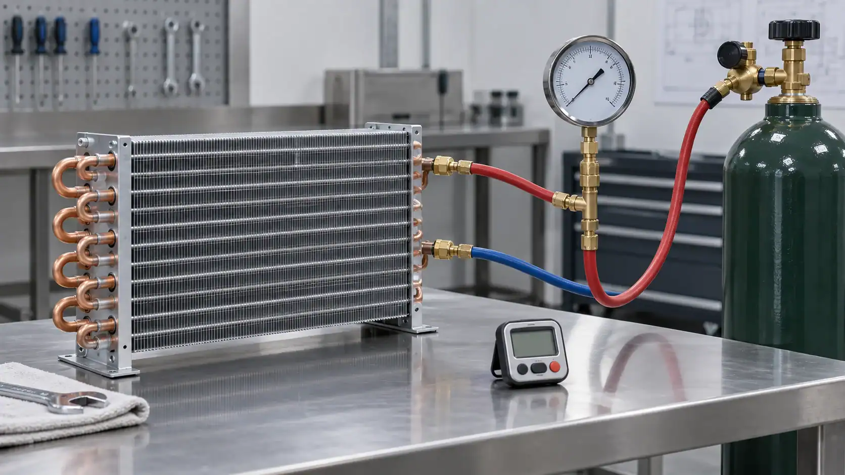
If the component has been repaired or newly fabricated, isolate the agreed boundary and perform the required pressure or vacuum verification. Record the test medium, start condition, hold period, temperature, and end condition. If the acceptance rule requires a leak rate or a particular standard, record the method and instrument used rather than writing only “passed.”
5. Recheck after the condition changes
Temperature changes, vibration, valve movement, and reassembly can change the result. If the work instruction requires an initial and follow-up check, keep both records. The EPA recordkeeping and reporting guidance is a useful reference for why dates, equipment identity, actions, and verification evidence should remain traceable.
Which refrigeration leak detection method fits the job?
Selection should follow the buyer’s risk and evidence need. A small OEM coil that must be released for shipment has a different test record from a supermarket machinery room that needs continuous warning. The table below is a starting point for the engineering discussion, not a substitute for the project standard.
| Buyer situation | First method to consider | Add a second method when | Record for supplier or quality review |
|---|---|---|---|
| Suspected accessible joint | Bubble solution or electronic detector | The signal is intermittent or the surface is contaminated | Location, detector or solution, conditions, photo |
| Suspected small release | Electronic, ultrasonic, tracer gas, or imaging method | The detector response needs confirmation | Instrument identity, settings, location, result |
| New coil before shipment | Defined pressure or vacuum verification | The acceptance rule needs a local leak location | Boundary, medium, pressure or vacuum, time, temperature |
| Repaired system | Local locating method followed by verification | A follow-up check is required after operation | Repair point, initial check, follow-up check |
| Machinery room | Fixed gas detection and alarm design | A release must be located at equipment level | Sensor location, alarm path, calibration or service record |
| Disputed field result | Repeatable controlled test with independent review | The first test had poor access or unstable temperature | Original record, repeat record, root cause, disposition |
Where refrigeration systems and coils commonly leak
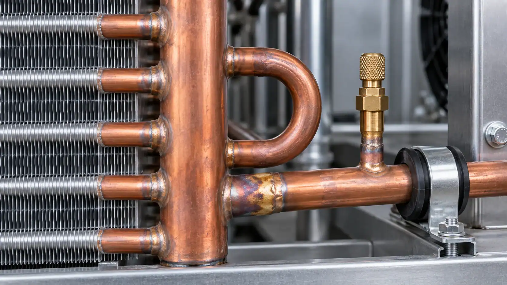
The most useful inspection map follows construction and movement. Look for joints that see vibration, thermal cycling, pressure cycling, rubbing, corrosion, or repeated service access. A leak location should be named precisely enough that another person can find it without guessing.
| Area to inspect | What can create a leak path | What the record should identify |
|---|---|---|
| Tube-to-header connection | Brazing defect, thermal stress, corrosion, or incomplete wetting | Header side, circuit, tube position, and joint photo |
| Return bend | Vibration, forming damage, or rubbing against a support | Bend location and support condition |
| Service port or valve stem | Cap, core, gasket, or packing issue | Port identity and cap or core condition |
| Flange or removable joint | Gasket damage, uneven tightening, or surface defect | Joint faces, gasket, torque or assembly note |
| Line support and vibration point | Rubbing, fatigue, or unsupported tubing | Contact point, support, and movement condition |
| Corroded or contaminated surface | Wall loss, pitting, oil film, or cleaning residue | Surface preparation and before or after photos |
The Domi evaporator coil leak diagnosis guide covers coil-specific diagnosis and replacement decisions in more detail. Use it when the system-level inspection has narrowed the suspected release to an evaporator coil.
When continuous refrigerant monitoring is appropriate
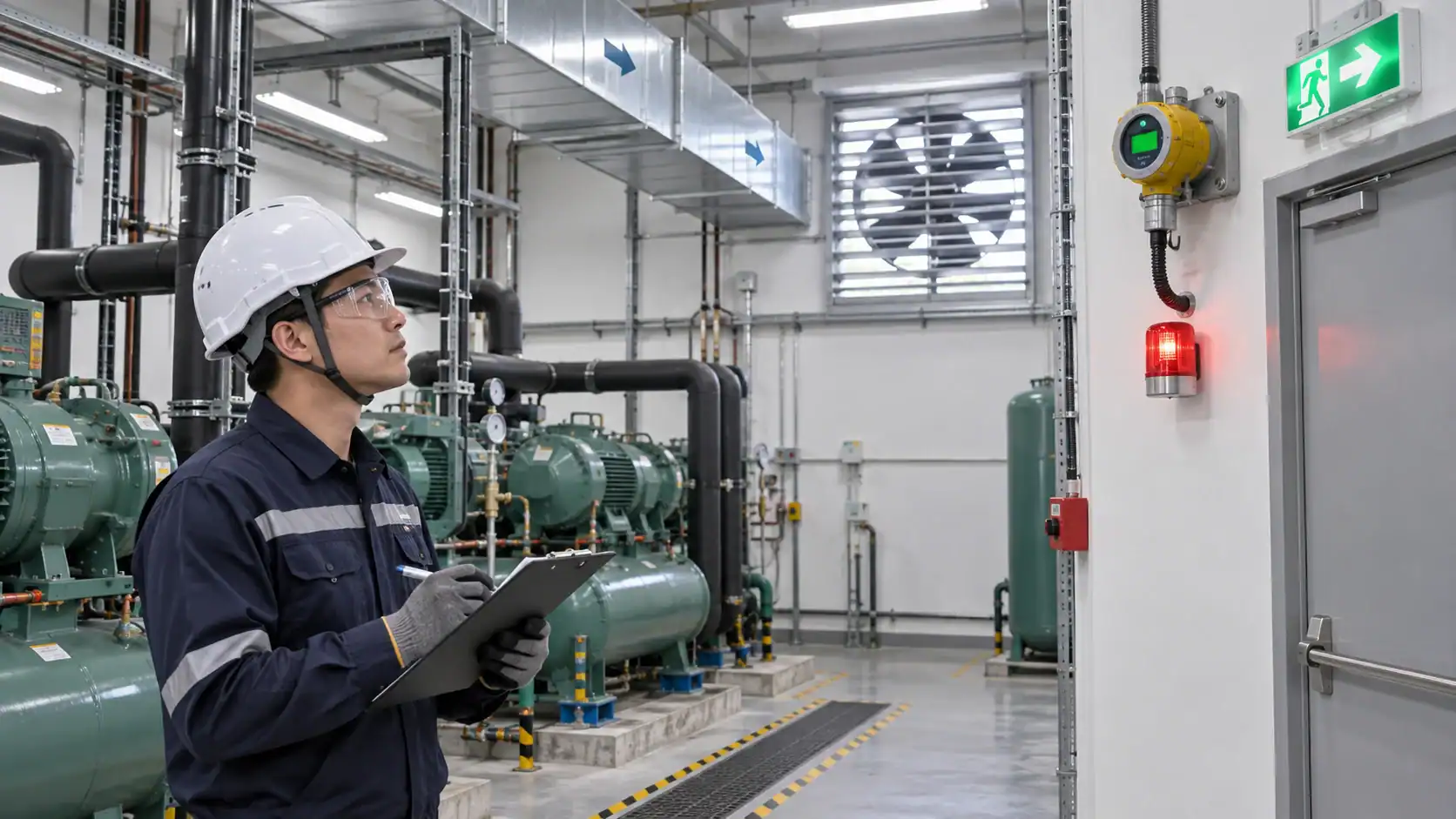
Fixed refrigerant detection is a facility safety and monitoring decision. It is useful when the equipment room, cold room, or enclosed space needs an alarm path even when no technician is present. Sensor location, airflow, refrigerant density, ventilation, alarm response, and maintenance access all matter.
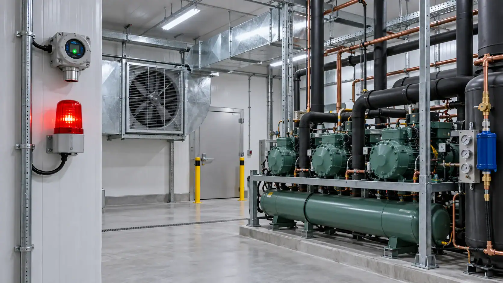
The Danfoss gas detection sensor reference and Copeland refrigerant leak detector reference show why the sensor type and installation context should be specified. Do not select a fixed sensor only because it has a convenient output. Confirm the refrigerant, expected concentration range, response requirement, alarm routing, and service plan.
| Monitoring question | Information needed before selection | Why the buyer should care |
|---|---|---|
| Where could refrigerant collect? | Room geometry, airflow, equipment position, and refrigerant properties | Sensor placement affects the chance of early detection |
| What response is required? | Local alarm, remote signal, ventilation interlock, or shutdown sequence | The detector is part of a response system, not an isolated device |
| How will it be maintained? | Calibration, replacement, access, and service interval | A sensor without a maintenance path can create false confidence |
| What evidence is needed? | Commissioning record, alarm test, and service history | Safety and quality teams need traceable verification |
| What changes for the refrigerant? | Refrigerant classification, concentration limits, and sensor compatibility | The same sensor arrangement may not suit every refrigerant |
For A2L and other safety-sensitive systems, have the responsible engineer confirm the applicable code, equipment classification, ventilation, ignition control, detection, and emergency response requirements. This article gives a planning framework and does not approve an installation.
What to record after the test
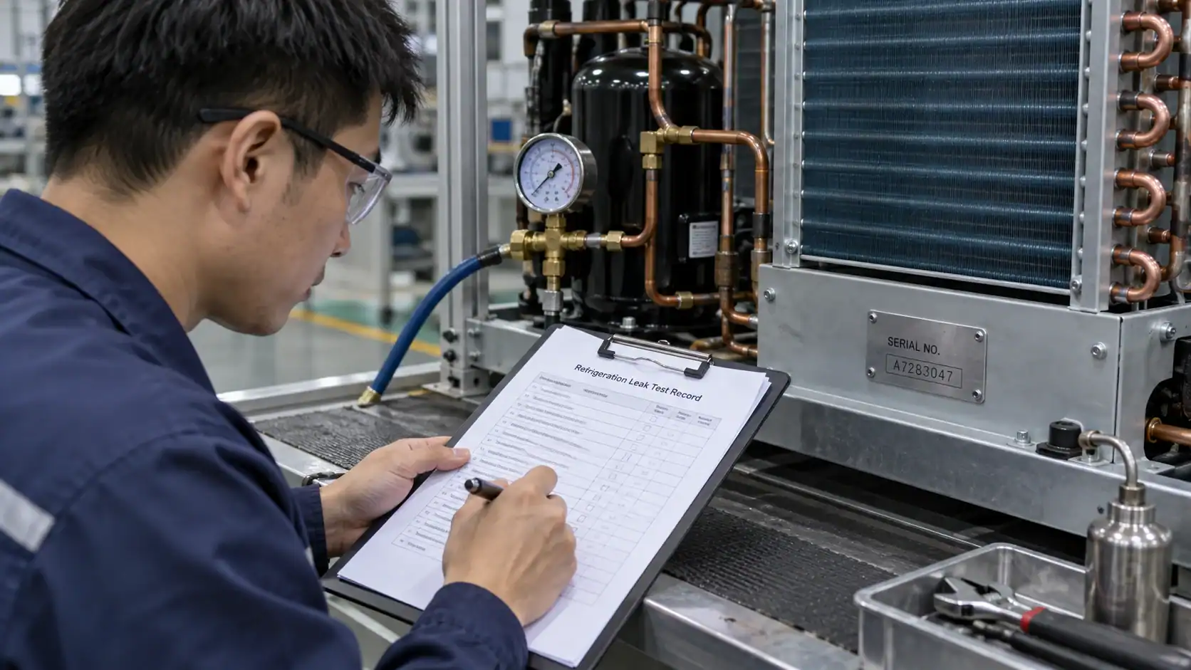
A test record should allow a reviewer to understand what was tested, how it was tested, what the instrument saw, and what happened next. A single “OK” line is hard to audit and difficult to compare with a future result.
| Record field | Minimum useful detail |
|---|---|
| Equipment identity | Model, serial or batch reference, assembly drawing, and circuit identity |
| Test boundary | Components included, isolation points, and excluded items |
| Refrigerant or test medium | Name, condition, and source or cylinder reference where required |
| Instrument | Detector, gauge, vacuum instrument, imaging tool, or test rig identity |
| Environmental condition | Test temperature, airflow, access condition, and time |
| Procedure | Method, sequence, hold period, and operator instructions followed |
| Result | Reading or observation, location, acceptance rule, and pass or fail disposition |
| Corrective action | Repair, retest, replacement, concession, or escalation |
| Approval | Operator, reviewer, date, and linked photos or files |
If a pressure or vacuum result is being compared over time, record temperature with the reading. A pressure change without a temperature context can be misread as a leak. The ASHRAE handbook refrigeration reference and ASHRAE standards and scopes are useful starting points when the project requires a more formal measurement framework.
Troubleshooting mistakes that weaken leak evidence
Treating low cooling capacity as leak location
Low capacity, high superheat, poor subcooling, frost patterns, and compressor behavior can point to several system conditions. They can justify an inspection, but they do not identify a failed joint. The Copeland troubleshooting fundamentals guide is useful for separating operating symptoms from a confirmed leak location.
Testing a larger boundary than the suspected component
If the whole circuit is tested when only one coil is suspected, the result may show a problem without helping the repair team. Isolate the smallest practical boundary, record it, and then use a locating method at the component level.
Writing down a result without the method
“Leak test passed” is incomplete. A buyer needs the method, test medium, pressure or vacuum condition, hold time, temperature, instrument, and acceptance criterion. Without those fields, the result cannot be compared to another supplier’s report.
Ignoring access and surface condition
Air movement, oil film, insulation, corrosion, and cleaning chemicals can affect a detector or bubble solution. Note the condition and repeat the check after preparation when the procedure requires it.
Choosing a detector before choosing the response
Fixed monitoring, local repair, shipment release, and regulatory verification are different outcomes. Start with the response and evidence requirement, then select the instrument and procedure.
OEM RFQ checklist for refrigeration leak detection
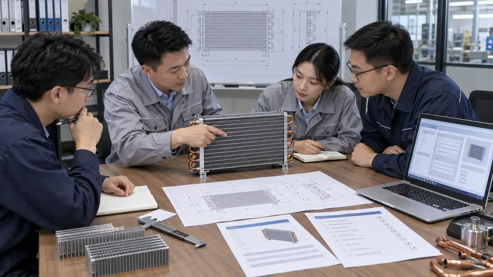
An RFQ is easier to review when the buyer sends the technical inputs together. The Domi testing lab page and custom coil fabrication page provide useful starting points for a technical request, while the supplier still needs the project-specific drawing and acceptance rule.
| RFQ input | Example of a useful buyer instruction |
|---|---|
| Product and application | Evaporator coil, condenser coil, heat exchanger, rack, cold room, or process system |
| Refrigerant | Refrigerant name, blend, charge context, and any safety classification |
| Geometry | Drawing, tube and header sizes, circuiting, connections, and service access |
| Operating data | Design pressure, operating pressure, temperature range, ambient condition, and airflow |
| Test objective | Locate a suspected leak, verify a new assembly, verify a repair, or monitor a room |
| Test method | Required method or request for supplier recommendation with justification |
| Acceptance rule | Hold period, allowable loss, leak rate, detector response, or customer standard |
| Test evidence | Photos, gauge records, instrument identity, serial traceability, and signed report |
| Delivery need | Sample quantity, production quantity, packaging, lead time target, and inspection release |
If the buyer has a drawing, sample, failed part, or existing test record, include it with the inquiry. A supplier can usually give a more useful feasibility response when the leak location, refrigerant, pressure, temperature, and required report are visible at the start.
When leak detection is part of a coil RFQ
For a custom refrigeration coil or heat exchanger, leak detection should be specified together with the assembly boundary, operating condition, test method, acceptance rule, and report format. Share the drawing, refrigerant, design pressure, circuiting, connection details, quantity, and sample or failed-part photos. Domi can then review which information is available for a technical quotation and which test details need confirmation before production planning.
Frequently asked questions
What is refrigeration leak detection?
Refrigeration leak detection is the process of finding or verifying a refrigerant release in a defined circuit or equipment boundary. It can include visual inspection, bubble solution, electronic detection, ultrasonic detection, pressure or vacuum verification, tracer gas, imaging, and fixed room monitoring. The method should match the test objective and the evidence required.
Which method is best for a refrigeration leak?
The best method depends on whether you need to locate a release, verify a repaired assembly, measure leak flow, or monitor a room. An electronic detector or bubble solution may help locate an accessible joint. A pressure or vacuum test can verify a defined boundary but normally cannot locate the release by itself. A project may need more than one method.
Can a pressure decay test locate a leak?
No. Pressure decay can show that the defined boundary is losing pressure during the test condition. It does not identify the failed joint. Pair it with an appropriate locating method and record the test boundary, starting condition, hold time, temperature, and result.
How do I test an evaporator coil for leaks?
Start by identifying the coil circuit, connections, headers, return bends, and service points. Inspect accessible joints, choose a compatible locating method, and then apply the specified pressure or vacuum verification to the isolated coil or assembly. Record the circuit identity, test condition, instrument, location, acceptance rule, and photos. Use the evaporator coil leak diagnosis guide for coil-specific troubleshooting context.
How often should a refrigeration system be checked for leaks?
The answer depends on the refrigerant, equipment category, applicable regulation, service history, risk, and owner’s maintenance program. Use the responsible engineer’s compliance schedule and manufacturer instructions. Increase attention after a repair, abnormal operating symptom, vibration event, corrosion finding, or repeated refrigerant loss.
What should an OEM include in a leak test report?
Include equipment identity, drawing or serial reference, test boundary, refrigerant or test medium, instrument identity, environmental condition, method, pressure or vacuum data, hold time, acceptance rule, result, photos, corrective action, and approval. This lets the buyer compare a supplier result with the original requirement and trace the decision later.