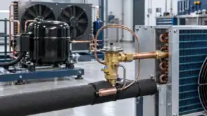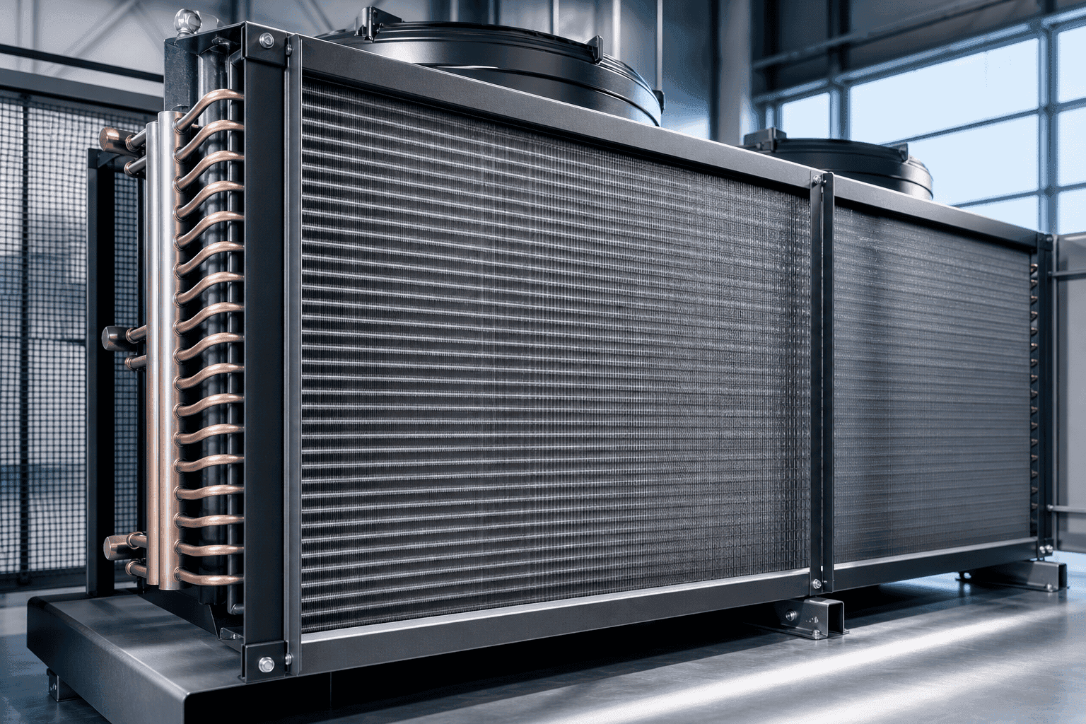
Condenser fins increase the air-side surface available for rejecting heat from the refrigerant tubes. Their spacing, material, thickness, contact with the tubes, surface condition, airflow and cleaning access must be considered together. A fin design that looks dense or large is not automatically the right design for a commercial refrigeration system.
Condenser fins are easy to see, so they often become the first part that buyers inspect when a commercial refrigerator runs hot. Bent fins, dust, grease, salt, corrosion, and damaged edges are visible. The harder questions are less visible: what fin spacing was used, which airflow was assumed, what heat-rejection duty was required, whether the fan can overcome the air-side pressure drop, and whether the surface matches the equipment environment.
This guide focuses on commercial condenser fin design and replacement decisions. It does not repeat the general condenser coil failure and maintenance guide, and it does not treat a hand tool or a visual inspection as a complete engineering diagnosis. The purpose is to help OEM buyers, engineers, distributors, and service teams describe the fin-related requirements in a quotation or design review.
The target page, commercial refrigeration solutions, covers the wider component and application path. A condenser is a system component, and the fins must be evaluated with the tubes, circuiting, header, fan, shroud, grille, cabinet, controls, ambient, refrigerant, coating, and service method.
What do condenser fins do?
Condenser fins create more air-side surface area than the tube wall alone. Heat moves from the refrigerant through the tube wall and tube-to-fin contact into the fin material, then into the air moving across the surface. The fins do not create heat rejection by themselves. They are one part of the thermal resistance chain, and their value depends on contact, airflow, temperature difference, material, geometry, and cleanliness.
If the fin surface is blocked, bent, corroded, or poorly distributed, the effective heat-transfer area falls. If the fin pack is too restrictive, the fan may not deliver the intended airflow. If the fin spacing is too open for the available cabinet, the coil may need a larger face or deeper construction. The correct design balances thermal capacity with air-side pressure drop and operating conditions.
Fin and tube work as one surface
The tube carries the refrigerant and the fin carries heat into the air. Mechanical expansion, brazing, bonding, or another joining method must maintain useful contact over the operating temperature range. A loose contact can increase thermal resistance. A damaged fin pack can create local bypass or airflow imbalance. A coating or surface treatment can change thickness, roughness, contact, and corrosion response.
Condenser fins are not the same as evaporator fins
Both may use a finned-tube surface, but the operating environment can differ. A condenser often sees warmer air, dust, grease, rain, salt, and outdoor exposure. An evaporator may see condensation, frost, drain water, and lower surface temperature. Fin spacing and material selection should follow the side of the system and the maintenance condition.
Air side versus refrigerant side
Fin design controls an important part of the air side, but it does not replace circuiting or refrigerant review. A coil with excellent air-side area can still perform poorly if refrigerant distribution, pressure, subcooling, header, or compressor conditions are wrong. The EPA overview of advanced refrigeration technologies explains how commercial refrigeration architectures vary, which is why the fin discussion should start with the system context.
Fin spacing and air-side pressure drop
Fin spacing is the distance between adjacent fins. It influences available area, air passages, pressure drop, fouling tolerance, surface wetting, cleaning, and cabinet depth. Close spacing can provide more area in a compact face. Wider spacing can improve air passage and cleanability. Neither is a universal rule.
The right spacing depends on airflow, dust, grease, moisture, salt, service frequency, fan curve, face area, row depth, and the required heat rejection. A dense coil in a clean factory room may behave differently from a similar coil in a restaurant kitchen. A condenser located behind a grille may operate with more resistance than the open-coil rating suggests.
| Fin spacing condition | Potential benefit | Design or maintenance risk |
|---|---|---|
| Close spacing | More surface in a small face | Higher air pressure drop, faster blockage, harder cleaning |
| Moderate spacing | Balance of area and airflow | Still needs environment and fan review |
| Wide spacing | Better passage and cleanability | More face area or depth may be required |
| Variable or special pattern | Can address local airflow or packaging | More complex manufacturing and comparison |
| Damaged or collapsed fins | None, reduces free area | Local blockage, bypass and poor heat rejection |
The table describes tradeoffs rather than recommending a specific pitch. A supplier should state the spacing in the quotation and relate it to the heat-rejection rating and air-side pressure drop.
Face velocity and fin pack depth
Average face velocity is useful for screening, but it does not show how air moves through a deep fin pack. More rows increase surface, but they can also increase pressure drop and create a less accessible surface. If the fan cannot provide the required airflow at the actual system resistance, the condenser may run at a higher condensing pressure even though the fin area looks sufficient.
Request airflow, face area, fin pitch, row count, depth, and pressure drop together. If the fan is part of the assembly, request the fan curve or identify the fan model. If the grille or shroud is not included, say so. The fin design should not be rated in isolation from the air path that the equipment will use.
Louver and surface patterns
Some fin designs use louvers, offset patterns, or other surface features to improve air-side heat transfer. Such features can also change pressure drop, dirt retention, cleaning method, and manufacturing tolerance. If a special pattern is proposed, ask why it is needed for the application and what performance condition supports it. Avoid using a pattern name as a substitute for a rating.
Materials and tube-to-fin contact
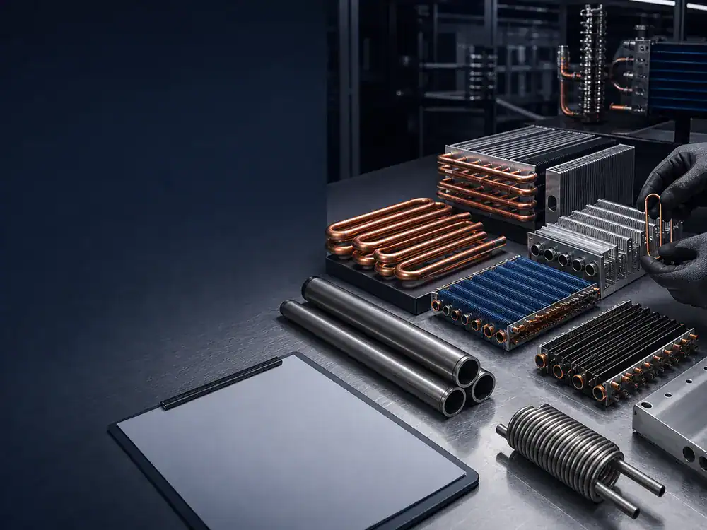
Fin material should be selected with heat transfer, corrosion, joining, coating, weight, cleaning, and cost in mind. Aluminum and copper are common in many coil families, but the right material depends on the system and environment. A material name alone does not define thickness, temper, surface treatment, contact method, or compatibility.
Tube expansion and contact
A fin pack needs reliable contact with the tubes across the intended operating range. Tube expansion, mechanical fit, brazing, bonding, or other methods have different manufacturing and inspection considerations. The buyer should ask what contact method is used and how the finished coil is checked, especially when the fin design or tube pattern changes.
Corrosion exposure
Restaurant grease, steam, salt, detergents, humidity, dust, and wet-dry cycles can affect fins and tube-to-fin contact. A corrosion-resistant request should describe the exposure and cleaning practice. Do not promise a service life or corrosion class without a verified material, coating, test, or project record.
The EPA GreenChill program provides useful background on commercial refrigeration equipment and environmental practices. It does not establish a condenser-fin coating rating. Keep refrigerant, emissions, coating, material, and heat-transfer claims separate in the specification.
Coating and thickness
A coating can affect fin thickness, surface condition, heat transfer, contact, masking, joints, and cleaning. If coating is being considered, state whether it covers the fin face, tube, header, bracket, or complete assembly. Confirm the masking of connections and the inspection of coverage. A coated condenser fins design should be compared at the same duty and airflow condition as a bare-metal proposal.
Fouling, grease and cleaning access
Fouling reduces free area and can increase air-side pressure drop. Dust blocks passages. Grease can create a sticky layer that captures dust. Salt and moisture can accelerate corrosion. Bent edges reduce open area. A design that performs on a clean bench may lose capacity in service if the environment and maintenance interval are ignored.
The equipment team should identify the expected cleaning method, frequency, chemical, water pressure, rinse, drying, and access. If the condenser is behind a grille, include the grille and removal path. If the fan must be removed before cleaning, state that in the service procedure. The correct fin spacing is partly a maintenance decision.
Cleaning tools and fin damage
Fin combs, soft brushes, vacuum tools, low-pressure water, and other methods may be used according to the equipment instructions. A sharp or uncontrolled tool can fold the fins and reduce the air path. A buyer should not assume that a general tool is suitable for every fin pitch or coating. Record the approved maintenance method with the equipment.
Grille, shroud and bypass
A condenser can lose performance through bypass around the fin pack or through a blocked grille. A shroud can improve fan coverage but can also add resistance if it is poorly fitted. The fin design review should include opening area, seal, fan location, shroud, grille, and service clearance. If a replacement changes the depth or face, the air path may need a new review.
Fin design for different commercial applications
Commercial refrigeration equipment varies in location and duty. A beverage cooler may have a small condenser with a tight cabinet path. A prep table may see kitchen grease and moisture. A remote condenser may see weather and a larger fan. An ice machine may operate through repeated cycles and need a compact service path. A replacement distributor may need multiple fin variants with controlled drawings.
| Application | Fin design question | Additional information |
|---|---|---|
| Beverage cooler | Can the compact fin pack reject heat through the cabinet grille? | Fan, grille, ambient, cabinet clearances |
| Restaurant equipment | Can the surface be cleaned and resist the stated exposure? | Grease, moisture, chemical and cleaning schedule |
| Ice machine | Does the condenser support repeated cycles and service access? | Cycle, ambient, fan, model, maintenance path |
| Supermarket or remote unit | Can the condenser meet peak ambient and weather exposure? | Heat rejection, outdoor condition, airflow, piping |
| Replacement program | Will the fin design remain interchangeable across revisions? | Drawings, dimensions, SKU, packaging and forecast |
Customer-facing and noise-sensitive areas
Fin spacing and air pressure drop can affect fan speed and sound. If the condenser is near customers or staff, state the target and the measurement location. A change in fin pitch should be reviewed with the fan and shroud. A quieter fin pack is not guaranteed by a larger surface; the complete air system controls the result.
Condenser fin design and heat-rejection rating
A condenser fin design should be rated at a defined heat rejection, refrigerant, condensing condition, entering-air condition, airflow, and pressure-drop basis. If the system has a subcooling section, state whether it is included. If the coil is rated clean, state how maintenance or fouling is handled in the operating plan.
The AHRI 410 standard is a useful reference for certain air-cooling and air-heating coils, but its scope lists exclusions that include refrigerant condenser coils. That is a reason to name the actual rating procedure instead of placing an AHRI number in a product description without checking scope.
What a supplier rating should show
Ask for heat rejection, refrigerant, condensing condition, entering air, airflow, air pressure drop, subcooling if applicable, fin pitch, rows, face dimensions, depth, materials, connections, and fan scope. If the proposal uses a different test or calculation basis, request a deviation note. A clear data sheet supports a fair comparison.
Thermal and air-side balance
A fin design may add surface area but increase air pressure drop. The fan may respond with higher speed, sound, or power. A design may reduce air velocity but require a larger cabinet. The supplier should explain the balance and identify any assumption that the equipment designer must confirm.
Replacement condenser fins review
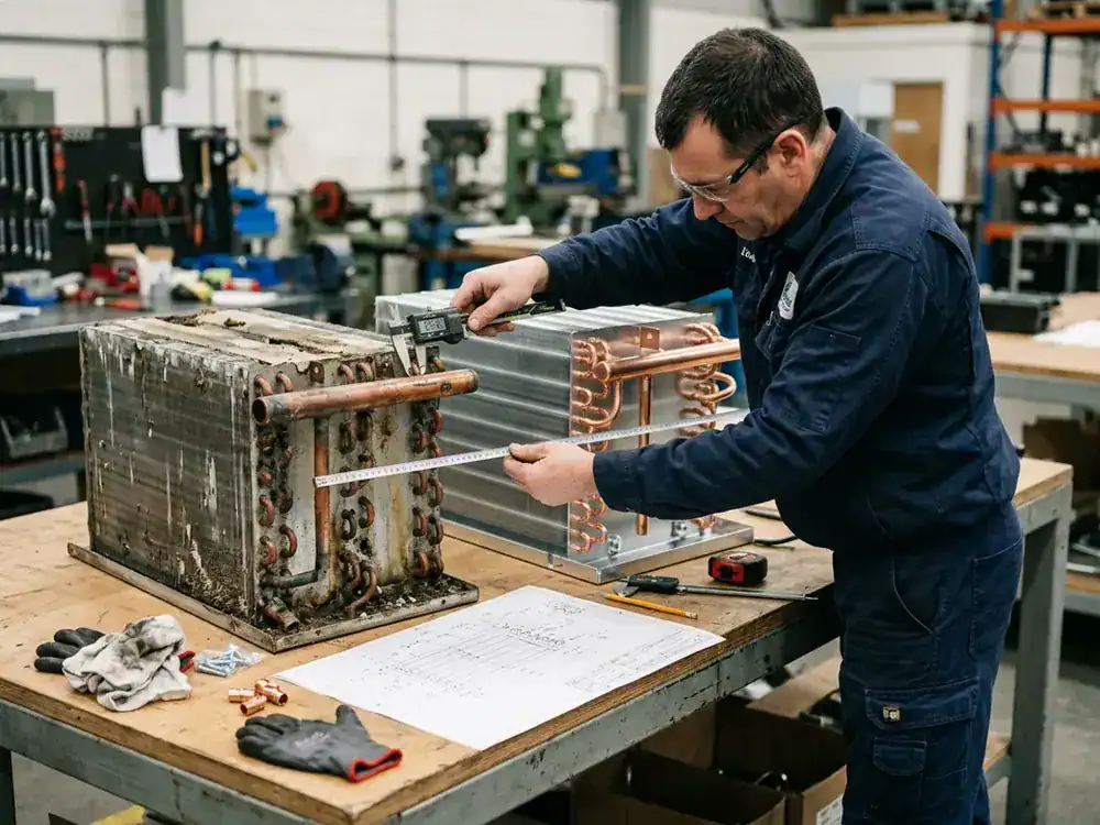
When a replacement coil has damaged condenser fins, determine whether the fins can be restored or the whole coil should be replaced. A fin comb may correct limited bending, but it cannot repair corrosion, a tube leak, lost tube-to-fin contact, missing sections, or a structural failure. The service decision belongs to a qualified technician or equipment owner.
For a new replacement, measure the face, depth, fin pitch if possible, row count, tube pattern, header, connections, brackets, fan, grille, and clearances. Photograph the fins before cleaning. Mark the airflow direction and the failure area. If the original fin design was too restrictive or poorly protected, tell the supplier rather than requesting an identical copy.
Visible damage is not the whole diagnosis
Bent fins may be the result of cleaning, installation, shipping, impact, or a fan tool. Corrosion can be associated with water, salt, chemicals, or a coating failure. Dust can indicate a service schedule problem or an airflow filter issue. Use the visible pattern and operating data together. Do not claim the fins caused a high-pressure alarm until the fan, grille, refrigerant, ambient, and control conditions are checked.
Packaging and installation
Condenser fins are vulnerable during handling. Packaging should protect the face, headers, connections, brackets, and coated surface. The buyer should state the transport route and destination if the part is exported or distributed. Installation instructions should explain lifting, connection protection, clearance, fan direction, and fin inspection.
RFQ checklist for condenser fins
The RFQ should be specific enough for a supplier to state fin design and air-side assumptions. The ASHRAE standards and guidelines resource may help identify the broader project references. It does not replace the equipment drawing or the component data sheet.
| RFQ field | What to provide | Why it matters |
|---|---|---|
| Application | Equipment type, location, ambient and duty | Sets environment and rating basis |
| Air side | Fan, airflow, grille, shroud, face area, pressure limit | Sets fin and air-path review |
| Refrigerant side | Refrigerant, condensing condition, pressure, subcooling | Sets heat rejection and circuit review |
| Fin construction | Pitch, material, thickness, pattern, coating | Sets area, fouling, corrosion and cleaning discussion |
| Mechanical | Height, width, depth, rows, connections, brackets | Controls fit and replacement feasibility |
| Service | Cleaning, chemicals, access, inspection, packaging | Controls field condition and damage risk |
Ask for the open items
If the fan is not selected, say so. If the ambient is uncertain, give a range. If the coating is under discussion, describe the exposure. If the final refrigerant is not released, list the candidate and pressure requirements. The supplier can then identify what can be screened and what requires engineering confirmation.
Quality checks for a finned condenser
Quality checks may include material and thickness, fin pitch, fin damage, tube-to-fin contact, tube pattern, overall dimensions, circuiting, connection positions, joint quality, pressure or leak testing, coating coverage, brackets, and packaging. The required records depend on the project. State the inspection plan instead of assuming a standard package.
A sample can prove fit-up while leaving thermal performance open. A thermal test can show capacity while leaving field cleanability open. Use a staged approval and keep the drawing, fin design, data sheet, test, and change record aligned.
Fin design change control
Changes to fin pitch, pattern, material, coating, tube contact, row count, depth, header, or connection can affect rating and service. A revision number should identify the change. Procurement and service should receive the same revision. If multiple equipment variants share a fin family, show which dimensions and ratings are common and which are not.

Fin pack design in drawings and validation
The fin pack should be visible in the design record. Show fin pitch, material, thickness if controlled, tube pattern, rows, total depth, face dimensions, airflow direction, headers, connections, brackets, and any coating or treatment. If the fin pattern is proprietary, the drawing can use a controlled part or specification reference, but the purchase description must still identify the performance and material requirements.
Dimension the condition that matters
Fin pitch can be described in different ways, and drawings can become ambiguous if the reference is not clear. Use the engineering convention used by the equipment and supplier, and identify the measurement basis. Show the effective face area rather than only the frame size if the frame has blocked edges. Mark the area occupied by headers, supports, fan hubs, and bypass zones when the air-side rating depends on them.
Show the air path
The drawing should identify entering and leaving air sides, fan position, grille, shroud, baffle, and any filter. This helps the engineer understand whether the coil is blow-through or draw-through and whether the fin pack sees a uniform stream. If the condenser can be installed in more than one orientation, show the approved orientations and drain or service implications.
Include service space
Service clearance is part of fin performance over time. A fin pack that cannot be reached will accumulate dirt or suffer accidental damage during cleaning. Show the removal path, tool access, grille, fan, and adjacent components. For a replacement, compare the new and old access paths. A deeper fin pack may fit the envelope but block the panel or force the service team to remove unrelated components.
Validate the complete air-side assembly
A coil bench test can provide useful information, but the cabinet, fan, grille, shroud, and nearby panels create the real resistance. The equipment test should confirm the actual airflow and heat rejection at the design condition. If the fin design changes, record whether the fan speed, control, grille, or shroud also changed.
Use the same measurement points when comparing a sample with the old part. Record ambient temperature, air inlet, air outlet, fan voltage or speed, refrigerant condition, pressure, surface cleanliness, and the time since startup. If the result is a field test, record weather and installation orientation. This makes the comparison more useful than a single high-pressure observation.
Fouling tests and cleaning intervals
Fouling is a service condition, not just a laboratory variable. A buyer may not need a formal fouling test, but the design record should state the expected cleaning interval and the surface condition used for the rating. If the equipment operates in a kitchen or dusty warehouse, compare the air path after a representative service interval. If the coil is coated, include the treated surface in the inspection.
The acceptance criteria can be simple: maintain the required heat rejection, remain within fan and pressure limits, preserve the required condensing condition, and allow the service method. The actual limits should be set by the equipment owner and design engineer. Do not invent a universal percentage of performance loss for every commercial condenser fins design.
Packaging, installation and field handoff
Fin damage often occurs before the system starts. Protect the face with a rigid cover, prevent the headers and connections from taking load, and support the coil at the brackets intended by the drawing. If the unit is shipped with a fan or shroud, protect those parts from movement and contact. The packaging record should identify the component, drawing revision, and any inspection before dispatch.
At installation, inspect the fin face, connection caps, brackets, fasteners, fan clearance, grille, and airflow direction. Confirm that shipping material is removed and that no panel or cable blocks the air path. If a coating or treatment is used, inspect the surface and masking before connecting the system. These steps belong in the service or installation instruction so they are not forgotten when the part reaches a distributor or field technician.
When a fin design should be escalated
Escalate the project for engineering review when the equipment is changing refrigerant, compressor capacity, fan, grille, ambient, cabinet location, coating, fin spacing, row count, or connection layout. Also escalate when the condenser shows repeated corrosion, leaks, vibration, or high-pressure alarms after maintenance. A larger fin pack may help, but it is not a diagnosis.
The review should list the current design, observed symptom, proposed change, expected benefit, new risk, validation step, and approval owner. If the proposed change is only a replacement, say so. If it changes the product’s thermal or service behavior, treat it as a redesign. This distinction helps procurement avoid purchasing a new fin family without updating the equipment documentation.
Keep marketing and engineering language separate
Product copy may say that a component is designed for a commercial application. It should not promise a universal heat-rejection result, corrosion life, noise level, or cleaning interval without a verified basis. Use a drawing, rating, test, or project record for specific claims. This protects buyer trust and gives the supplier a clear request to review.
The same principle applies to replacement language. Describe a part as a candidate replacement until dimensions, connections, operating conditions, and approval are confirmed. If the fin design changes, explain the reason and validation path. Clear wording is part of the engineering control because a service team may order the exact phrase that appears in a catalog or web page.
For repeat orders, retain the approved fin pitch, material, coating, drawing revision, packaging instruction, and inspection points together. That package gives procurement a stable reference and gives quality a clear way to identify an unapproved change before it reaches the equipment line.
If the equipment has several models, maintain a simple cross-reference that shows the common fin family, unique brackets, approved fan, and rating differences. This avoids treating a shared appearance as proof that every model can use one part.
The cross-reference also helps service teams order the right revision when a condenser is replaced after a design update.
It also keeps the fin design tied to the approved equipment model.
That makes the replacement path easier to audit.
It gives buyers a stable reference during future service.
A Domi review path for commercial condenser fin design
Send Domi the equipment type, heat-rejection target, refrigerant, condensing condition, entering air, fan and grille data, fin pitch or construction preference, materials, coating exposure, dimensions, connections, quantity, and destination through the contact page. A drawing and clear sample photos are useful for replacement work.
The commercial cooling coils page includes related commercial applications and component paths. The commercial refrigeration coil coating guide can be used when the environment raises corrosion questions. Domi can review the available information and identify what needs confirmation. Final heat rejection, fin material, coating, testing, timing, and commercial terms must be confirmed per project.
Condenser fins FAQ
What are condenser fins?
Condenser fins are thin surfaces attached to refrigerant tubes to increase air-side heat-transfer area. Air passes through the fin pack while heat moves from the refrigerant through the tube and fin into the air. Their performance depends on contact, material, spacing, airflow, cleanliness, and the complete coil design.
Does tighter fin spacing make a condenser better?
Not automatically. Tighter spacing can add surface area in a compact face, but it can also increase air pressure drop, dirt retention, cleaning difficulty, and blockage risk. Choose spacing with the fan, ambient, fouling, service method, and heat-rejection duty.
Why do condenser fins get bent?
Fins can be bent by cleaning tools, shipping, installation, impact, fan service, or physical contact. Limited damage may be restorable by an approved method, but widespread bending, corrosion, missing fins, or a tube leak may require component replacement.
Can bent condenser fins cause high pressure?
They can reduce free area and airflow, but high pressure has several possible causes, including fan failure, dirty surfaces, blocked grilles, high ambient, refrigerant condition, non-condensables, or control problems. Diagnose the complete system before attributing the symptom to fins alone.
What fin material is best for commercial refrigeration?
There is no universal best material. The choice depends on heat transfer, tube contact, corrosion exposure, cleaning, coating, pressure, weight, cost, and service. State the environment and ask the supplier to explain the proposed material and surface treatment.
How should condenser fins be cleaned?
Use the equipment and supplier’s approved method for the fin pitch, material, coating, and environment. Controlled brushing, vacuuming, or low-pressure washing may be suitable in some systems. Avoid tools or chemicals that fold fins, remove treatment, or damage joints.
Should replacement condenser fins match the old pitch?
The old pitch is a useful reference, but an identical design may repeat a fouling, corrosion, or pressure-drop issue. Review the heat-rejection condition, fan, grille, environment, service access, and failure pattern before approving a change.
Can Domi review condenser fin design from photos?
Photos can support an initial review when they show the fin face, depth, headers, connections, fan, grille, brackets, scale, and surrounding clearance. A final quote may need heat rejection, refrigerant, airflow, ambient, materials, coating, dimensions, quantity, and drawing confirmation.
Related Articles
- Commercial Refrigeration Solutions
- Condenser Coil: Types, Failure Signs, and Maintenance Guide
- Commercial Refrigeration Coil Sizing and Calculation Guide
- Refrigeration Condenser Coils: Selection and Commercial RFQ Guide
- Commercial Refrigeration Coil Coating Guide
- Commercial Cooling Coils: HVAC Applications, Specs and Selection Guide