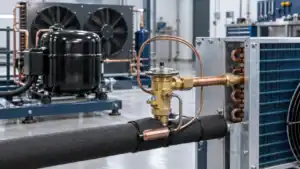
The phrase “shell and tube type heat exchanger” describes a family of constructions, not one standard part. A condenser, evaporator, oil cooler or process heat exchanger may use a shell and tube arrangement, but the tube-side and shell-side conditions can be very different.
This guide helps B2B buyers prepare a technical RFQ and compare proposed constructions. It is focused on industrial refrigeration and process cooling rather than a generic definition page.
How a shell-and-tube heat exchanger works
One medium flows through tubes while the other flows around the tubes inside the shell. The tube wall separates the streams while heat crosses the wall. The exchanger can be arranged for single-phase heating or cooling, condensation, evaporation or a combination of duties.
The actual flow path depends on pass partitions, baffles, nozzles and controls. The drawing should identify which medium is on the tube side, which is on the shell side, and where phase change occurs. Reversing those assumptions can change pressure drop, material compatibility, cleaning access and the required test plan.
Industrial refrigeration applications
Condensers
In a condenser, refrigerant rejects heat while changing from vapor to liquid. The cooling medium may be water, glycol or another process fluid. The design needs condensing condition, refrigerant, design pressure, cooling-fluid flow, entering temperature, fouling and approach temperature.
Evaporators and chillers
In an evaporator or chiller, refrigerant may boil on one side while a secondary fluid is cooled on the other. The RFQ should identify freeze risk, oil return, control range, flow distribution, pressure drop and cleaning method.
Oil and process cooling
Industrial systems may use shell-and-tube exchangers to cool oil, hydraulic fluid or a process stream. Fluid chemistry, viscosity, operating range and cleaning often drive the selection more than nominal refrigeration capacity.
| Application | Critical input | Common failure of an incomplete RFQ |
|---|---|---|
| Water-cooled condenser | Water quality, flow and design pressure | Fouling or insufficient heat rejection |
| Glycol chiller | Concentration, flow and freeze margin | Incorrect duty or excessive pressure drop |
| Ammonia or CO2 duty | Refrigerant, high-side pressure and materials | Incompatible pressure or safety assumptions |
| Oil or process cooler | Viscosity, chemistry and cleaning | Poor distribution or blocked passages |
Pass arrangement and temperature approach
Pass arrangement changes fluid velocity, pressure drop and temperature distribution. A single pass may have low pressure drop but different heat-transfer behavior from a multi-pass design. The right choice depends on flow, duty, allowable pressure drop and the desired approach temperature.
The RFQ should include inlet and outlet conditions for both media, not only the target outlet temperature. If the duty varies, provide the minimum, normal and peak points. A supplier can then identify whether the same exchanger can cover the range or whether controls, bypass or a larger surface are needed.
Flow direction and controls
Counterflow, crossflow or mixed arrangements affect temperature approach. Valves, bypasses, receivers, pumps and control sensors should be considered in the system review. A heat exchanger quotation should state what is included and what remains part of the customer’s system.
Materials, pressure and refrigerant compatibility
Material selection should consider tube-side and shell-side medium, pressure, temperature, corrosion, cleaning, joining and gasket requirements. Copper, stainless steel, carbon steel and other materials may suit different duties, but no generic material list replaces an application review.
For ammonia and CO2 systems, confirm design pressure, operating envelope, connection standard and applicable safety requirements. Do not infer compatibility from a similar-looking commercial coil. The shell, tube, headers, seals and test procedure all need review.
Coatings can be considered for a defined environment. State surface preparation, coated areas, masking, curing, inspection and acceptance. A coating may affect cleanability and thermal assumptions, so it should be part of the design record.
Fouling, cleanability and service access
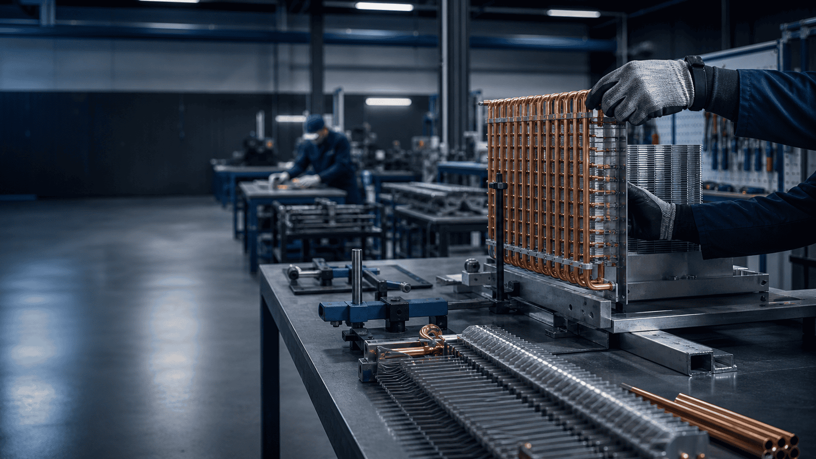
Heat exchangers lose performance when the tube or shell-side surfaces foul. Ask how the unit will be cleaned, what access is available, whether the bundle can be removed, and which side requires inspection. Water quality, process contamination, oil carryover and corrosion products should be included in the maintenance plan.
The most compact exchanger is not automatically the lowest lifecycle cost. A design with easier inspection or a removable bundle may be preferable when downtime and cleaning access matter. State the service interval and site access before finalizing the construction.
Mechanical envelope and RFQ data
Send the equipment drawing or define the envelope, supports, nozzles, orientation, lifting and removal path. The supplier needs:
- Tube-side and shell-side media.
- Duty, temperatures, flow rates and pressure drops.
- Operating and design pressure, vacuum and test requirements.
- Tube bundle, shell, gasket and coating preferences.
- Nozzle size, flange or connection standard and orientation.
- Supports, mounting, service clearance and removal direction.
- Fouling, cleaning, inspection and documentation requirements.
- Sample, quantity, lead time, packaging and delivery conditions.
Mark every unconfirmed line as an assumption. This prevents a low preliminary price from becoming a hidden design commitment.
Inspection and performance confirmation
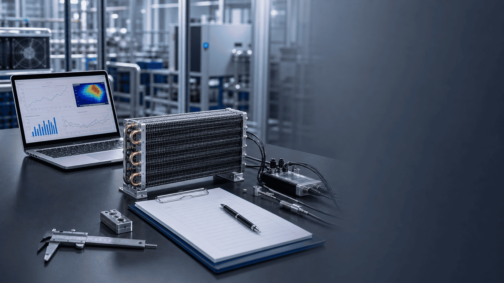
Define release evidence before the first sample. Dimensional inspection should cover critical interfaces and nozzle locations. Pressure or leak testing should state method and acceptance. A performance test should identify both fluids, inlet conditions, flow, duty and the permitted tolerance.
If the project only needs a replacement shell or bundle, do not automatically request a full laboratory performance report. If the operating condition has changed, a thermal review may be necessary even when the mechanical envelope is unchanged.
Shell-and-tube versus other heat-exchanger options
A shell-and-tube design may be preferred for pressure, serviceability, fluid separation or a particular duty, while a finned coil or plate exchanger may suit a different system. The comparison should use the same duty and constraints.
| Comparison point | Shell-and-tube | Finned coil or air cooler | Plate exchanger |
|---|---|---|---|
| Heat sink | Liquid or process fluid | Air or liquid depending on construction | Liquid or refrigerant depending on design |
| Service access | Depends on bundle and shell design | Usually air-side service access | Plate and gasket access varies |
| Key pressure issue | Tube, shell, tube sheet and seals | Tube, header and connections | Plates, seals and ports |
| Main selection data | Two-fluid duty, flow, pressure and fouling | Air condition, airflow, fluid or refrigerant | Fluid properties, pressure and approach |
This is a decision framework, not a claim that one type is always better. The selected exchanger must be checked against the actual application.
FAQ: shell-and-tube heat exchangers
What is a shell-and-tube heat exchanger used for?
It can heat, cool, condense or evaporate fluids in refrigeration, HVAC, process cooling, oil cooling and other systems. The tube-side and shell-side media define the actual duty.
What is the difference between shell-side and tube-side flow?
Tube-side flow passes inside the tubes; shell-side flow surrounds the tubes inside the shell. The choice affects pressure drop, materials, cleaning, phase change and service access.
How do I select a shell-and-tube exchanger?
Provide both media, duty, temperatures, flow, pressure, allowable pressure drop, fouling, materials, connections, envelope, cleaning method and test requirements.
Can shell-and-tube exchangers be used with ammonia or CO2?
They can be considered for industrial systems, but refrigerant pressure, materials, connections, safety and test requirements must be reviewed for the specific design.
What causes a shell-and-tube exchanger to lose performance?
Fouling, corrosion, blocked passages, poor flow distribution, incorrect operating conditions, leaks and control problems can all reduce performance. Site diagnosis is required before choosing a replacement.
Can Domi review a shell-and-tube RFQ?
Yes. Send the duty, fluids, pressure, drawings, materials, connections, quantity and inspection requirements for an engineering review.
Related Articles
- Tube bundle heat exchanger engineering guide
- Industrial heat exchanger replacement guide
- Industrial refrigeration evaporator selection guide
- Industrial refrigeration condenser-coil selection guide
- Industrial refrigeration solutions
- Engineering capabilities
Request a shell-and-tube review
Send the two-fluid duty, flow, temperatures, pressure, materials, envelope, connection drawing, cleaning method and test requirements. Domi can help separate the fixed design requirements from the options that need engineering confirmation.