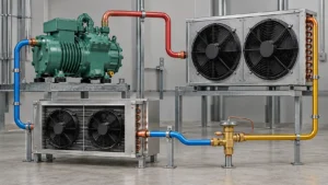
Custom HVAC coil sizing requires the thermal duty, air or fluid conditions, flow rate, refrigerant or secondary fluid, allowable pressure drop, mechanical envelope, connections, environment, and validation target; dimensions alone are not enough.

Searching for an HVAC coil sizing method often produces a calculator, a tonnage chart, or a formula for a simplified coil. Those tools can be useful for an early estimate, but an OEM or project engineer needs more information before a custom coil can be quoted or released. The coil has to exchange the required heat, fit the cabinet, work with the selected refrigerant or fluid, stay within pressure-drop limits, drain or defrost correctly, and be manufactured consistently.
This guide separates three decisions that are often mixed together: the thermal calculation, the coil construction and circuiting, and the mechanical interface. A supplier can help with all three, but the buyer should provide enough operating data to make the assumptions visible. If a project only has an old photograph or an outside dimension, the correct first step is a data-recovery exercise rather than a confident final size.
For a complete development route, review Domi’s HVAC and heat pump heat exchanger solutions and then send the information in the RFQ checklist near the end of this article. It is acceptable to begin with ranges, but mark every range that still needs confirmation.
What information is needed to size an HVAC coil?
The first sizing package should answer what the coil must do, what passes through it, how it will be installed, and how it will be verified. The following inputs are the minimum starting point for a meaningful supplier conversation.
| Input group | Examples of information | Why it changes coil sizing |
|---|---|---|
| Application | Evaporator, condenser, heat pump outdoor coil, indoor coil, chilled-water coil, reheat coil | Defines the heat-transfer role and possible operating modes |
| Thermal duty | Cooling or heating capacity, load range, rating point, part-load points | Determines the required heat transfer rather than just the physical size |
| Air side | Volume flow or mass flow, entering temperature, humidity, leaving target, allowable pressure drop | Drives face area, fin spacing, rows, drainage, and fan selection |
| Refrigerant or fluid side | Fluid identity, inlet/outlet temperatures, flow, pressure, phase, concentration | Determines circuiting, tube/port selection, materials, and safety review |
| Mechanical envelope | Face, depth, headers, connections, brackets, insertion direction, service clearance | Confirms that the finished assembly fits the equipment |
| Environment | Indoor, outdoor, coastal, industrial, chemicals, cleaning method, storage | Influences materials, coating, drain design, and packaging |
| Quality and validation | Leak/pressure, dimensional, performance, sound, defrost, documentation | Makes the quotation and release criteria measurable |
| Commercial program | Samples, pilot lot, SKU family, annual volume, release pattern, packaging | Affects tooling, setup, price, and production planning |
If the information is not available, write “to be confirmed” instead of filling in a generic value. A supplier can then tell you which missing input has the largest effect on the design.
Cooling, heating, condenser, and heat pump coil inputs
Different coil types need different emphasis. A cooling coil in a humid air stream must manage condensate, while a dry heating coil may be more constrained by leaving-air temperature and allowable pressure drop. A condenser coil has refrigerant desuperheating, condensing, and possible subcooling zones. A heat pump outdoor coil may reverse roles and must also be reviewed for frosting and defrost.
Evaporator and indoor cooling coil
For an evaporator or indoor cooling coil, collect entering dry-bulb and wet-bulb conditions, airflow, target leaving condition, refrigerant state, capacity, superheat or control assumptions, and allowable air-side pressure drop. The supplier also needs to know whether the coil is vertical, sloped, or installed above a drain pan. Fin spacing and surface treatment can affect water carryover, drainage, cleaning, and blockage risk.
Do not use nominal “tons” as the only input. The same nominal capacity can be achieved at different airflows, entering humidity, refrigerant temperatures, and pressure-drop limits. Those changes can alter face area, rows, circuiting, and the required drain arrangement.
Condenser coil
For a condenser, provide the refrigerant, entering gas or two-phase condition, condensing target, ambient or entering-air condition, airflow, desired subcooling if relevant, and maximum allowable pressure drop. State whether the coil must operate across a wide ambient range or only at a rated point. The coil may need distinct regions for desuperheating, condensation, and subcooling, and those regions influence circuiting and header design.
The AHRI 410 performance-rating scope is useful when identifying a forced-circulation air coil rating approach, but the RFQ must still define the specific refrigeration or HVAC duty and acceptance conditions.
Heat pump outdoor coil
For a heat pump outdoor coil, describe both heating and cooling modes if the coil operates in both. Include low-ambient conditions, expected frosting environment, defrost method, fan control, reversing-valve arrangement, sensors, drain path, and any cabinet clearance that affects airflow. A coil that is acceptable at a cooling rating point may not be acceptable when it becomes the evaporator in cold, humid weather.
The U.S. Department of Energy heat-pump systems overview provides system context for the reversing-cycle behavior. For a custom coil, the practical lesson is to provide mode-by-mode data rather than only the nameplate capacity.
Chilled-water or glycol coil
For a hydronic coil, state fluid identity and concentration, flow rate, inlet/outlet temperatures, design pressure, freeze protection, water quality, control valve arrangement, and cleaning or treatment requirements. Glycol concentration changes heat capacity and pressure drop. Water-side fouling and freeze risk may also change the required face area and circuit arrangement.
Do not transfer a refrigerant coil calculation directly to a water coil. The fluid properties, phase behavior, control method, and failure modes are different.
A practical HVAC coil sizing workflow
The most reliable workflow moves from system duty to geometry and then to production documentation.
Step 1: Define the rating points and operating range
Write the nominal point and the expected high/low range. A single rating point can hide a design problem at part load, high humidity, low outdoor temperature, or a reverse-cycle condition. If the program has multiple products, list each operating family separately rather than asking for one “universal” coil.
Step 2: Establish the thermal load and flow
Provide the target capacity or heat load, airflow or fluid flow, entering and leaving conditions, and any known control assumptions. If the load is still an estimate, provide a range and identify the source. The supplier may be able to size a preliminary coil around a range, but the quote should state what will change when the load is finalized.
Step 3: Set pressure-drop limits
Pressure drop is not a minor output to check after the coil is drawn. It affects the fan, pump, compressor, control stability, and overall energy use. State the allowable air-side and fluid/refrigerant-side pressure drop, or ask the supplier to propose an assumption. If the assumption is missing, two suppliers may quote different coil sizes while appearing to answer the same request.
Step 4: Define the face area and envelope
The available face area comes from the cabinet, but it should be checked against airflow and service space. Show the coil’s active face, total assembly, headers, connections, mounting points, drain pan, insulation, filter, fan, and removal path. A drawing with only width and height is rarely enough for a custom coil.
Step 5: Select construction and circuiting
After duty and envelope are clear, the supplier can recommend tube/fin or microchannel construction, tube or port arrangement, rows, fin spacing, circuits, headers, and materials. The design should balance thermal duty, pressure drop, manufacturability, corrosion, cleaning, and service.
Step 6: Review the sample and validation plan
Decide which results are required for a sample: fit, leak, pressure, thermal performance, airflow, drainage, sound, defrost, or visual/assembly checks. A sample can answer a mechanical question without proving production repeatability. State whether the sample must use production-intent tooling and materials.
Step 7: Release with controlled data
The approved drawing should identify revision, materials, surface treatment, dimensions, tolerances, connections, inspection points, and packaging. Use a controlled revision process when the supplier or buyer changes a feature. The ASME guidance on revision of engineering drawings and associated documents is a useful reminder that a drawing change is engineering information, not just a new file name.

How airflow, face area, fin spacing, and rows affect selection
Face velocity and face area
Face velocity is the airflow divided by the active face area. Raising face velocity can reduce the required face area, but it may increase air-side pressure drop, noise, water carryover, or frost sensitivity. Lowering face velocity may help wet-coil drainage and pressure drop, but it can increase the cabinet footprint and cost.
The face area should be calculated from the actual open face and installation arrangement, not only the outer frame. Filters, louvers, guards, return bends, and uneven approach flow can change the usable area.
Fin spacing
Tighter fins can create more surface in a given face area, but they may be more sensitive to dirt, frost, and cleaning damage. Wider spacing can improve access and reduce blockage risk, but may require more face area or rows to achieve the same duty. For a humid evaporator or heat pump outdoor coil, the wet and frosted conditions need to be considered rather than just the dry rating point.
Rows and circuit length
Adding rows can increase available surface, but it can also increase depth and pressure drop. Circuit length affects refrigerant distribution and pressure losses. The correct number of rows is the result of the target duty, flow, fluid properties, air-side limit, and package constraints.
Header and connection placement
Headers and connections can create an interface problem even when the core size is correct. Confirm connection orientation, access for brazing or service, clearance to the fan and cabinet, bracket positions, drain direction, and whether the coil is installed vertically, horizontally, or at an angle.
Thermal sizing is not the same as mechanical fit
A common project mistake is to accept a coil that fits the cabinet without proving that it meets the duty. The reverse also happens: a calculated core meets the load but cannot be assembled, serviced, drained, or connected. Treat the following checks as separate gates.
| Gate | Question | Evidence |
|---|---|---|
| Thermal | Does the selected coil meet the target duty at stated conditions? | Calculation, selection report, or test result |
| Air/fluid flow | Does pressure drop remain within the system limit? | Pressure-drop estimate or test |
| Mechanical | Does the finished assembly fit and mount? | Dimensioned drawing and sample fit check |
| Refrigerant/fluid | Are circuiting, materials, pressure, and connections appropriate? | Engineering review and specification |
| Drain/frost | Can condensate or defrost water leave the assembly safely? | Installation review and operating test |
| Production | Can the supplier repeat the design with the intended process? | Process review, inspection plan, pilot lot |
| Service | Can the buyer clean, repair, or replace the part? | Service note and replacement plan |
Passing one gate does not prove the others. Put the gates into the project schedule so the quote does not become a late-stage redesign.
What to put in a custom HVAC coil RFQ
The RFQ should help the supplier answer the same technical question without guessing. Use a table such as this one and attach a drawing or sample photographs.
| RFQ line | Buyer input to provide | Supplier response to request |
|---|---|---|
| Equipment | Model, application, operating modes, installation orientation | Confirm the proposed coil role |
| Thermal duty | Cooling/heating load, rating points, range, part load | State selection basis and assumptions |
| Air side | Flow, inlet temperature, humidity, outlet target, pressure-drop limit | Propose face, rows, fins, and air-side result |
| Fluid side | Refrigerant or fluid, temperatures, flow, design pressure | Propose circuiting, connections, and materials |
| Envelope | Core, assembly, brackets, headers, drain, access | Confirm fit and identify exceptions |
| Environment | Coastal, industrial, indoor high humidity, cleaning agents | Recommend material/coating and limitations |
| Validation | Fit, leak, performance, sound, defrost, documentation | List sample and test requirements |
| Program | Samples, pilot, monthly/annual volume, SKU mix | State tooling, MOQ, lead time, packaging |
Data hierarchy when some inputs are missing
If the project is early, prioritize data in this order:
- Application and operating mode.
- Refrigerant or secondary fluid.
- Capacity or heat-load range.
- Airflow or fluid flow and entering conditions.
- Pressure-drop limits.
- Mechanical envelope and connections.
- Environment and maintenance.
- Validation and commercial plan.
This order is not a substitute for a final specification. It simply shows what should be recovered first when the design is not yet complete.
Common HVAC coil sizing errors
Using nominal tonnage as the full specification
Nominal tonnage may describe a product class, but it does not provide airflow, humidity, entering temperature, refrigerant, circuiting, or pressure-drop limits. Use it as a label, not as the complete design input.
Copying an existing coil without recovering its duty
An existing coil can be a valuable dimensional reference. It may also contain a design compromise, an obsolete refrigerant, or a performance problem. Measure it, photograph its connections and brackets, identify the equipment mode, and recover the original rating information when possible.
Ignoring wet-coil and frost conditions
Dry rating calculations can miss condensate carryover, drain issues, and frost accumulation. State the humidity and low-temperature conditions if they matter to the application.
Setting no pressure-drop limit
When no limit is stated, the supplier may optimize for different objectives. The result may fit and transfer heat but require more fan or pump power than the system allows.
Changing the envelope after thermal selection
A smaller cabinet, moved connection, reduced service clearance, or changed fan can invalidate the selection. Freeze the mechanical interface before ordering production tooling.
Treating a calculator as a release document
A calculator can support an early estimate. It does not replace a controlled selection report, drawing review, sample, and system validation. The input assumptions must travel with the result.
How supplier engineering support should work
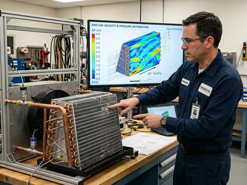
Good engineering support is visible in the questions the supplier asks. A supplier should clarify the duty, identify missing inputs, show assumptions, and explain what the sample will prove. The buyer should be able to distinguish a preliminary recommendation from an approved design.
Before a quote
Send the drawing, equipment context, operating data, and quantity plan. Ask the supplier to flag unknowns rather than silently selecting a default. If several constructions are possible, request a short comparison with the same duty and package assumptions.
During drawing review
Check datums, connections, mounting, drain direction, tolerances, material and coating notes, inspection points, and revision. Confirm that the drawing represents the production-intent assembly, not only a simplified thermal core.
During sample review
Record whether the sample passed fit, leak, dimensions, thermal performance, air-side pressure drop, drainage, and any control or defrost checks. Separate “not tested” from “passed.” A missing test is not a passing result.
Before production release
Confirm that the supplier’s process, tooling, material supply, inspection, packaging, and documentation match the approved design. If the program includes several SKUs, define which features are common and which require a new revision or setup.
Domi’s engineering capabilities, rapid prototyping route, and testing lab can be used as the next discussion points, subject to confirming the exact deliverables for the project.
A worked planning example without a misleading universal formula
Suppose an OEM knows that a new air handler needs a cooling coil but has not finalized the cabinet. The buyer should not ask for “a 3-ton coil” alone. A better planning record might say:
- The coil will cool a stated airflow range at a specified entering dry-bulb and wet-bulb range.
- The buyer has a maximum face width and depth, a preferred connection side, and a defined drain direction.
- Air-side pressure drop must remain below a system limit at the design airflow.
- The coil will be installed indoors but may see humid air and regular cleaning.
- Samples must confirm fit, leakage, dimensions, and system performance before the first production release.
The supplier can then propose a preliminary face area, fin spacing, number of rows, circuiting, materials, and a test plan. If the cabinet later changes, the impact is visible. The project has not pretended that a nominal tonnage formula is a finished design, but it has created enough structure to move forward.
A preliminary sizing worksheet for an incomplete project
An early-stage OEM project can still create a useful worksheet before every value is final. The purpose is to show the supplier what is known, what is estimated, and what must be confirmed before the design is released.
| Worksheet line | Example entry format | Status to mark |
|---|---|---|
| Equipment role | Indoor cooling coil for a packaged air handler | Confirmed or preliminary |
| Target duty | Cooling load range with the source of the estimate | Range, not a false exact value |
| Airflow | Minimum, nominal, and maximum flow | Confirmed, calculated, or open |
| Entering air | Dry-bulb, wet-bulb, humidity, altitude if relevant | Test point or design range |
| Leaving air | Target temperature/humidity or allowable range | Confirmed or to be selected |
| Pressure drop | Air-side limit and any system fan constraint | System limit or supplier proposal |
| Envelope | Maximum face, depth, connection side, drain side | Fixed versus negotiable dimensions |
| Construction | Existing tube/fin, microchannel, or open option | Requested or supplier recommendation |
| Environment | Indoor, coastal, industrial, wash-down, cleaning | Exposure matrix or open question |
| Validation | Fit, leak, performance, drainage, sound, or other | Required, optional, or not applicable |
The worksheet should travel with the quote and drawing. When a value changes, the buyer can see whether it affects thermal duty, pressure drop, geometry, materials, or validation. This is more reliable than changing one number in a calculator and forgetting which version produced the previous selection.
Turn the worksheet into a supplier response
Ask the supplier to return the worksheet with three columns: buyer input, supplier assumption, and confirmation needed. This format keeps a preliminary selection honest. It also gives procurement a concise document to attach to a quotation instead of relying on a long email thread. If the supplier proposes a different face area, row count, fin spacing, or circuit arrangement, the change should be visible next to the input it affects.
For an active program, keep one worksheet per equipment revision. Do not overwrite a previous selection when the fan, refrigerant, cabinet, or target capacity changes. A dated selection record lets the engineering team explain why two similar-looking coils have different dimensions or connections. It also helps quality decide which sample and inspection records belong to which part number.
The worksheet is also useful when the supplier’s first proposal does not fit. The buyer can point to the fixed dimensions, negotiate the variables that are still open, and ask for a second selection without restarting the entire project. Keep the old result in the file and mark it superseded. That small habit prevents an outdated coil calculation from being attached to a later purchase order.
If the buyer needs a calculator, keep it as an internal planning aid and show the inputs beside the result. The supplier’s formal selection should still use the approved operating conditions and drawing. This distinction protects the project when the early calculator used a nominal airflow or a default fluid property that is later replaced by measured equipment data.
Use ranges responsibly
Ranges are useful when the system is still being designed. For example, a supplier may compare a low, nominal, and high airflow while the fan is being selected. However, a range must have boundaries. “High humidity” does not tell the supplier whether the coil will see a wet rating point, a saturated start, or a short peak condition. “Low ambient” does not define the frosting or defrost test.
Write the source and confidence next to the range. A measured airflow, a simulation estimate, a nameplate value, and a buyer target are different types of evidence. The supplier can then identify which variable deserves an early sample or system test.
Sizing several coil SKUs without losing control
OEM programs often need a family of coils rather than one part. The family may share a cabinet, fan, refrigerant, or material, but its face dimensions and loads can vary. Build a matrix before requesting a final quote.
| SKU field | Why it matters to selection |
|---|---|
| Model and revision | Prevents a preliminary drawing from being used on a changed cabinet |
| Capacity range | Shows whether one coil platform can cover the products |
| Airflow | Determines face velocity, pressure drop, and fan compatibility |
| Face and depth limits | Shows whether row or fin changes are possible |
| Connections | Affects circuiting, service access, and tooling |
| Environment | May split the family into different materials or surface treatments |
| Demand and release | Influences tooling, material buying, and production planning |
Ask the supplier to distinguish a shared platform from a universal coil. Shared tooling can be valuable, but forcing one geometry to cover very different duties can increase pressure drop, reduce operating range, or create an unnecessary material compromise. A good family plan makes the common features visible without hiding the differences.
When to recalculate
Recalculate or request a design review when the refrigerant, airflow, entering conditions, capacity, fin spacing, row count, tube or port geometry, connection layout, coating, cabinet, or control mode changes. A drawing revision may look small but still affect the thermal or mechanical basis. Keep the selection report with the drawing revision so the production team knows which result was approved.
The ASHRAE standards and guidelines library and AHRI resources are useful places to confirm which rating, testing, or documentation references belong in the project brief. The supplier still needs the actual equipment duty and acceptance conditions.
Frequently asked questions
Can I size a custom HVAC coil from the old part’s dimensions?
Dimensions are a useful starting point, not a complete sizing method. Add the application, fluid, capacity, airflow, entering conditions, pressure-drop limit, connections, environment, and validation requirements. The old part may have been designed for a different system condition.
Do I need to know the exact heat load before contacting a supplier?
An early range is acceptable if it is clearly labeled as a range and the missing information is listed. The supplier can help identify which values must be confirmed before final selection. Do not present a rough estimate as a guaranteed duty.
Is there a universal HVAC coil sizing calculator?
There are calculators for particular coil types and assumptions, but no generic calculator can replace application-specific fluid properties, conditions, pressure-drop limits, geometry, and validation. Use a calculator for an estimate and a controlled selection process for release.
How do I size a heat pump outdoor coil?
Provide data for the operating modes, including heating and cooling if the coil reverses, low-ambient conditions, frosting environment, defrost method, airflow, refrigerant, pressure-drop limits, cabinet envelope, and drainage. The outdoor coil should be evaluated as part of the complete system.
What is the most important airflow input?
The supplier normally needs the flow rate and the entering air condition, including temperature and humidity when the coil is wet. Also provide the allowable pressure drop and any nonuniform approach flow caused by fans, filters, louvers, or bends.
How many rows should an HVAC coil have?
There is no universal row count. Rows interact with face area, fin spacing, circuiting, fluid conditions, pressure drop, package depth, and the target duty. Ask the supplier to explain the selected row count at the stated rating point.
What drawings should I send for a quote?
Send the coil assembly drawing, interface or cabinet drawing, connection details, mounting and drain information, and any old sample photographs. Mark the revision and identify dimensions that are fixed versus negotiable.
Can Domi help with an incomplete RFQ?
Yes, send the information that is available and label the missing values. Domi can then identify the next engineering questions, propose a development path, and confirm what is needed for a quotation or sample. Use the contact page to submit the drawing and data.
Related articles
- Microchannel vs Fin-Tube Coils for HVAC Systems
- R32 vs R410A HVAC Coil Design
- Hydrophilic Aluminum Fins for HVAC Evaporator Coils
- Heat Pump Outdoor Coil Frosting and Defrost Design
- HVAC Coil Corrosion Protection Options
- What Is a Heat Exchanger? Types, Uses and How It Works
Final takeaway
Good HVAC coil sizing begins with operating conditions and ends with a controlled, manufacturable assembly. Capacity, airflow, pressure drop, face area, rows, fin spacing, circuiting, materials, connections, drainage, service, and validation all belong in the same conversation. If a required input is missing, record it as an open item instead of hiding it inside a generic calculator result.
Send Domi the available drawing, duty, fluid, airflow, environment, and quantity plan. The earlier the thermal and mechanical questions are reviewed together, the less likely the project is to discover that a “correctly sized” coil cannot be mounted, serviced, or produced consistently.