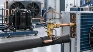
Heat pump outdoor coil frosting is driven by outdoor temperature and humidity, coil surface conditions, airflow, refrigerant operation, and run time; a reliable defrost design coordinates sensing, start and termination logic, valves, fan control, drainage, and system validation rather than relying on a fixed timer alone.
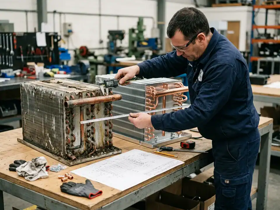
When a heat pump outdoor coil begins to frost, the visible ice is only the symptom. The root cause can involve outdoor temperature and humidity, coil surface temperature, airflow, refrigerant charge or distribution, fan operation, control logic, installation clearance, water drainage, or the length of the heating run. That is why heat pump coil defrost design should be treated as a system engineering topic rather than a timer setting.
During heating operation, the outdoor coil can act as the evaporator. Under suitable outdoor conditions, moisture in the air condenses and freezes on the surface. A layer of frost changes airflow and heat transfer. The system may then enter a defrost mode, temporarily changing the refrigerant flow or controls so that heat reaches the outdoor coil and melts the ice. The equipment must manage the water after melting and return to heating without creating a new fault.
This guide is for heat pump OEMs, controls engineers, equipment integrators, procurement managers, and suppliers reviewing a new outdoor coil. It explains the design questions that should appear in a project checklist. For the broader product context, see Domi’s HVAC and heat pump heat exchanger solutions, then send the low-ambient operating range, coil drawing, airflow, refrigerant, and controls information for an engineering review.
Why does a heat pump outdoor coil frost?
Frost forms when the outdoor coil surface is cold enough for moisture in the surrounding air to deposit and freeze. The exact point depends on air temperature, dew point, surface temperature, airflow, refrigerant conditions, coil geometry, and the time spent in the operating condition. Frost can be light and normal for a period, or it can become a sign of poor airflow, low charge, sensor error, drainage trouble, or an unsuitable control sequence.
Outdoor temperature and humidity
Cold, humid air can create a high frosting risk. A slightly warmer but saturated condition can also deposit moisture rapidly. The project should define the climate or test points that matter rather than assuming that “winter” is one condition. If the unit will be used in several regions, include a range of temperature and humidity conditions.
Coil surface temperature and refrigerant operation
The coil surface can be colder than the outdoor air when the system is extracting heat. Refrigerant distribution, expansion-device control, compressor operation, and circuiting affect the surface temperature. A blocked circuit or uneven airflow can create local frost patterns that are not explained by the average rating point.
Airflow and installation
Dirty filters, a blocked fan, incorrect rotation, tight clearances, snow, leaves, or a poor installation can reduce airflow. The coil may then run at a different temperature and accumulate ice. The U.S. Department of Energy heat-pump systems guide provides a useful system-level explanation of heat-pump operation; the engineering lesson is to check the equipment and installation, not just the coil face.
Time and operating history
Frost may not appear immediately. It can build during a long heating run, after a change in load, or when the outdoor humidity changes. A control that looks correct in a short test may behave differently across a longer duty cycle. Record the run time, coil temperature, outdoor condition, airflow, and defrost history when investigating the problem.
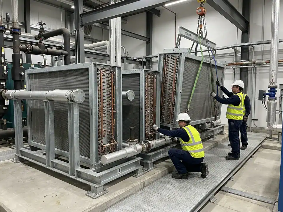
Frosting symptoms versus root causes
Use a diagnostic table rather than treating every ice pattern as the same problem.
| Observation | Possible causes to investigate | What to verify |
|---|---|---|
| Light, even frost | Normal low-temperature operation before a controlled defrost | Sensor, control sequence, run time, return to heating |
| Frost concentrated on one area | Air distribution, refrigerant distribution, blockage, sensor location | Coil circuiting, fan, filters, temperature map |
| Rapid full-coil ice | Low airflow, low outdoor condition, control fault, charge or system issue | Airflow, pressures, temperatures, controls, installation |
| Ice at the bottom or pan | Defrost water, slope, blocked drain, refreezing | Drain path, pan heat or protection, clearances |
| Frost returns immediately after defrost | Incomplete melt, sensor termination, airflow, water refreeze | Coil surface, termination logic, drainage, fan sequence |
| No defrost when ice accumulates | Sensor, board, wiring, threshold, or control logic | Signal chain and controlled test condition |
This table is not a field diagnosis. It shows why a supplier and OEM should collect data before changing the coil or controls. A visible symptom can have several causes.
Defrost control methods and their trade-offs
Time-based control
A time-based method starts defrost after a defined run time or schedule. It can be simple, but it may initiate defrost when little frost exists or delay defrost when frosting is heavy. The right interval depends on the product, climate, coil, airflow, and control strategy. Avoid publishing a universal cycle interval.
Temperature-based control
A sensor can monitor coil, outdoor, or refrigerant-related temperature. Temperature data may provide better information than time alone, but the sensor position and calibration matter. A sensor that is insulated from the actual frost zone or placed near a warm header may not represent the critical surface.
Combined or adaptive control
Many systems combine run time, temperature, pressure, airflow, or other state information. The advantage is that the controller can consider more than one symptom; the trade-off is increased validation and fault-handling complexity. The OEM should define what happens when a sensor fails, a signal is out of range, or the coil does not reach the expected temperature after a defrost command.
The NACHI heat-pump defrost-cycle explanation is useful for basic service context. For an OEM design, use a controlled sequence specification that identifies start conditions, termination conditions, maximum duration, recovery, alarms, and test cases.
What a defrost sequence must coordinate
A design review should identify the actions for:
- Reversing valve or refrigerant flow change.
- Compressor operation and protection.
- Outdoor fan start, stop, or speed control.
- Indoor fan and auxiliary heat response.
- Sensor sampling and filtering.
- Defrost start and termination.
- Maximum run time and fault timeout.
- Water drainage and refreeze prevention.
- Return to heating and capacity recovery.
- User-visible sound, temperature, or comfort effects.
The Purdue International Refrigeration and Air Conditioning Conference paper and the ACEEE heat-pump defrost research paper are useful examples of why defrost is a system-performance and control topic, not just a visual ice problem. Use the applicable current research and standards for the actual design.
Outdoor coil design factors that affect defrost
Fin spacing and frost accommodation
Frost reduces open air passages. A tight fin spacing may deliver useful dry-surface area but can become blocked sooner under a heavy frost load. Wider spacing may provide more room for frost and cleaning but changes the core size, pressure drop, and thermal selection. Choose the spacing with the climate, airflow, maintenance, and package constraints in mind.
Circuiting and refrigerant distribution
The coil needs an appropriate refrigerant path in the heating and cooling modes. Poor distribution can create uneven surface temperatures and localized frost. Headers, circuits, connections, and the expansion device should be reviewed together.
Air distribution and fan arrangement
The fan, grille, louver, filter, cabinet, and coil shape affect the velocity map. A coil that tests well in uniform airflow may frost differently in a production cabinet with a bend, a wraparound arrangement, or a side discharge. Include the actual air path in the validation plan.
Drainage and the bottom of the coil
Defrost turns frost into water. That water needs a clear route out of the coil and cabinet. The pan, slope, drain hole, end plates, support brackets, insulation, and installation clearance can create low points where water refreezes. The ASHRAE refrigerant designations page is an example of the broader safety and system context that must be kept current; the specific defrost drainage solution still belongs to the equipment design.
Coatings and surface treatments
Surface treatments can be selected for corrosion, wetting, cleaning, or other goals. They should not be presented as a universal anti-frost solution. Review how a coating behaves during repeated freeze/thaw, defrost water, cleaning, and handling. If the project uses a hydrophilic fin system, see the related guide on hydrophilic aluminum fins.
OEM defrost design review checklist
Use a checklist that brings coil, controls, and installation together.
| Review item | Questions to answer | Evidence |
|---|---|---|
| Climate | What temperature, humidity, snow, rain, and wind conditions matter? | Test matrix or design range |
| Coil | What are face, rows, fin spacing, circuiting, material, and connections? | Controlled assembly drawing |
| Airflow | What fan, grille, clearance, and pressure-drop limits apply? | Airflow calculation or test |
| Sensors | Where are coil and outdoor sensors located and protected? | Sensor drawing and calibration rule |
| Start | What conditions request defrost? | Control sequence and test case |
| Termination | What confirms that the coil is clear enough? | Threshold, timer limit, or state logic |
| Fan/valve | How do fan and reversing valve respond? | Sequence table and failure response |
| Drainage | Where does meltwater go and what can refreeze? | Pan, slope, drain, and installation review |
| Recovery | How does the unit return to heating? | Capacity, temperature, and control check |
| Faults | What happens if a sensor or valve fails? | Diagnostic and safe-state behavior |
Make the checklist a release document. If the project has not tested a line, mark it as open rather than “passed.”
How to submit an outdoor coil design request
Give the supplier enough context to separate coil design from system control:
- Equipment type and model family.
- Heating and cooling modes.
- Refrigerant and operating pressure/temperature range.
- Outdoor temperature and humidity range.
- Capacity targets and airflow.
- Cabinet, fan, grille, clearance, and drain drawings.
- Defrost method or preferred control interface.
- Frost history, photos, and failure conditions if it is a replacement.
- Material, coating, corrosion, and cleaning requirements.
- Samples, annual volume, SKU mix, packaging, and validation plan.
If a design is still early, say which values are estimates. A supplier can propose a preliminary concept, but the final coil should be selected against controlled conditions.
Common mistakes in heat pump defrost design
Using a fixed timer as the complete strategy
Time can be part of a sequence, but it cannot describe every climate or load condition. The product should define sensing, start, termination, maximum duration, and fault response.
Measuring the wrong place
A sensor near a header, protected from the airflow, or separated from the frost zone may report a misleading temperature. Review the sensor position against the actual coil and frost pattern.
Ignoring meltwater after the defrost command
The ice may be gone from the visible face while water remains in the pan or low points. If that water freezes again, the next cycle starts with a worse condition. Validate drainage and refreezing across the relevant ambient range.
Testing only the coil outside the cabinet
Production airflow, fan control, louvers, filters, and clearances can change the frost pattern. Include the actual enclosure or a representative fixture.
Claiming that a coil coating eliminates frost
Coatings can be selected for particular surface or corrosion objectives, but frost is a system condition involving temperature, humidity, airflow, refrigerant, and controls. Use evidence and conditional language.
Forgetting user experience
Defrost can affect supply-air temperature, fan noise, steam or water, and perceived comfort. Document the expected sequence and recovery so service and customer-support teams can explain it.
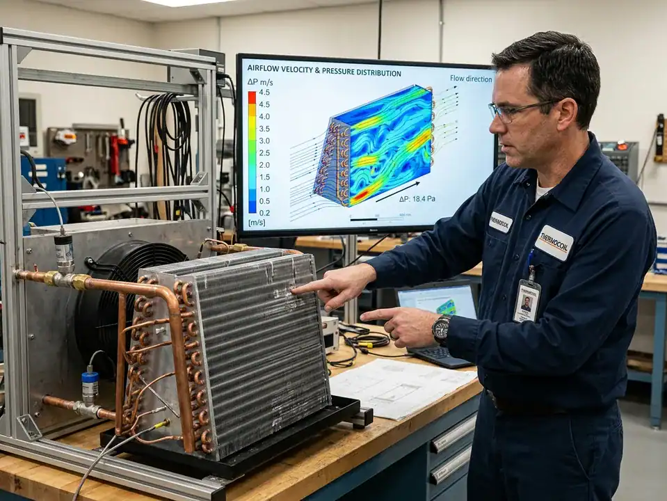
How to validate the coil and controls together
Define a test matrix
Include the operating points that represent the product’s real market. Vary outdoor temperature and humidity, airflow, load, run time, and initial coil condition where relevant. State the starting condition, the frost level, the defrost request, and the termination criteria.
Record the variables that explain the result
At minimum, record outdoor air, coil temperatures at useful locations, airflow, refrigerant pressures or system variables allowed by the project, fan state, valve state, sensor signals, defrost duration, water behavior, and return-to-heating performance. A single “defrost passed” label is not enough to diagnose a later failure.
Separate design verification from production inspection
The first system test can verify the design. Production inspection checks that each coil and control assembly matches the approved design. They are different activities. The production plan may include dimensions, materials, leak checks, sensor installation, connection orientation, and traceability.
Domi’s engineering capabilities, testing lab, and custom coil fabrication pages are the logical starting points for a discussion about the coil portion of the project. Confirm the exact tests and deliverables before writing them into a purchase order.
A defrost sequence example for an engineering review
The following sequence is a framework for discussion, not a universal control program. The actual thresholds and timing must come from the equipment design and test data.
Normal heating operation
The controller monitors outdoor conditions, coil or refrigerant-related temperatures, airflow, fan state, and the operating history. The coil operates as the outdoor evaporator. The design team should know which signals are available and which are only estimates. A missing or noisy signal should have a defined response.
Defrost request
The controller identifies that the combination of run time, sensor condition, temperature trend, or other state indicates a need for defrost. The start rule should include a maximum run-time or safety boundary so that the unit does not remain in an inappropriate state. The control record should show why the request was made.
Defrost execution
The system changes the valve, compressor, fan, auxiliary heat, or other controls according to the approved sequence. Record the transition time, the coil temperature response, the fan state, water movement, and any user-visible effect. The sequence should protect the compressor and components if the expected temperature or pressure response does not occur.
Termination and recovery
Defrost ends when the coil reaches the defined condition, the maximum duration is reached, or a fault rule intervenes. The controller then returns to heating, restores the fan and valve states, and checks that the coil and system are recovering. The project should define what counts as a successful return and what happens after an incomplete or interrupted defrost.
This sequence makes the connection between coil geometry and controls visible. A different fin spacing, circuiting, sensor location, cabinet, or drain can change how the same control sequence behaves.
Frost pattern interpretation during development
Frost is a spatial problem as well as a time problem. Photograph or map the coil at consistent intervals during a controlled test. Note whether frost begins at the inlet, outlet, top, bottom, edge, or a region behind an airflow obstruction. Compare the pattern with sensor locations and circuiting.
| Pattern | Questions to ask before changing the design |
|---|---|
| Even frost across the face | Is the control sequence working and the drainage adequate? |
| Frost at one edge or corner | Is the airflow or refrigerant distribution uneven? |
| Frost near the inlet only | Is the circuiting, expansion device, or temperature sensor influencing the local condition? |
| Ice at the lower pan | Is defrost water leaving the coil or refreezing? |
| Heavy frost behind a grille or louver | Is the approach airflow blocked or recirculating? |
| Different pattern after cabinet assembly | Did fan, clearance, grille, filter, or installation change the velocity map? |
Pattern evidence should be combined with operating data. A photo can show where the ice is, but not why it formed. The supplier and OEM should be cautious about changing the coil based on one unrepeatable observation.
Production and service requirements for a defrost-ready coil
The coil should be manufactured and documented so the defrost design remains repeatable. Check fin spacing, row count, circuiting, headers, connection orientation, sensor mounting, brackets, pan interface, and coating or material notes. A small change at the bottom of the coil can affect water flow even if the active face looks unchanged.
Service documentation should show sensor locations, connection identification, approved cleaning, drainage inspection, fin protection, and the symptoms that require a controls check. If the coil is a service replacement, the package should make clear whether the part is compatible with one model/revision or a wider family.
The ASME drawing revision guidance is a useful reminder to control changes in the drawing and related documents. A coil supplier should not silently substitute a fin, header, sensor bracket, or connection that changes the approved defrost basis.
Packaging and installation matter
Bent fins, blocked drain holes, damaged headers, and missing spacers can change frost and defrost behavior before the unit starts. Specify protective packaging and a receiving inspection. On site, confirm the clearance, level, drain, fan, grille, snow or debris exposure, and sensor connection. A development test cannot compensate for an installation that blocks the airflow or traps meltwater.
Low-ambient design questions before the first sample
Ask the team to answer these questions before the coil drawing is frozen:
- What outdoor temperature and humidity range is the product expected to cover?
- Is the outdoor unit exposed to wind, snow, rain, salt, leaves, or a wall that can recirculate air?
- What is the minimum and maximum airflow, and how does the fan control change it?
- Does the coil operate as both an evaporator and condenser during the product modes?
- Which circuiting, headers, connections, and sensors are fixed by the current cabinet?
- Where does defrost water go at the lowest temperature after it leaves the coil?
- What happens if the sensor, reversing valve, fan, or drain is abnormal?
- What is the sample intended to prove, and what must be tested in the complete unit?
The answers help the supplier identify whether the primary risk is thermal capacity, frost distribution, control sequence, drainage, corrosion, or mechanical assembly. They also make the sample plan more efficient. A fit sample and a cold-weather defrost test are different deliverables; neither should be hidden inside a single “prototype” line.
Keep design assumptions next to the control sequence
The coil drawing, sensor drawing, control sequence, and test plan should reference the same equipment revision. If a sensor moves, a circuit changes, the fan is resized, or the cabinet clearance changes, the team can immediately see which defrost assumptions need review. This is particularly important when several heat pump models share a family of outdoor coils.
Define service communication
The owner should know that a temporary frost layer can be normal under certain conditions, while a solid ice block, repeated short cycling, blocked drain, or failed defrost may require service. Give the service team a way to distinguish a normal sequence from a fault without telling them to replace the coil blindly. The service document should identify the coil revision, sensor location, drain inspection, and escalation path.
The same language should appear in the quotation and commissioning checklist. State which frost and defrost behavior is expected, which conditions are outside the validated range, and which observations require a controls, airflow, refrigerant, or drainage investigation. This avoids turning every customer complaint into an unplanned coil change.
Keep the coil revision and control revision together in the service record. A replacement made for one revision may not carry the same sensor bracket, circuiting, or drain detail as a later model, even when the outside dimensions are close.
That small documentation step protects both the buyer and the supplier: the field team gets the right part, and the engineering team can investigate a frost complaint against the correct operating and control basis.
The record should remain with the product revision instead of living only in a service email or a technician’s memory.
That is a simple quality-control step, but it prevents many avoidable part and diagnosis errors.
It also makes a later design change easier to assess because the affected assumptions are written down.
The result is a clearer handoff from development to production and service.
It also gives the buyer a concrete list of evidence to request before accepting a “defrost-ready” coil description.
That is safer than relying on a label without a test basis.
Use the same standard for every supplier quotation.
When a frost complaint reaches the supplier, the first request should be the operating record, not a new coating or a different fin. Ask for outdoor temperature and humidity, run time, airflow, sensor values, valve and fan states, defrost duration, water path, and photographs. If those data are unavailable, label the diagnosis as preliminary. A replacement coil may be appropriate, but the project should know whether it is correcting a coil design issue or masking an airflow, control, charge, or installation problem.
For a new product, collect the same evidence during development. A test log should identify the initial coil condition, outdoor point, airflow, start time, frost pattern, defrost request, termination reason, water movement, recovery, and any fault. This makes it possible to compare two circuiting or fin-spacing options without relying on a technician’s impression. It also gives the service team a reference for what normal operation looks like under the validated conditions.
Use the log to distinguish a design change from a service correction. If two samples have different frost patterns under the same cabinet and controls, the coil or airflow may need review. If the pattern changes after a fan, sensor, valve, or installation change, the investigation should follow that system change instead of assigning the result to the coil alone.
Keep the complete log with the equipment revision and test fixture identification. This record helps distinguish a design change from a service correction.
Frequently asked questions
What does a heat pump defrost cycle do?
It temporarily changes the system’s operation so heat reaches the outdoor coil and melts accumulated frost. The exact valve, compressor, fan, auxiliary heat, sensor, and termination sequence depends on the equipment design.
How often should a heat pump defrost?
There is no universal interval. The need depends on outdoor conditions, coil, airflow, controls, load, and the equipment’s design. A fixed number of minutes should not be treated as a general engineering rule.
Why does a heat pump outdoor coil freeze solid?
Possible causes include heavy frost conditions, poor airflow, a control or sensor fault, refrigerant or circuiting problems, blocked drainage, installation clearance, or incomplete defrost. A qualified technician should diagnose the complete system.
Can a larger fin spacing eliminate defrost?
No. Fin spacing can affect frost accommodation and pressure drop, but it cannot eliminate the need for defrost in conditions where the coil accumulates ice. The coil and control strategy must be designed together.
Does a hydrophilic coating stop heat pump frost?
Do not assume it does. A surface treatment may be selected for condensate or corrosion objectives, but frost depends on the operating conditions and system. Test any claimed benefit on the actual coil and equipment.
What causes ice to return after defrost?
Possible causes include incomplete melting, poor drainage, refreezing water, a sensor that terminates too early, airflow problems, or an operating condition that creates frost immediately. Record the sequence and water path before changing the design.
What information does a coil supplier need for defrost design?
Provide the refrigerant, heating and cooling duty, outdoor conditions, airflow, coil geometry, fin spacing, circuiting, sensors, valve/fan sequence, drain path, cabinet clearances, failure history, and validation requirements.
Can Domi help with a heat pump outdoor coil replacement?
Send the model information, existing coil drawing or sample, operating conditions, frost history, dimensions, refrigerant, connections, and requested quantity. Domi can then confirm the information needed for a custom review and quotation.
Related articles
- Microchannel vs Fin-Tube Coils for HVAC Systems
- How to Size a Custom HVAC Coil
- R32 vs R410A HVAC Coil Design
- Hydrophilic Aluminum Fins for HVAC Evaporator Coils
- HVAC Coil Corrosion Protection Options
- What Is a Heat Exchanger? Types, Uses and How It Works
Final takeaway
Reliable heat pump coil defrost design coordinates the coil, refrigerant circuit, airflow, sensors, valves, fans, controls, drainage, installation, and validation. Frost can be normal for a period, but the design must control how much accumulates, when defrost starts, when it ends, where the water goes, and how the unit returns to heating.
If you are developing or replacing an outdoor heat pump coil, send Domi the operating range, frost history, coil drawing, airflow, refrigerant, controls, and drain details. A complete system brief gives the supplier a chance to solve the cause rather than only change the visible metal surface.