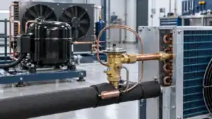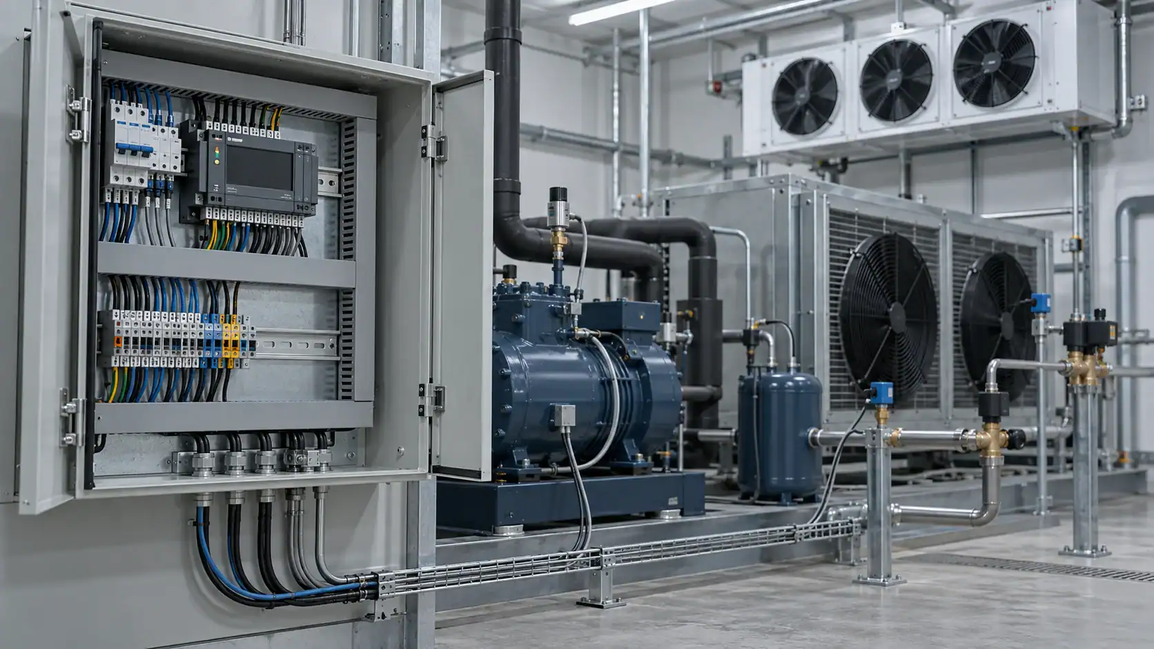
Refrigeration controls are the sensors, switches, valves, relays, controllers, safety devices, and supervisory logic that measure system conditions and then start, stop, modulate, protect, defrost, or alarm refrigeration equipment. A useful OEM or commercial RFQ names the controlled variable, load, refrigerant circuit, defrost sequence, electrical interface, alarm behavior, and communication requirement. This guide gives engineers, procurement teams, contractors, and distributors a practical way to define that scope before comparing hardware or asking for a replacement.
What refrigeration controls do in a system
The word “controls” describes a function across the refrigeration circuit, not one universal box. A control may sense room temperature, evaporator temperature, suction pressure, discharge pressure, liquid level, flow, door position, motor current, or another condition. It then changes an output: a compressor contactor, condenser fan, evaporator fan, solenoid valve, expansion valve, defrost heater, pump, alarm, or data signal.
The ASHRAE chapter on refrigerant control devices groups practical control work around pressure, temperature, liquid level, and refrigerant flow. The Copeland commercial refrigeration controls reference shows how the product boundary can include pressure and temperature controls, expansion valves, solenoid valves, oil controls, system protectors, contactors, and electronic refrigeration controls.
For a buyer, the most useful question is: What condition must stay within limits, and which equipment must respond when it changes? That question prevents a thermostat, controller, panel, and supervisory system from being treated as interchangeable products.
Define the control boundary before choosing hardware
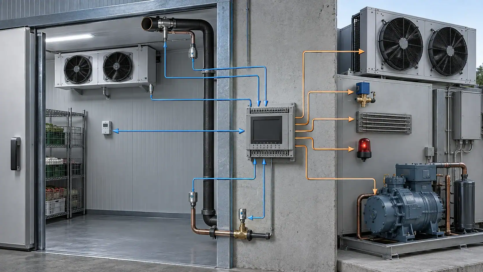
Start by drawing the boundary around the equipment being controlled. A self-contained cabinet may contain its controller, sensors, compressor, fans, valves, defrost hardware, and alarm output. A remote cold-room system may divide those functions between an evaporator controller, a condensing unit, a panel, a rack controller, and a facility monitoring layer. An industrial process skid may add pumps, level instruments, interlocks, and a plant PLC.
The ASHRAE refrigerated-facility design guidance describes control architecture across compressor packages, condensers, evaporators, and refrigerant-flow management. It also cautions that the architecture should be designed before control component vendors are selected. Use that principle in the RFQ: agree what is inside the supplier’s scope before asking for part numbers.
| Control boundary | Typical contents | Buyer must define | Common scope error |
|---|---|---|---|
| Component control | Sensor, pressure switch, thermostat, solenoid, contactor, or valve driver | Controlled variable, range, setpoint, differential, signal, and load | Ordering a device by appearance without confirming its input or output |
| Unit control | Controller, sensors, compressor and fan outputs, defrost, alarms, display | Equipment sequence, relay or analog outputs, sensor count, and failure behavior | Assuming a controller includes the panel, wiring, protection, or field sensors |
| Panel control | Enclosure, disconnect, protection, terminals, controller, relays, drives, and wiring | Incoming power, motor loads, I/O list, enclosure environment, and service access | Comparing a wired panel with a bare controller as if they were the same scope |
| Rack or plant control | Multiple compressors, suction groups, condensers, evaporators, valves, and common alarms | Staging, capacity control, pressure targets, oil management, defrost coordination, and network | Specifying a single local thermostat for a coordinated multi-circuit plant |
| Supervisory layer | Data logging, remote alarms, dashboards, permissions, and gateway functions | Points list, protocol, time stamps, alarm recipients, and data retention needs | Treating a monitoring connection as a substitute for local protective controls |
The boundary should appear on the drawing and in the quotation. If the buyer needs a complete panel, say so. If the buyer needs only a controller and sensor set for an existing panel, say that instead.
Classify operating, primary, and limit controls
The same device can look similar while serving a different safety role. A room thermostat that cycles a compressor is an operating control. A pressure switch that cycles a condenser fan or maintains a pressure target is a primary control. A high-pressure cutout that stops the compressor when a limit is exceeded is a limit control. The wiring, reset behavior, alarm path, and proof of operation should match the role.
| Control class | Purpose | Typical examples | RFQ questions |
|---|---|---|---|
| Operating control | Maintain a temperature, pressure, level, or process condition around a target | Room thermostat, suction-pressure control, liquid-level controller, electronic temperature loop | What variable is controlled, where is it sensed, and what are the setpoint and differential ranges? |
| Primary control | Sequence equipment so the system operates under normal conditions | Compressor staging, condenser-fan cycling, evaporator-fan control, expansion-valve modulation | Which load starts first, which load follows, and what minimum run or off time applies? |
| Limit control | Stop or restrict operation when a hazardous or damaging condition occurs | High-pressure cutout, low-pressure protection, oil-pressure protection, over-temperature alarm | What is the trip condition, reset method, fail-safe state, and local or remote notification path? |
| Interlock | Prevent one action until another condition is proven | Door interlock, flow proof, fan proof, pump proof, defrost lockout | What proof signal is required, what happens when it is missing, and how is the fault recorded? |
| Supervisory control | Coordinate, record, or report multiple control points | Rack coordinator, plant PLC, remote monitoring gateway, alarm historian | Which points are read-only, which points can be commanded, and who can change parameters? |
This classification makes the acceptance test clearer. An operating control can be checked against a setpoint and differential. A limit control needs a safe trip test and a reset check. A supervisory connection needs a points list, communication test, alarm acknowledgment path, and time-stamped record.
Match measured variables to control devices
The measured variable determines the sensor location and the control device. Temperature at the room return air is not the same signal as temperature at the evaporator outlet. Suction pressure is not a direct replacement for product temperature. A flow switch can prove circulation, but it cannot calculate heat duty by itself. Use the variable and its physical location as the first lines in the I/O schedule.
| Measured variable | Common device or input | Controlled response | Selection detail to confirm |
|---|---|---|---|
| Room or process temperature | NTC, RTD, thermistor, thermostat, or analog transmitter | Compressor demand, valve position, fan sequence, or alarm | Probe type, range, placement, response time, cable length, and calibration method |
| Evaporator temperature | Coil sensor or defrost sensor | Defrost termination, fan restart, frost protection, or alarm | Sensor attachment, insertion depth, defrost location, and fan-delay logic |
| Suction pressure | Pressure switch or pressure transducer | Compressor cycling, capacity staging, EPR action, or low-pressure protection | Refrigerant compatibility, pressure range, connection, accuracy, and failure state |
| Discharge or condensing pressure | Pressure switch or transducer | Condenser fan speed, water valve, fan cycling, high-pressure protection | Ambient range, pressure rating, sensor location, and control response |
| Liquid level or receiver level | Float, level switch, or electronic level transmitter | Liquid feed, pump, receiver management, or alarm | Vessel geometry, fluid compatibility, switch action, and high/low limits |
| Flow or circulation proof | Flow switch, differential pressure switch, or transmitter | Pump enable, compressor permissive, heat-source protection, or alarm | Minimum flow, pressure drop, pipe size, mounting direction, and restart behavior |
| Door, leak, or equipment status | Digital input, contact, leak detector, or current signal | Light, alarm, fan delay, shutdown, or remote notification | Normal state, contact logic, delay, debounce, and required event record |
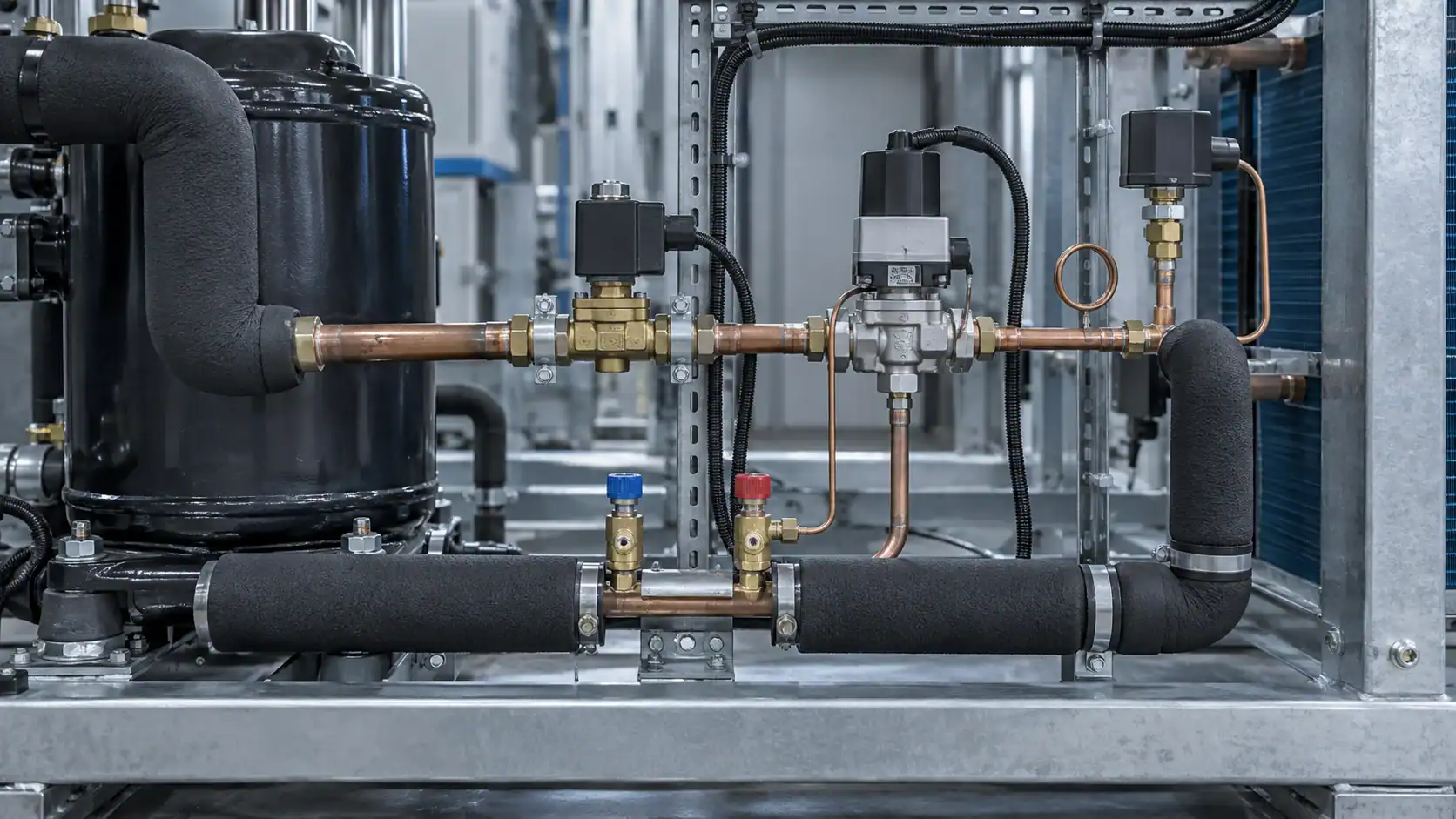
Sensor location should be shown on the drawing. A controller can have the right software and still produce poor results when the probe is mounted in a bypassed air stream, on the wrong side of a coil, or too close to a defrost heater. Danfoss controller documentation gives a practical example of sensor placement, defrost sensing, and relay outputs for refrigeration, defrost, fan, alarm, and light functions.
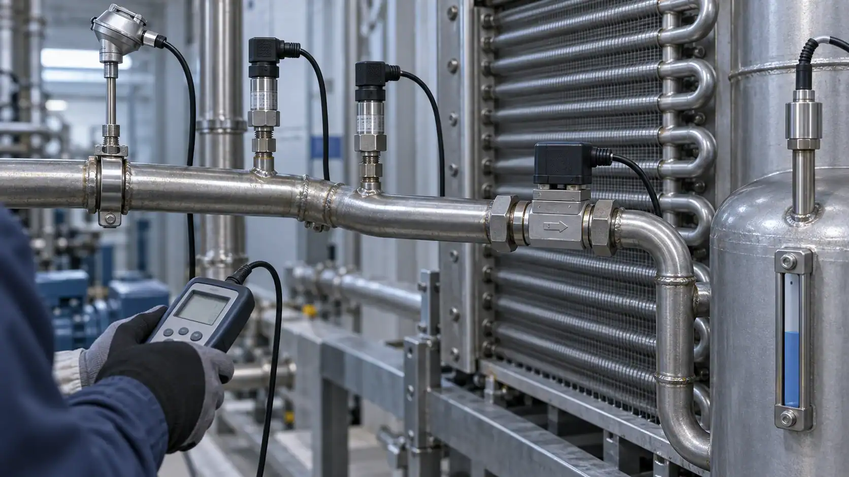
Coordinate compressor, condenser, evaporator, and flow control
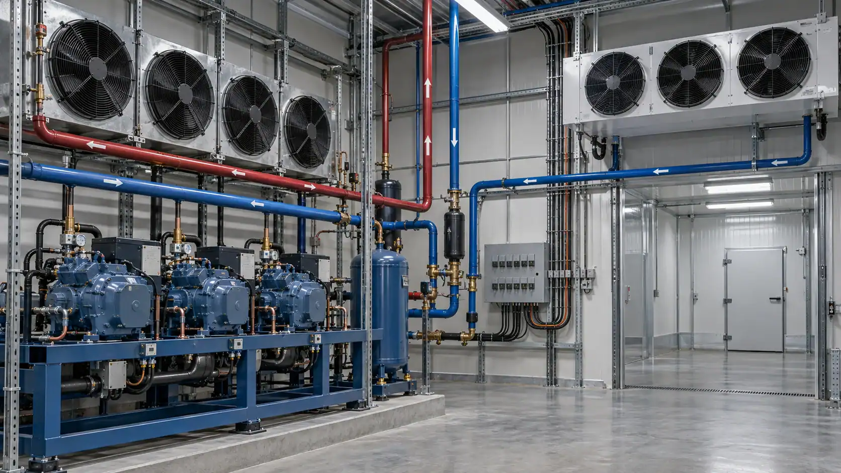
A refrigeration system is a sequence of dependent loads. The compressor cannot be enabled safely when a required oil, pressure, or flow condition is absent. The condenser fan or water valve may need to respond to condensing pressure. The evaporator fan may need a delay after defrost. A liquid-line solenoid, expansion valve, or pump may need to change state before or after the compressor changes state.
| System area | Main control task | Inputs often used | Outputs or actions |
|---|---|---|---|
| Compressor package | Start, stop, stage, unload, or vary capacity while protecting the machine | Suction pressure, room demand, oil pressure, motor status, high pressure, low pressure | Contactor, starter, inverter, capacity solenoid, alarm, shutdown |
| Condenser | Reject heat and maintain a usable condensing condition | Discharge pressure, outdoor temperature, water temperature, flow proof | Fan speed, fan stages, water valve, pump enable, high-pressure trip |
| Evaporator | Maintain the room or process condition and manage frost | Room temperature, coil temperature, suction pressure, door state | Liquid solenoid, expansion valve, evaporator fan, defrost heater |
| Refrigerant flow | Meter, isolate, bypass, or manage liquid and vapor paths | Pressure, temperature, level, demand, defrost state | EEV, TXV, solenoid, EPR, hot-gas valve, pump, receiver valve |
| Common safety | Put the system in a known state during a fault | Pressure limits, sensor failure, flow loss, smoke or leak signal | Shutdown, lockout, alarm, manual reset, remote event |
The system sequence matters more than the label on a single control. When an RFQ includes the sequence of operations, a supplier can identify missing sensors, incompatible outputs, and control dependencies before the panel is wired.
Design defrost and fan sequences together
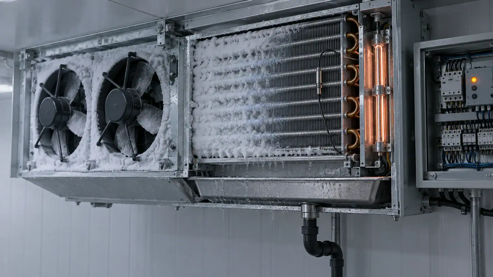
Defrost is a control sequence, not simply a heater rating. The system needs a start condition, an isolation or shutdown action, a termination condition, a drip or delay period when required, and a restart order. The fan may remain off during part of the sequence so warm, wet air does not move into the refrigerated space.
The ASHRAE retail refrigeration guidance lists time-based, pressure-based, temperature-terminated, demand, and proportional defrost approaches. It also describes the role of electronic sensors, alarms, solenoid valves, and rack energy-management control. Choose the sequence from the coil, room, product, refrigerant, moisture load, and operating schedule.
| Sequence stage | Control question | Evidence to include in the specification |
|---|---|---|
| Initiation | What starts defrost: elapsed time, demand, pressure, manual command, or coordinated plant event? | Trigger, schedule, inhibit conditions, and manual override permission |
| Isolation | Which compressor, liquid valve, suction valve, fan, or circuit must change state first? | Valve and motor sequence with expected state feedback |
| Heating or natural defrost | Is the coil defrosted by off-cycle, electric, hot gas, water, or another method? | Heater or valve duty, power, temperature limit, drainage, and safety interlock |
| Termination | What ends defrost: coil temperature, time limit, pressure, or a combination? | Sensor position, termination value range, maximum duration, and fault response |
| Drip and fan delay | How long does the coil remain isolated before airflow restarts? | Delay logic, fan start condition, door or product protection requirement |
| Return to refrigeration | Which valves and compressor commands restore cooling, and in what order? | Restart sequence, minimum off time, alarm delay, and verification record |
Do not copy a default timer into an RFQ without confirming the coil and room. The right termination sensor, fan delay, and alarm inhibit can matter more than a nominal defrost interval.
Treat alarms and fault responses as part of the specification
An alarm is useful only when the system knows the event, the delay, the severity, and the expected response. A high-temperature alarm during pull-down or immediately after defrost may need a delay. A high-pressure trip may need a lockout and manual reset. A failed room sensor may need a defined fallback state rather than uncontrolled compressor cycling.
Define each important alarm with five fields: trigger, delay, action, notification, and reset. Add the normal state of every digital input so an open circuit, broken wire, and normal stop cannot be confused. For connected systems, specify whether the event must be logged locally, sent to a gateway, shown on a panel, or acknowledged by an operator.
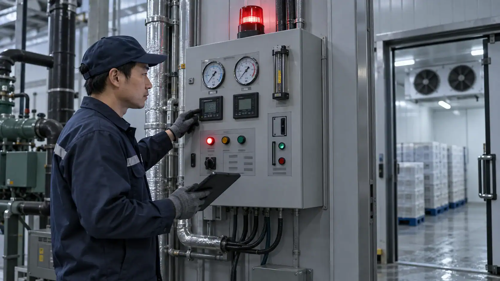
Choose the right local, panel, or supervisory architecture
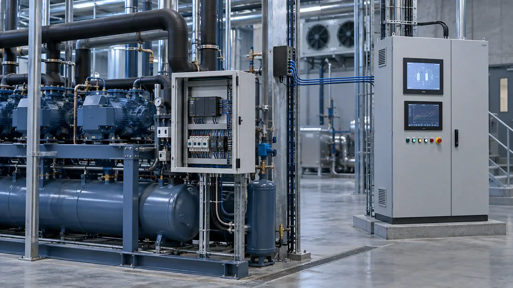
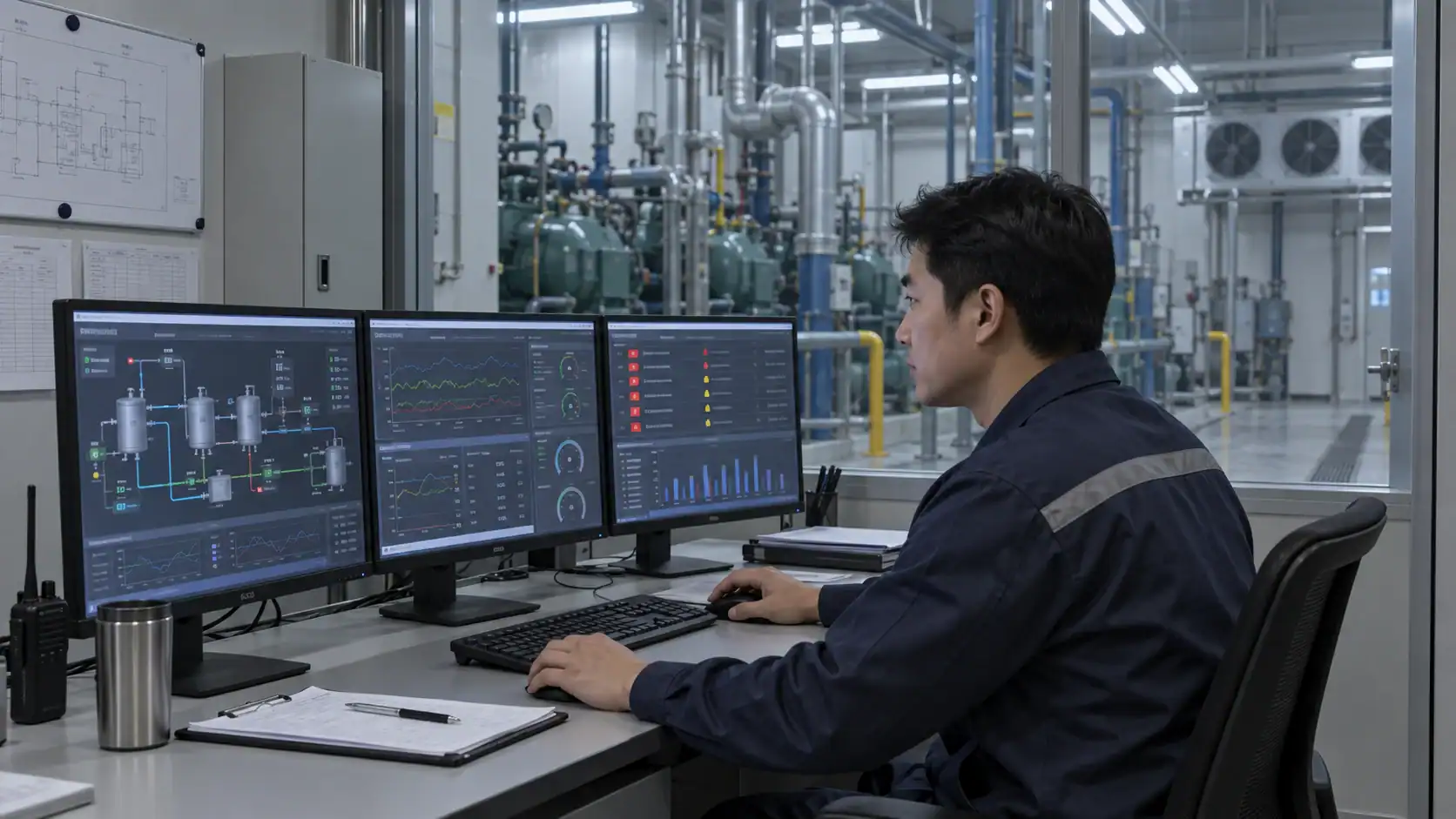
Small equipment may use a local controller with a display and a limited number of relays. A larger installation may use a control panel that combines protection, contactors, relays, drives, terminals, and a controller. A multi-circuit plant may add a supervisory layer that coordinates multiple local controllers and records events.
The boundary matters because a controller is not automatically a panel. A panel is not automatically a plant supervisory system. The Copeland refrigeration controls range illustrates the different scope of general-purpose controllers, multiplexed cabinet controllers, and electronic expansion-valve drivers. Use the refrigeration panel selection guide when the quotation needs an enclosure, incoming power, protection, wiring, and documented I/O rather than a logic device alone.
Consider the following architecture questions:
- Does the local device need to continue safe operation if the network is unavailable?
- Which outputs are direct relay loads, analog signals, pulse signals, or communication commands?
- Is a field service technician expected to adjust parameters locally?
- Which settings need password protection, change logging, or a backup file?
- Which data points must be displayed, trended, exported, or sent as an alarm?
- What happens after power loss, sensor failure, communication loss, or emergency stop?
Build an RFQ that suppliers can actually price
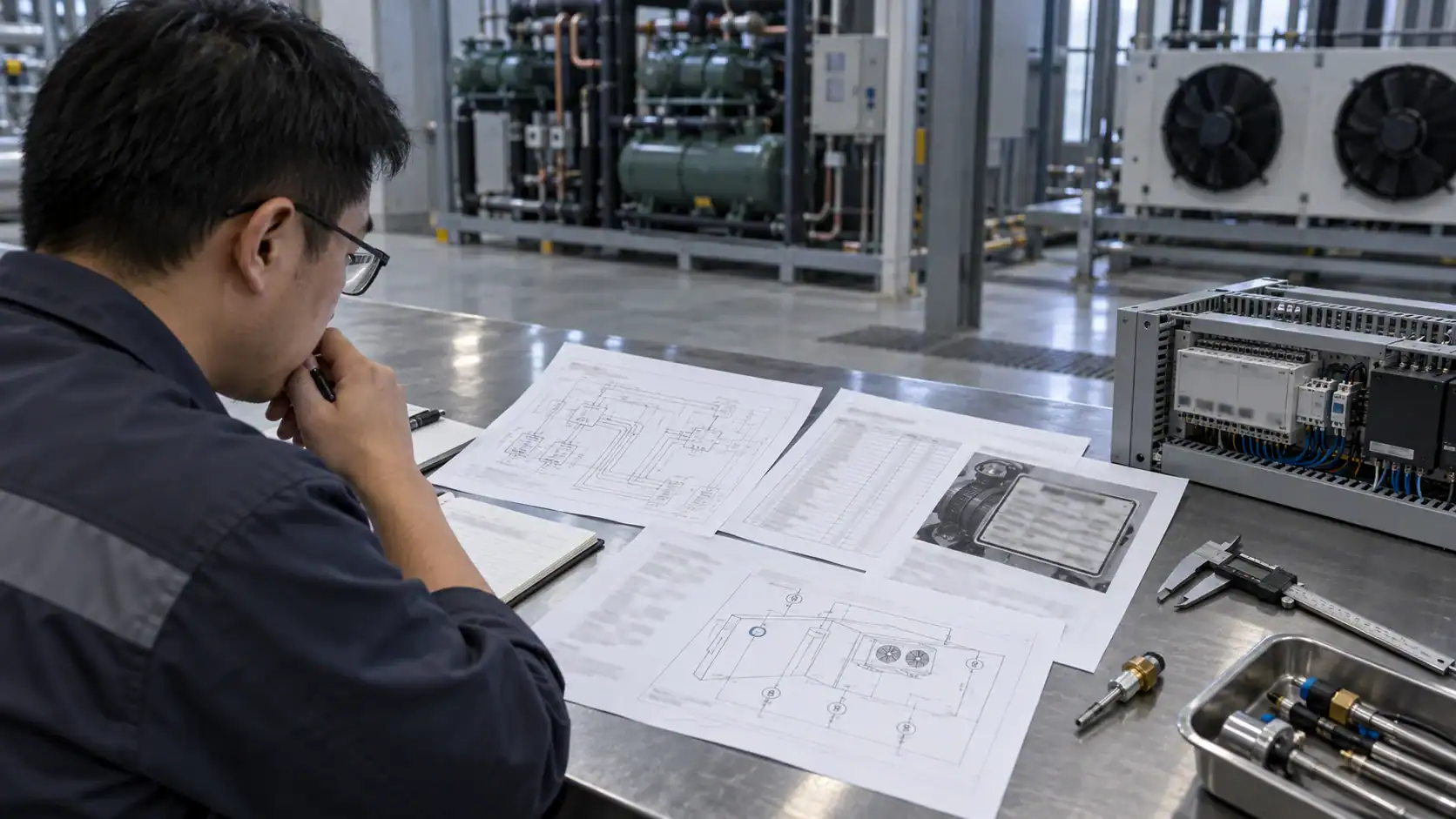
“Need refrigeration controls” is not enough information for a defensible quotation. Send the controlled equipment, the duty point, the I/O list, and the intended sequence. If the design is a replacement, add the original controller, wiring photos, drawing revision, failed symptom, and the parts that will remain in service.
| RFQ item | Minimum information | Helpful evidence |
|---|---|---|
| Application and load | Cabinet, cold room, process skid, rack, chiller, or OEM machine; room or process range; duty point | Equipment layout, product or process description, operating log |
| Refrigeration circuit | Refrigerant, evaporating and condensing conditions, compressor, condenser, evaporator, and expansion device | P&ID, nameplate, selection sheet, piping sketch |
| Measured variables | Sensor type, location, range, accuracy, quantity, and cable or connector requirement | I/O list, sensor photographs, marked-up drawing |
| Outputs and sequence | Compressor, fans, valves, heaters, pumps, lights, alarms, interlocks, and order of operation | Sequence of operations, cause-and-effect matrix |
| Electrical interface | Supply voltage and frequency, phase, current or motor data, relay ratings, analog signal, protocol, and enclosure environment | Panel schedule, motor list, terminal plan, site standard |
| Defrost and alarms | Defrost method, initiation, termination, fan delay, alarm delays, lockouts, reset, and notification | Defrost schedule, alarm list, event history, operating constraints |
| Commercial and quality scope | Quantity, sample need, drawing approval, inspection records, packaging, destination, and documentation | Purchase schedule, inspection plan, shipping and labeling requirements |
If a field is unknown, mark it as unknown and state how it will be measured. A quotation with explicit assumptions is easier to review than a low price built on silent defaults.
Validate drawings, samples, and commissioning records
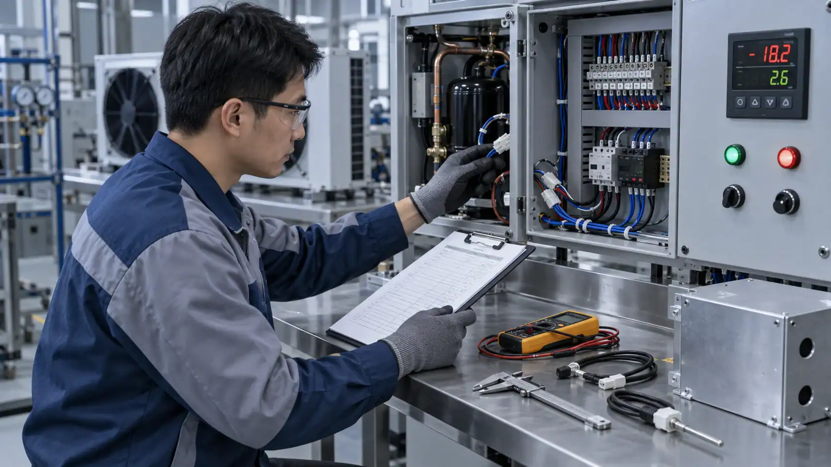
Control verification should follow the sequence, not stop at a power-on check. Review the wiring and I/O list against the approved drawing. Simulate the major sensors and interlocks. Confirm the output changes in the expected order. Then test the fault and alarm paths, including sensor failure, flow loss, door state, pressure trip, defrost termination, power recovery, and communication loss where those functions are included.
| Validation stage | What to check | Release evidence |
|---|---|---|
| Document review | Drawing revision, I/O list, sequence, setpoint ranges, alarm matrix, and component scope | Approved drawing, parameter list, and change record |
| Component inspection | Part identity, sensor type, valve direction, relay or drive rating, enclosure, labels, and terminal numbering | Inspection report, certificates where required, and photographs |
| Dry functional test | Inputs, outputs, interlocks, alarm delays, reset behavior, and safe state without the full thermal load | Test script with expected and actual states |
| System commissioning | Temperature, pressure, flow, defrost, fan, compressor, and restart sequence at the approved duty | Commissioning record with test conditions and instrument references |
| Operations handover | Backup parameters, passwords, alarm recipients, maintenance points, spare list, and revision-controlled documents | Handover pack and operator sign-off |
| Post-start review | Alarm history, sensor drift, nuisance trips, defrost result, and communication reliability | Follow-up log and approved corrective actions |
The ASHRAE and DOE refrigeration commissioning guide frames commissioning as a process that begins with planning and continues through construction, start-up, and operation. Use the same discipline for a control package: acceptance evidence should be agreed before production or installation.
Avoid common control-selection mistakes
The most expensive control errors usually come from an unclear boundary or an incomplete sequence. Watch for these patterns:
- Ordering by controller display or connector shape. Confirm the input range, output type, relay rating, firmware or parameter needs, and sensor compatibility.
- Treating a thermostat as the complete control system. A thermostat may manage one temperature loop while defrost, fan delay, alarms, and compressor protection belong elsewhere.
- Choosing a panel before listing the loads. The enclosure and controller cannot be sized correctly without compressor, fan, heater, pump, valve, and auxiliary current data.
- Leaving sensor locations out of the drawing. The same sensor type can produce a different control result when placed in the wrong air stream or on the wrong coil surface.
- Using time-only defrost without a termination and safety strategy. The coil, room, moisture load, and operating schedule should determine the sequence.
- Sending only the failed part number for a replacement. The failure may be caused by the sensor, wiring, load, pressure condition, or sequence around the device.
- Assuming remote monitoring provides local protection. The equipment should have a defined safe response even when the network or gateway is offline.
- Approving a sample without the sequence test. Dimensions and labels are necessary, but they do not show that the compressor, valves, fans, alarms, and defrost actions happen in the right order.
Use a practical selection sequence
Use this sequence for a new control package, a panel redesign, or a replacement request:
- Define the equipment boundary and identify which components remain in service.
- Record the refrigerant, operating range, design load, ambient or process conditions, and electrical supply.
- Mark every sensor and digital input on the drawing, including the normal state and failure response.
- List every controlled output and write the order of operation for cooling, defrost, alarm, shutdown, and restart.
- Classify each function as operating, primary, limit, interlock, or supervisory control.
- Choose the local controller, panel, rack controller, PLC, gateway, or monitoring layer from the I/O and sequence rather than the brand label.
- Confirm sensor, valve, relay, enclosure, communication, and environmental compatibility.
- Attach the RFQ evidence, state unknowns, review the supplier drawing, and agree the sample and commissioning tests before release.

The refrigeration controller guide is useful when the requirement narrows to a controller. For a complete system, keep the controller discussion connected to the matched compressor, coils, fans, valves, panel, and operating conditions.
Frequently asked questions
What are refrigeration controls?
Refrigeration controls are the devices and logic that measure temperatures, pressures, levels, flow, equipment status, and safety conditions, then command or protect compressors, condensers, evaporators, valves, fans, defrost hardware, pumps, and alarms. The term can describe a single switch, a local controller, a complete panel, or a supervisory system, so the equipment boundary should be defined before ordering.
What are the main types of refrigeration controls?
The main functional groups are operating controls, primary controls, limit controls, interlocks, and supervisory controls. In a practical system, these functions may be performed by thermostats, pressure switches, transducers, electronic controllers, expansion-valve drivers, contactors, relays, PLCs, panels, gateways, and monitoring software.
How do refrigeration controls manage defrost?
The control sequence initiates defrost, changes the required valves and compressor or fan states, runs the selected defrost method, terminates from temperature, pressure, time, or a combination, applies a drip or fan delay when required, and then restores refrigeration. The coil, room, moisture load, refrigerant, and operating schedule determine the appropriate sequence.
What information is needed for a refrigeration controls quote?
Send the application, refrigeration circuit, refrigerant, operating conditions, controlled variables, sensor locations, I/O list, electrical supply, load ratings, sequence of operations, defrost method, alarm matrix, communication protocol, enclosure environment, quantity, drawing revision, and required inspection or commissioning records. Photos and the original nameplate help when the request is a replacement.
Can a refrigeration controller replace a refrigeration panel?
Usually not by itself. A controller provides logic and selected outputs, while a panel may also include the enclosure, disconnect, protective devices, contactors, drives, terminal blocks, wiring, grounding, labels, and service provisions. Confirm whether the RFQ is for a logic device, a wired panel, or a complete controls package.
How should a refrigeration controls sample be tested?
Review the drawing and I/O list, verify component identity and ratings, simulate sensors and interlocks, check output order, test alarm delays and resets, verify defrost termination and fan restart, check power recovery and communication behavior where included, and record the test conditions. Approve the sample against the sequence and safety requirements, not only its dimensions.
Send the control scope with the equipment duty
A refrigeration controls quotation is easier to review when the I/O list, sequence of operations, equipment duty, drawing revision, and installation conditions arrive together. Domi can review the control boundary with the matched coils, compressor, fans, valves, panel, and operating conditions before a technical quotation is prepared.