Short answer: choose a refrigeration thermostat from the controlled load, temperature range, sensor location, differential, probe type, electrical contact rating, defrost method, compressor protection and installation environment. A thermostat may simply cycle a compressor from sensed temperature, or it may be part of an electronic controller that also manages fans, defrost, alarms and communications. Confirm the boundary before ordering a replacement or pricing an OEM assembly.
What a refrigeration thermostat controls
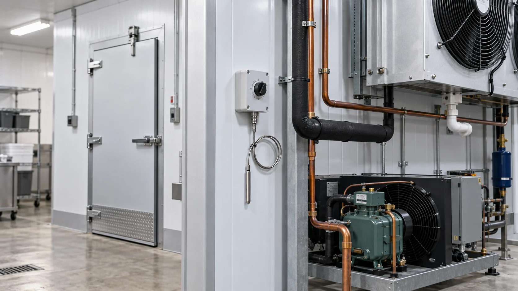
A refrigeration thermostat is a temperature-driven control device. It compares a sensed condition with a setpoint, then changes an output when the temperature reaches a cut-in or cut-out point. In a small cabinet, that output may switch a compressor contactor directly. In a walk-in cooler, it may send a demand signal to a liquid solenoid or a refrigeration controller. In an OEM machine, it may be one input in a larger control sequence.
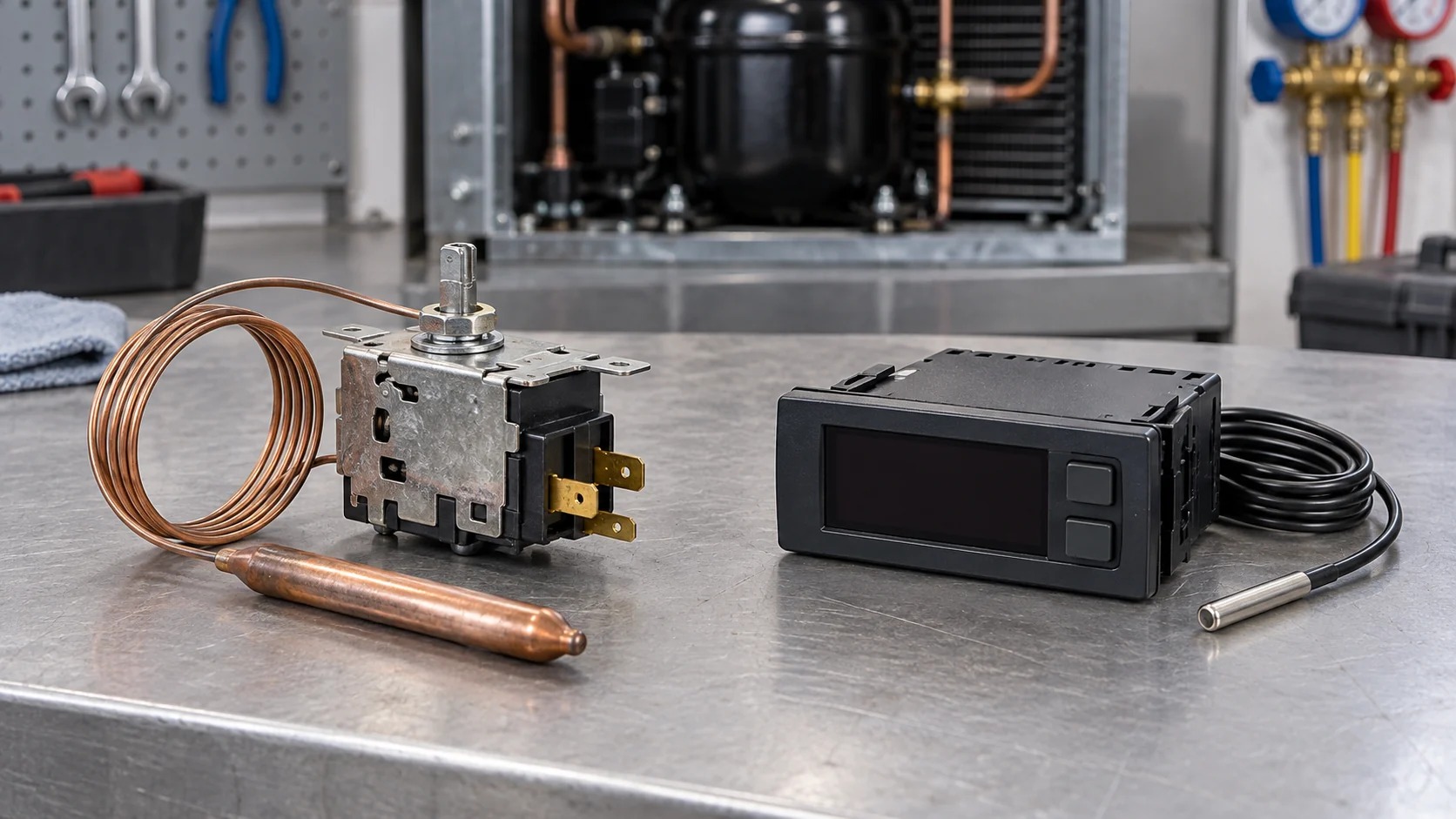
The word thermostat does not tell a buyer how much of the system is included. A mechanical cold control can contain a capillary tube and switching contacts. An electronic thermostat can add a probe, display, adjustable differential, alarm and relay outputs. A refrigeration controller can add defrost, fan delay, minimum off time, sensor-failure handling and communications. A refrigeration panel adds the enclosure, protection, terminals and wiring around those devices.
Danfoss describes electronic temperature controls across commercial refrigeration applications such as cases, cold rooms, trucks and dryers, with separate functions for temperature, compressor, condenser, evaporator and defrost management. The Danfoss electronic temperature control range is a useful reference for the difference between a thermostat function and a broader controller platform. Do not assume that a feature shown on a controller page is present in a simple thermostat replacement.
| Control boundary | What it normally does | What the buyer must confirm | Common mismatch |
|---|---|---|---|
| Mechanical thermostat | Senses air or coil temperature and switches a circuit | Sensing bulb, capillary length, range, differential, contact rating and mounting | Ordering by appearance without checking the sensing range or contacts |
| Electronic thermostat | Uses a probe and logic to switch a relay or demand output | Probe type, input range, setpoint, differential, output mode, power and alarm behavior | Replacing a controller with a thermostat that cannot manage defrost |
| Refrigeration controller | Coordinates temperature, defrost, fans, alarms and compressor timing | Full sequence, sensor count, outputs, parameters, communication and backup | Calling a programmable controller a drop-in thermostat |
| Refrigeration panel | Houses power protection, terminals, controls and field wiring | Supply, motor loads, enclosure, I/O, isolation, drawings and testing | Pricing the panel while excluding the thermostat or field sensor |
Use Domi’s refrigeration controller selection guide and refrigeration panel selection guide as adjacent references. The thermostat article owns the sensing and temperature-control decision, while those pages cover broader logic and electrical assembly scope.
Choose mechanical, electronic or programmable control
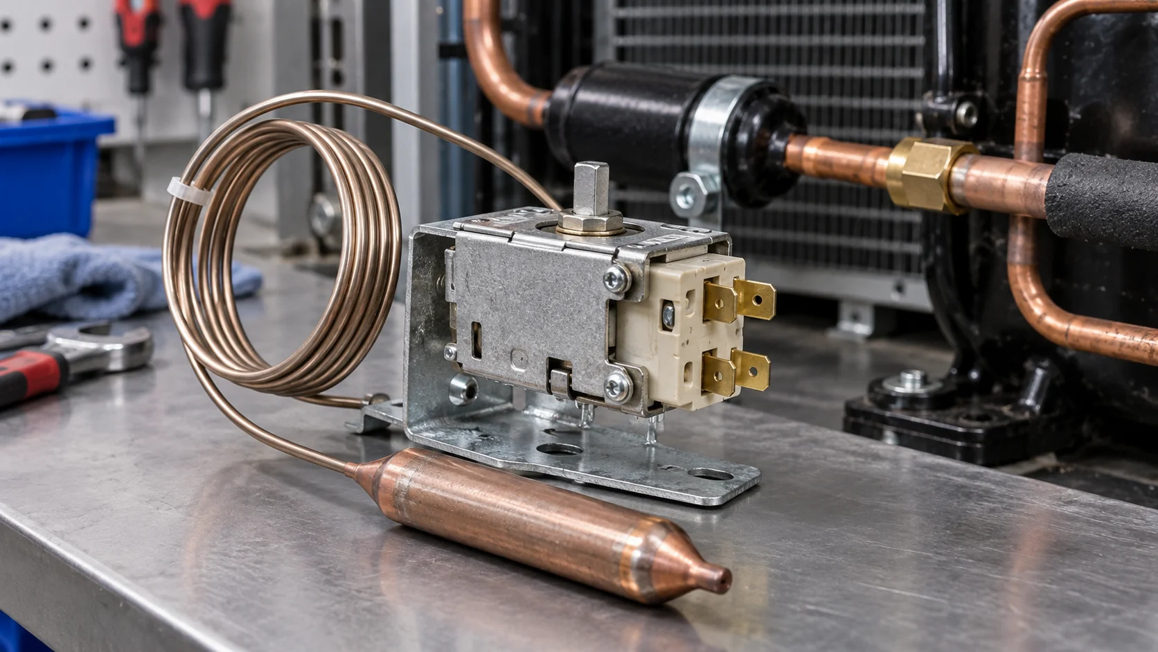
Mechanical thermostats can be appropriate for simple, stable applications where a single temperature input and a straightforward contact are all that is required. They are familiar to service teams and can be useful in a compact cabinet or as a limit device. Their limitations are equally practical: the capillary must be routed without damage, the sensing bulb must sit in the correct air or coil location, and the switching contacts must suit the load or an intermediate relay.
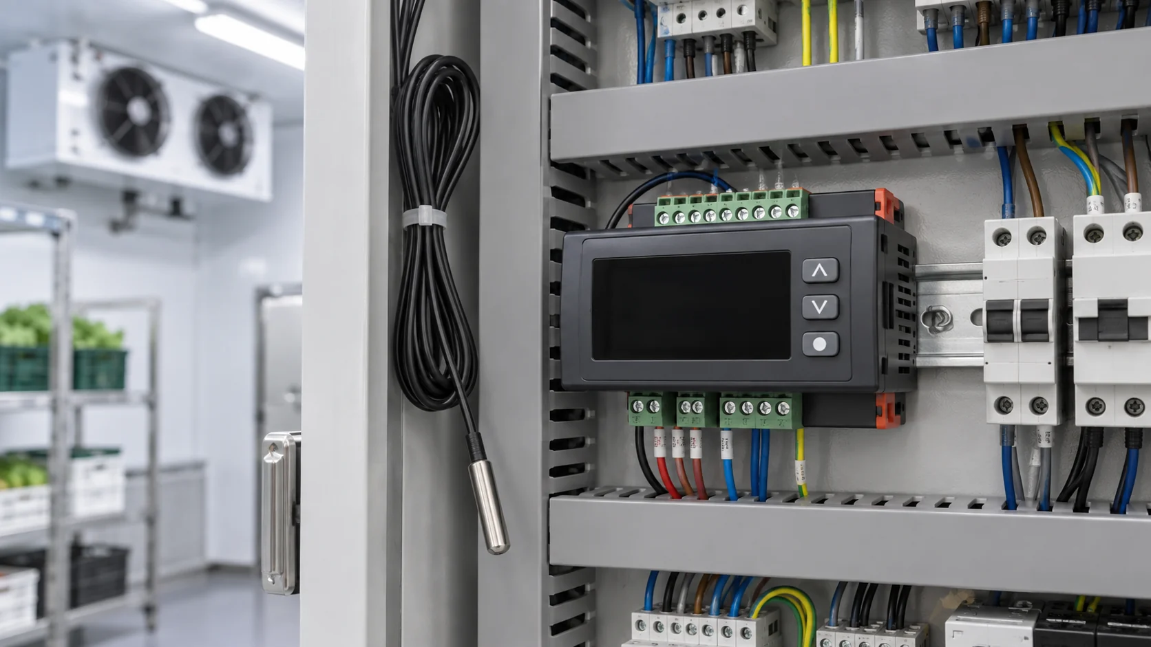
Electronic thermostats are usually easier to adjust and can use a replaceable probe rather than a long capillary. They may provide a visible setpoint, a configurable differential, high or low temperature alarms and a relay output. They still require careful selection. A probe with the wrong resistance curve, an output that cannot handle the contactor coil or a controller that lacks the required defrost mode will create a commissioning problem even when the mounting cutout fits.
Programmable refrigeration controllers are justified when the sequence includes multiple sensors, defrost termination, fan delay, minimum compressor off time, lead-lag logic, remote alarms or a network connection. They are not automatically better for a basic cabinet. More parameters mean more opportunities for an incorrect setup, so request a saved parameter list and a point-by-point commissioning record.
| Selection situation | Mechanical thermostat | Electronic thermostat | Programmable controller |
|---|---|---|---|
| Small reach-in cabinet | Often sufficient if the load is simple | Useful when a probe and display improve service | Usually more capability than needed |
| Walk-in cooler | Possible for a basic demand circuit | Common when defrost, alarms or fan delay are required | Suitable for multiple evaporators or remote monitoring |
| Low-temperature freezer | Must be rated for the actual range and defrost environment | Useful when sensor failure and defrost logic need visibility | Best when the sequence has several safeties and timed stages |
| OEM machine | Works when the machine interface is fixed and repeatable | Good for configurable variants and service replacement | Best when software, network and multi-load sequencing are part of the design |
Match sensor location, range and differential
The sensing location often matters more than the thermostat brand. A return-air probe responds to the air entering the evaporator and can represent the room or cabinet average. A product-zone probe can protect a stored product temperature but may react slowly. An evaporator probe can support defrost termination or coil protection, but it should not be treated as a room-temperature measurement. Put the intended location, mounting method and cable path in the RFQ.
Avoid placing a probe against a cold metal surface, in a direct fan discharge, beside a door leak or where water can collect unless that is the specified measurement. For a capillary bulb, secure the bulb without crushing the tube and keep it away from heaters. For an electronic probe, protect the cable from sharp sheet metal, high-voltage wiring and excessive moisture. If the system has more than one sensor, assign each sensor a name and a failure action.
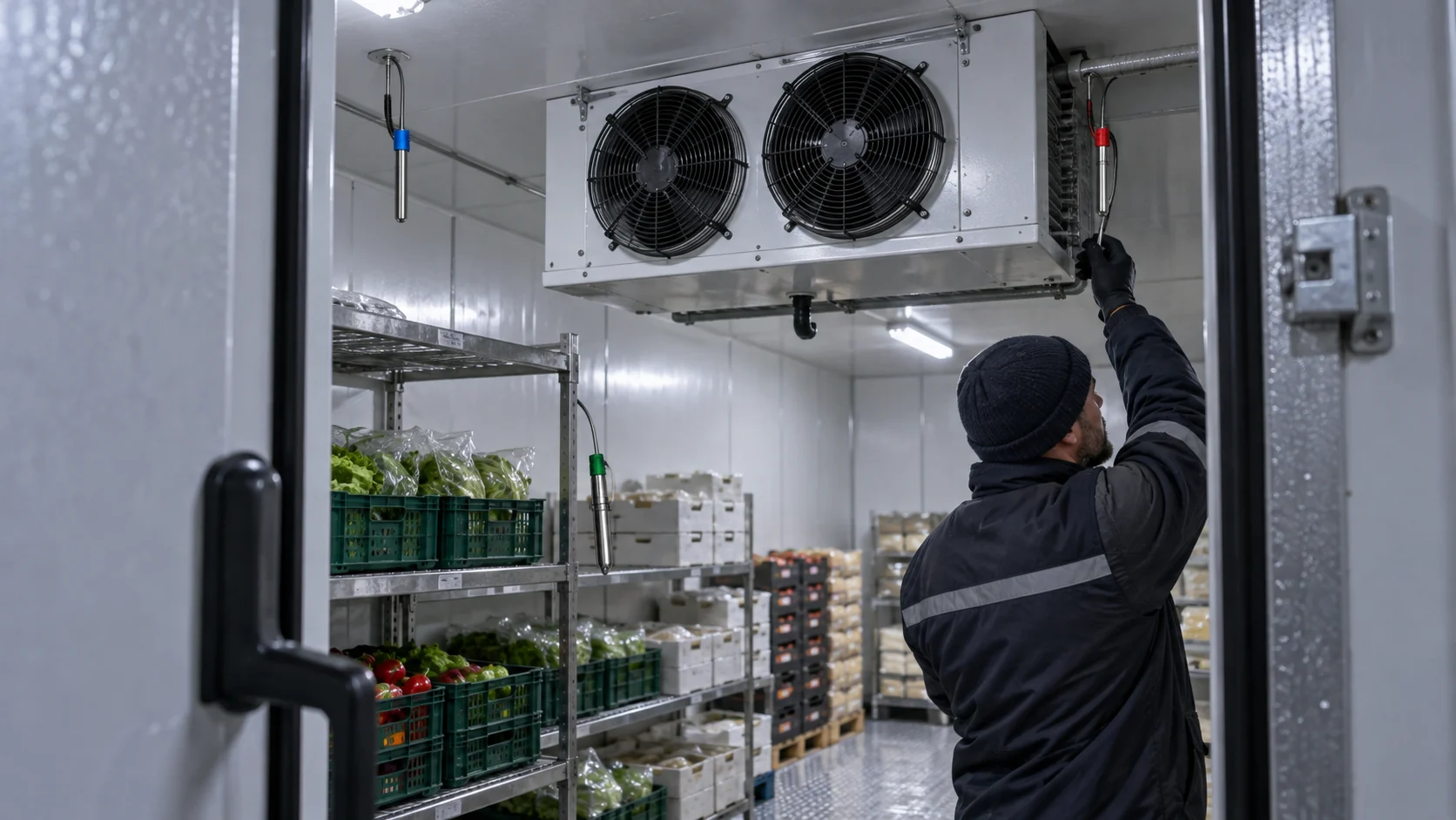
Setpoint is only one part of the control decision. The differential, sometimes called the deadband, determines how far the temperature must move before the output changes again. A differential that is too narrow can cause short cycling. One that is too wide can create unacceptable product swings. The correct value depends on the load, sensor position, compressor minimum off time, evaporator response and the permitted temperature band.
Choose a range that covers the actual operating point while leaving adjustment room for commissioning. Do not select a very broad range just because it appears more flexible. A broad range can reduce resolution, make accidental changes more serious and hide a wrong probe. Record cut-in, cut-out, alarm and restart values separately.

Apply the thermostat to the real refrigeration load
Commercial equipment is not one uniform application. A reach-in refrigerator, a glass-door display case, a walk-in cooler and a low-temperature freezer can all use a thermostat, but their air movement, load pattern, defrost method and service access differ. ENERGY STAR’s commercial refrigerator and freezer guidance provides useful equipment context. Use the actual cabinet or room duty, not a generic product category, when selecting the control.
Walk-in coolers
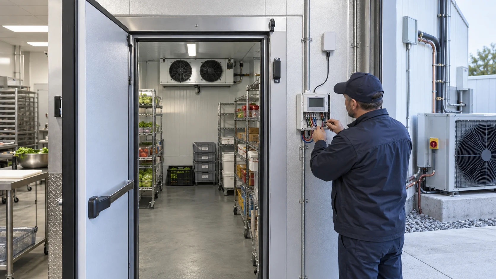
For a walk-in cooler, record room setpoint, expected product load, door traffic, evaporator fan behavior, defrost method, drain heater, door switch and the location of the room sensor. A thermostat may call for cooling through a liquid solenoid while a separate controller handles compressor protection. If the thermostat output switches a contactor directly, verify coil voltage, inrush and the required isolation.
Copeland room controllers describe control of compressors, fans, defrost, lights and alarms for cold-room applications. The Copeland room-controller reference helps frame the difference between a simple temperature call and a complete room sequence.
Display cases and foodservice equipment
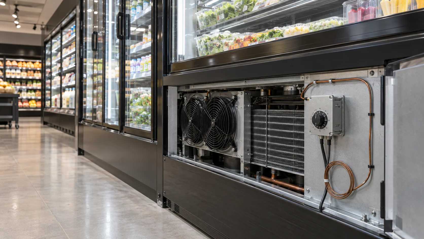
Display cases can have several air paths and a fast-changing product load. The probe should measure the intended control point without being fooled by a discharge jet, lighting heat or a door opening. Confirm whether the thermostat is controlling one case, a group of cases or a networked controller. A replacement part should match the original sensor curve and output wiring, not just the front-panel shape.
Freezers and low-temperature systems
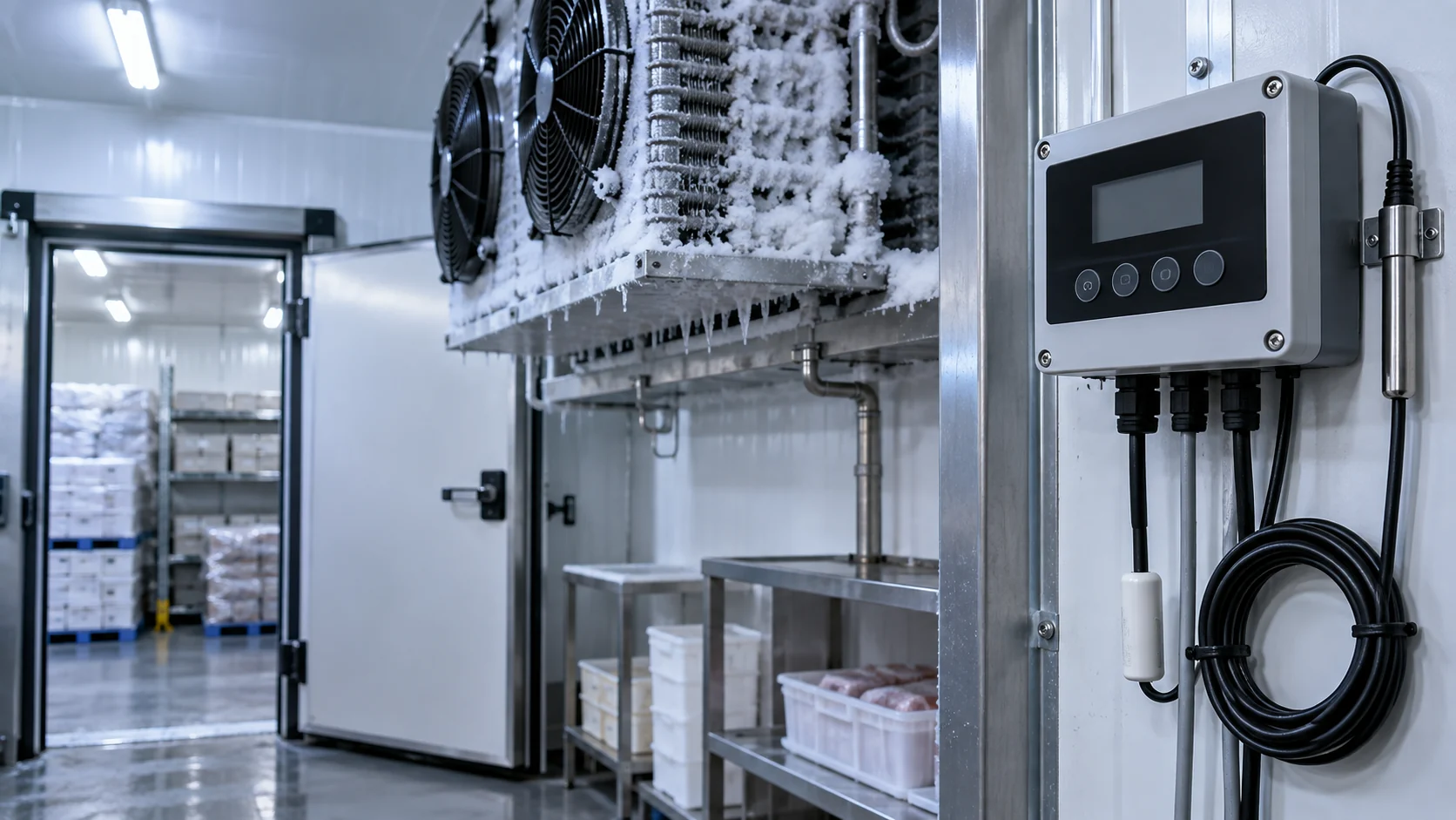
Freezer applications add frost, defrost heat, lower ambient temperatures and longer pull-down periods. Confirm that the thermostat or controller is rated for the sensor environment and that its output is coordinated with defrost termination, fan delay and compressor restart. A room thermostat should not be used as a defrost safety limiter unless the design specifically assigns that function.
| Application | Primary sensing point | Functions to coordinate | Evidence to request |
|---|---|---|---|
| Reach-in refrigerator | Cabinet air or return air | Compressor demand, door heat and alarm | Cut-in and cut-out test at the installed probe |
| Walk-in cooler | Room return air or defined product zone | Liquid solenoid, evaporator fans, defrost and door switch | Sensor placement drawing and defrost sequence test |
| Display case | Case return air or product protection point | Fan airflow, lighting heat, alarms and compressor timing | Stable-temperature test under representative loading |
| Low-temperature freezer | Room air plus evaporator or defrost sensor | Electric or hot-gas defrost, fan delay and restart protection | Defrost termination and post-defrost recovery record |
| OEM equipment | Defined machine reference point | Full interface, variant parameters and service replacement | I/O map, parameter backup and compatibility statement |
Coordinate defrost, fan operation and compressor protection
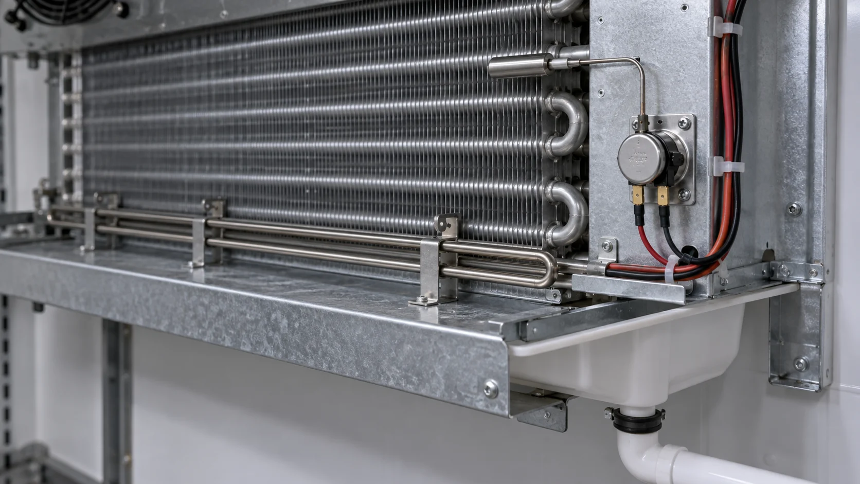
A thermostat demand is not the entire refrigeration sequence. During defrost, the compressor may stop, a heater or hot-gas valve may operate, fans may wait for a safe coil temperature and a drain heater may prevent refreezing. The thermostat must either hand off to a controller or follow a documented sequence. A simple thermostat that closes its contact during defrost can defeat the intended safety logic.
Defrost thermostats or limit devices are commonly used to terminate or protect a heater cycle. The KE2 low-temperature control reference illustrates how thermostat, defrost timing and fan delay can be combined in a walk-in application. Treat any product feature as a scope example, then confirm the actual sequence for the equipment.
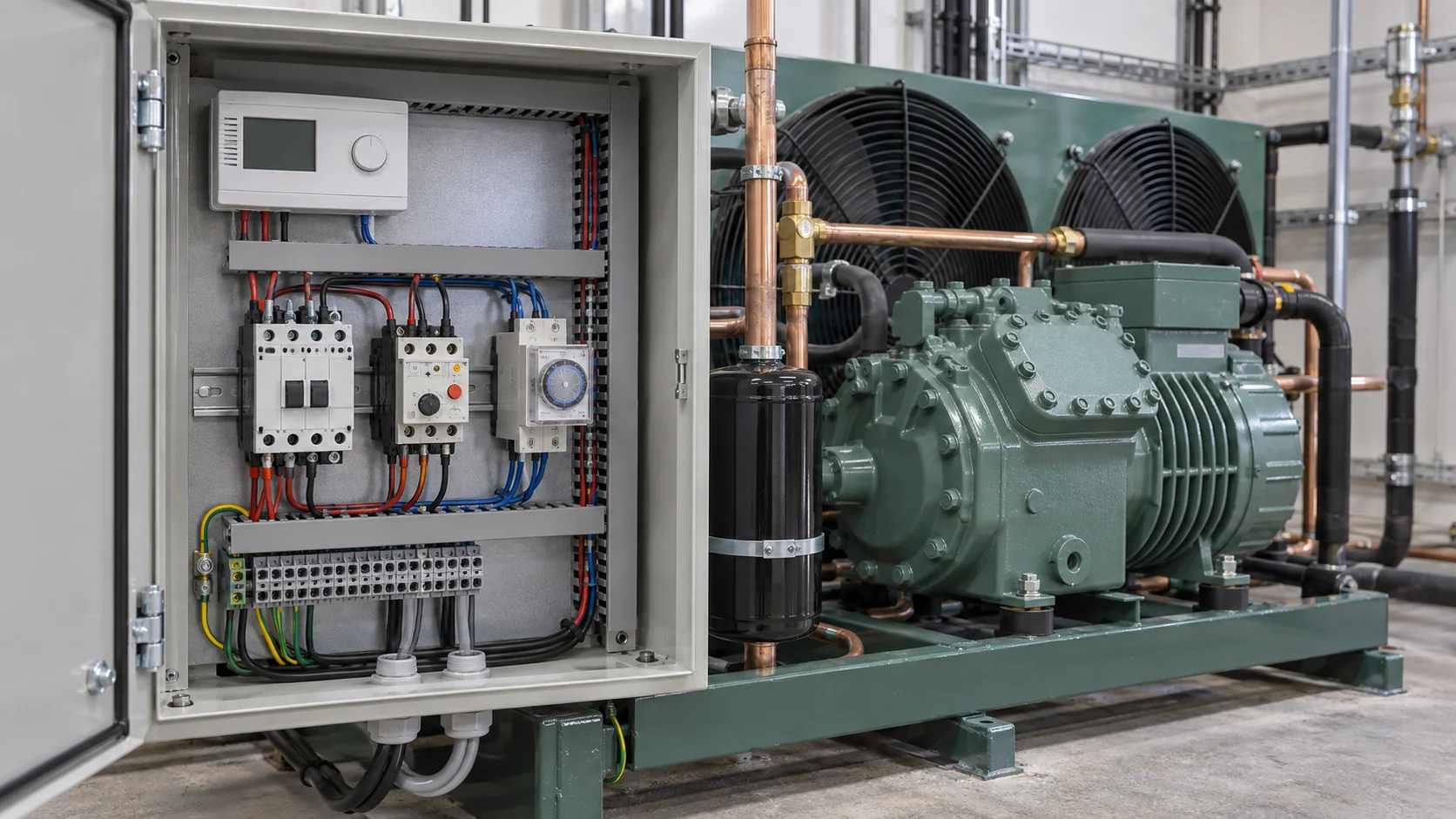
Compressor protection is another boundary to make explicit. The thermostat may switch a control relay, while the panel or compressor controller enforces minimum off time, high-pressure cutout, low-pressure cutout, overload reset, oil protection and restart delay. If the thermostat contact carries a motor circuit directly, confirm the motor starting conditions and contact life. If it only sends a low-voltage demand, confirm the receiving input and its fail-safe state.
PENN’s field and cold-room controller information shows why fan operation, defrost, alarms and diagnostics should be considered alongside temperature regulation. Keep the thermostat function, controller function and panel protection visible in the wiring diagram.
Verify electrical, enclosure and compatibility details
Check the thermostat supply voltage, sensing input, output type, contact rating, terminal arrangement and enclosure environment. A relay output may be normally open, normally closed or changeover. A solid-state output may require a defined load or polarity. A sensor input may require a specific resistance curve or a current or voltage range. These details are not interchangeable across brands.
For a replacement, photograph the nameplate, terminals, mounting cutout, probe, capillary routing and nearby wiring before removing the old part. Record the old setpoint, differential, alarm values and defrost relationship. If the original part number is unavailable, dimensions alone are not enough. The buyer should provide the model, serial information, refrigerant or application, voltage, sensor type and the symptom that triggered the replacement.
Select the enclosure and cable protection for the site. A washdown food plant, a dry machine room, an outdoor condensing unit and a cold-room exterior wall have different moisture, corrosion, temperature and service-access risks. Keep probe cables separated from high-voltage conductors where required, provide strain relief and avoid a cable path that creates a false temperature reading.
Commission and maintain the control
Commissioning should verify the installed sensor, not only the thermostat menu. Compare the probe with a calibrated reference, confirm the measured location, test cut-in and cut-out, observe the compressor or demand output, and record the actual differential. Then test defrost, fan delay, alarm thresholds, restart protection and sensor-failure behavior as applicable.
Record the final setpoints, parameter file, wiring revision, probe identification, output state and test result. Mark the thermostat location on the as-built drawing. During service, inspect capillary damage, probe drift, loose terminals, moisture entry, crushed cables and changes to the evaporator or product load. If the coil, fan or defrost method changes, revisit the thermostat location and differential rather than assuming the old settings still fit.

For projects that combine thermostat changes with a new evaporator or condenser duty, use Domi’s engineering capabilities to review the drawing and operating point, and its testing lab page to frame documentation and verification questions. These links do not imply that Domi supplies every thermostat model.
Prepare a replacement or OEM thermostat RFQ
An RFQ should let the supplier determine compatibility without guessing. Include the equipment model, application, refrigerant, target temperature, allowable band, sensor location, defrost method, compressor interface, supply voltage, output circuit, enclosure location, probe length, connector, mounting method, quantity and required documentation.
For an OEM build, add the control narrative, I/O map, parameter defaults, alarm strategy, service replacement part, packaging, sample requirement and change-control process. If the thermostat affects coil selection, include the evaporator or condenser duty, airflow, fin spacing, fluid conditions and connection details. Domi’s custom coil fabrication path is relevant when a thermostat change is part of a wider thermal-component redesign.

| RFQ field | Information to send | What the supplier should return |
|---|---|---|
| Application and duty | Cabinet or room type, target temperature, load pattern and ambient | Recommended control type and stated operating limits |
| Sensor and probe | Air, product, coil or defrost point; probe curve, length and mounting | Compatibility statement, probe drawing and replacement part |
| Electrical interface | Supply, output type, contactor or relay coil, protection and isolation | Terminal diagram, contact rating and wiring assumptions |
| Sequence | Cut-in, cut-out, differential, defrost, fan delay, alarm and restart rules | Parameter list and functional sequence |
| Environment | Indoor, outdoor, washdown, cold-room wall, vibration and cable route | Enclosure or mounting recommendation and installation notes |
| Verification and delivery | Sample, FAT or bench test, drawings, software backup, packaging and quantity | Test record, documents, lead time, MOQ and deviation list |
Ask for a compatibility review before ordering a visually similar part. Use the specific CTA contact Domi for a technical review when the thermostat change is connected to a coil, condenser, evaporator or OEM drawing. Request the supplier to confirm testing, documentation, MOQ and lead time in writing.
Frequently asked questions
Is a refrigeration thermostat the same as a refrigeration controller?
No. A thermostat is primarily a temperature-driven control function. A refrigeration controller can add defrost, fan delay, alarms, sensor-failure logic, minimum compressor off time and communications. Some electronic products combine both roles, so compare the actual inputs, outputs and sequence rather than the product name.
How do I choose the correct refrigeration thermostat range?
Start with the actual cabinet, room or product temperature and the allowed operating band. Confirm the probe location, sensor curve, differential and alarm limits, then choose a range that covers commissioning without inviting accidental settings. The range must also suit the freezer or cooler environment and the defrost sequence.
Can a thermostat switch a compressor directly?
Sometimes, but only when the thermostat contact rating, motor starting conditions, protection, isolation and local design allow it. Many systems use the thermostat as a low-voltage demand signal while a contactor, panel or controller handles motor protection and restart timing. Put the interface in the wiring diagram.
Where should a refrigeration thermostat probe be installed?
Install it at the defined control point, such as return air, a product zone or an evaporator location, and protect it from direct discharge air, heaters, water and damaged cable routing. The correct location depends on the control objective. Record it on the drawing so a service replacement does not move the sensor.
Does a refrigeration thermostat control defrost?
A simple thermostat usually does not control a complete defrost cycle. A refrigeration controller may coordinate defrost initiation, heater or hot-gas output, termination sensor, drain heater and fan delay. A separate thermostat or limiter may protect the evaporator or terminate electric heat. Confirm which device owns each function.
What should I send when requesting a replacement thermostat?
Send the equipment model and serial information, old part number, photos of terminals and mounting, probe or capillary details, supply voltage, output circuit, target temperature, differential, defrost method and the failure symptom. Dimensions alone cannot confirm compatibility. Ask for a written deviation list if the proposed part is not an exact replacement.