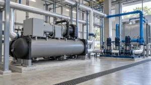
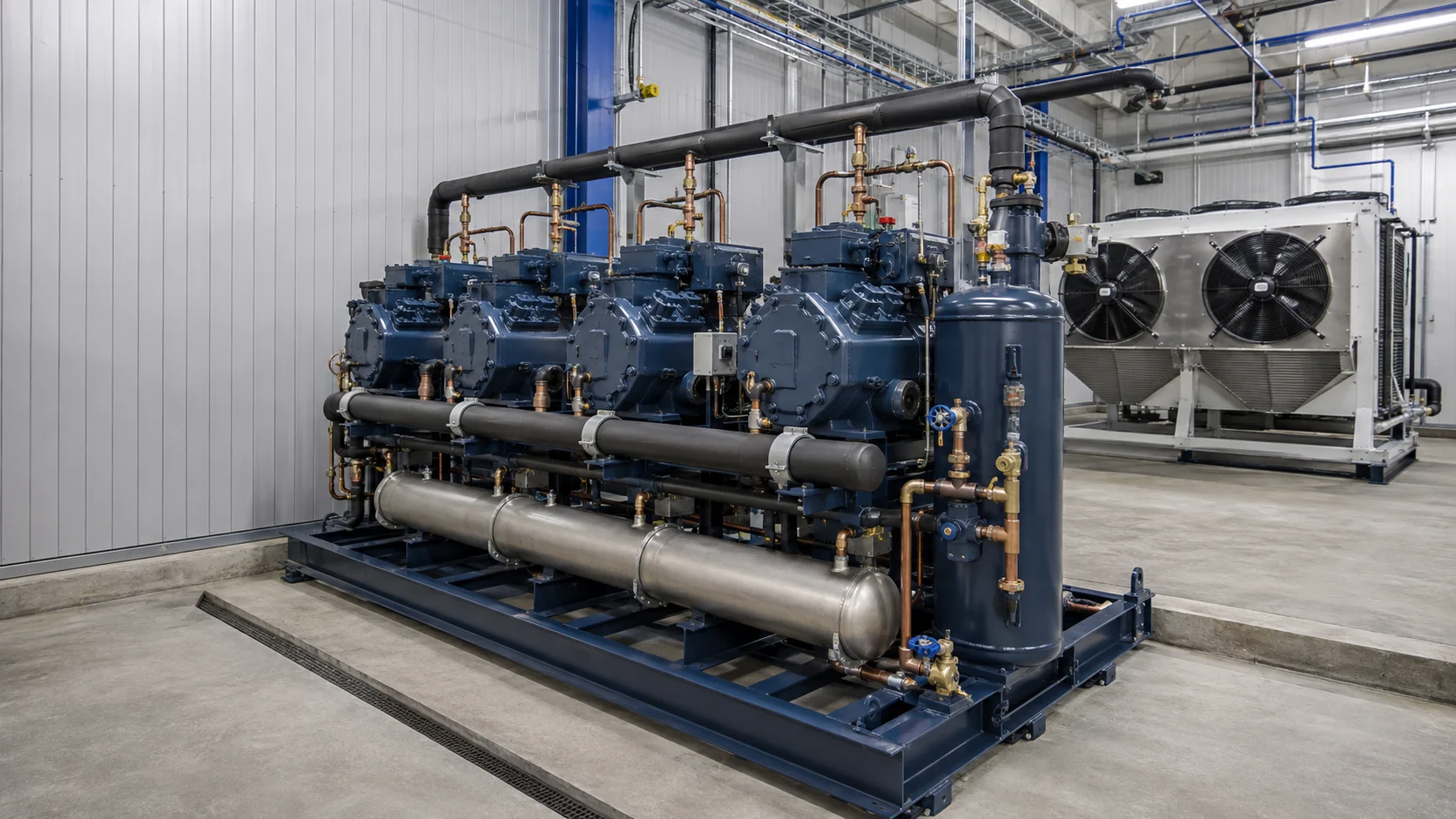
A refrigeration rack is a centralized system that connects two or more compressors in parallel to serve several refrigerated cases, walk-ins, or freezer circuits. The right rack matches the connected load, suction groups, refrigerant, condenser, oil return, controls, service access, and future capacity plan. Treat it as a complete plant package, not as a frame with a few compressors attached.
What is a refrigeration rack?
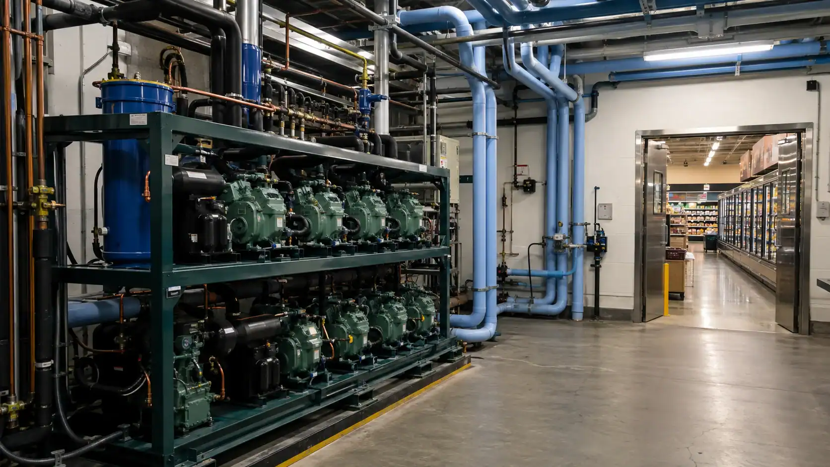
A refrigeration rack collects the compressor and common refrigerant-side hardware in one serviceable assembly. Each compressor connects to a suction header and a discharge header. The suction header receives vapor from multiple evaporator circuits. The compressors raise the vapor pressure, the condenser rejects heat, and the liquid header sends refrigerant back to the cases through expansion devices.
The arrangement suits supermarkets, food distribution centers, process rooms, and other sites with several loads that run at different times. One compressor can run during a light load. More compressors can stage on as the load rises. That is the practical reason to use a rack: capacity follows the connected load more closely than a bank of unrelated condensing units.
The rack itself does not define the whole refrigeration system. Evaporator coils, electronic or thermostatic expansion valves, liquid-line solenoids, defrost hardware, condenser fans, piping, controllers, and safety devices all affect the result. The parts of a refrigeration system guide is useful when an RFQ needs a common vocabulary for those connected components.
How a rack refrigeration system moves refrigerant
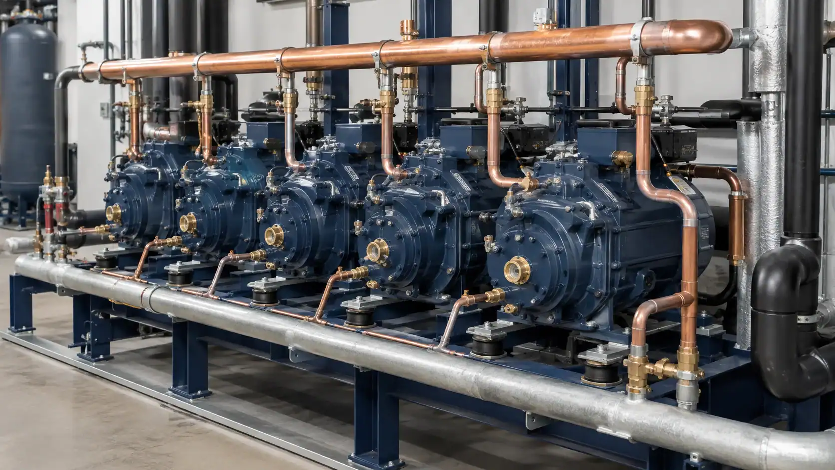
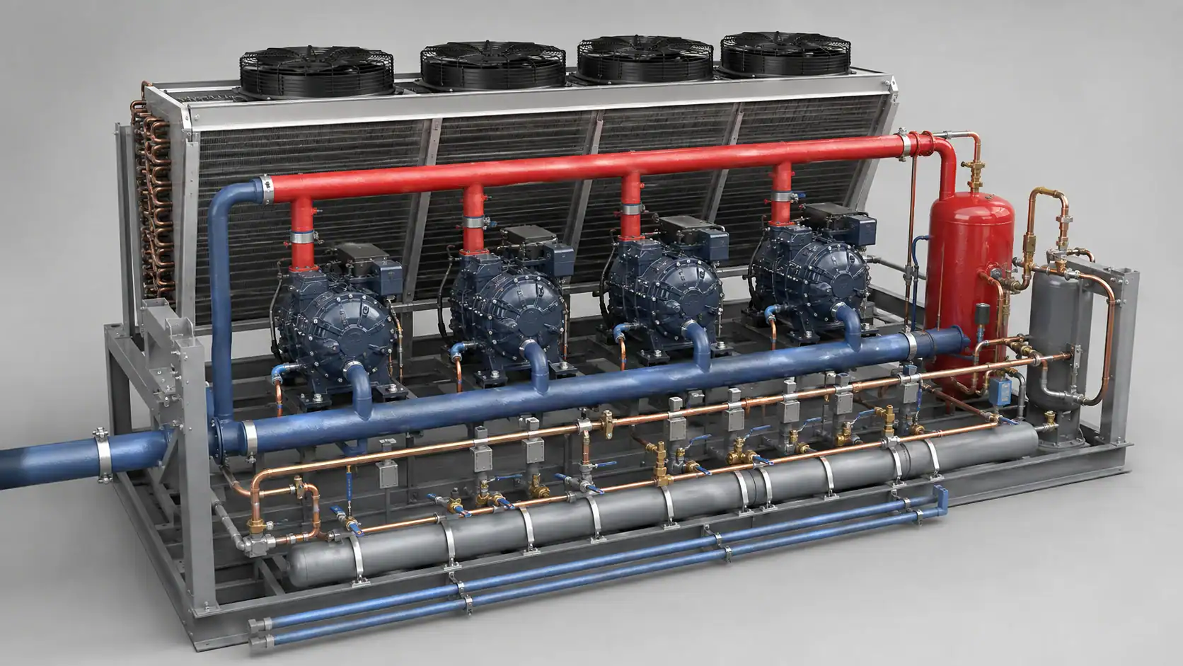
The operating sequence is easier to understand when the headers are followed in order. The exact valves and controls depend on the refrigerant and the rack design, but the flow path normally contains these functions.
| Rack component | What it does | Buyer checks before approval |
|---|---|---|
| Suction header | Collects low-pressure vapor from the connected evaporators or cases | Header size, oil return, suction groups, insulation, service valves |
| Parallel compressors | Raise vapor pressure and stage capacity to match demand | Operating envelope, motor voltage, minimum run time, capacity steps |
| Discharge header | Combines compressor discharge gas before heat rejection | Vibration support, check valves, discharge temperature protection |
| Condenser and fans | Reject heat and condense refrigerant to liquid | Design ambient, airflow, fan control, coil material, fouling access |
| Receiver and liquid header | Store and distribute liquid to several circuits | Receiver volume, relief protection, subcooling basis, isolation valves |
| Oil management | Separate, store, and return oil to the compressors | Separator type, reservoir level control, oil differential protection |
| Controls and safeties | Coordinate staging, pressure limits, alarms, and shutdowns | Sensor range, fail-safe state, communications, parameter backup |
Suction header and compressor staging
The suction header should present a stable pressure to each compressor while allowing oil to travel back to the oil separator or compressor crankcases. A header that is too small raises pressure drop. A header that is arranged poorly can trap oil or create uneven flow into the compressor inlets. Include the design suction pressure, expected vapor velocity, pipe sizes, and branch geometry in the engineering review.
Compressors may stage in fixed steps, use variable-speed drives, or combine a variable compressor with fixed machines. The control strategy should define the lead compressor, rotation schedule, minimum run time, minimum off time, and the response when a compressor trips. A rack with a large nameplate capacity can still cycle badly if the smallest available step is much larger than the night load.
Discharge, condenser, and liquid side
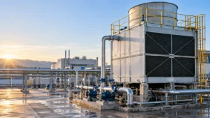
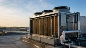
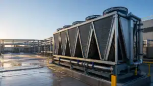
Discharge check valves stop one compressor from feeding hot gas backward through another compressor that is off. The discharge line needs supports that control vibration without loading the compressor shell. The condenser then rejects the combined heat of compression and the evaporator load. Ambient design temperature, fan control, coil cleanliness, and receiver location all affect condensing pressure.
The liquid header must deliver stable liquid to every connected circuit. A receiver that is too small cannot handle charge migration or pump-down volume. A receiver that is oversized may add cost and refrigerant inventory without solving a control problem. Ask the designer to state the charge basis and the operating level range rather than approving a receiver by nominal diameter alone.
Medium-temperature and low-temperature rack groups
Many retail and distribution sites use separate suction groups. A medium-temperature group may serve dairy, produce, beverages, or a walk-in cooler. A low-temperature group may serve frozen food, ice cream, or a freezer room. The two groups have different evaporating conditions, defrost demands, insulation needs, and compressor envelopes.
| Load group | Typical applications | Design questions | Common mistake |
|---|---|---|---|
| Medium temperature (MT) | Dairy cases, produce, beverages, meat, walk-in coolers | What product temperature and evaporating condition are required? How much door traffic occurs? | Selecting a room setpoint without checking coil TD, humidity, and product recovery |
| Low temperature (LT) | Frozen food cases, ice cream, freezer rooms | What defrost method, drain protection, and fan delay are required? | Reusing MT controls or compressor settings on an LT circuit |
| Process or specialty group | Blast chilling, holding rooms, or production equipment | Is the load steady, batch based, or highly variable? Are product probes required? | Sizing only for the average load and ignoring pull-down or simultaneous starts |
Keep the groups separate in the load calculation and in the sequence of operation. A common plant controller may supervise both groups, but each group still needs its own pressure targets, compressor staging, defrost sequence, and alarm delays. The walk-in cooler temperature guide explains why room temperature alone cannot describe an evaporator or its connected load.
Rack architectures and when to use them
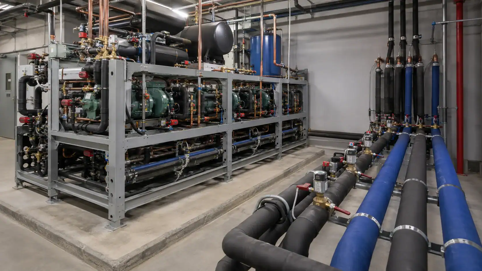
A rack is not automatically the best choice for every project. Compare the central rack with multiple condensing units, a distributed system, or a secondary-loop arrangement before the equipment list is frozen.
| Architecture | Strength | Limitation | Fit when |
|---|---|---|---|
| Parallel compressor rack | Shares capacity, condenser, controls, and service infrastructure across many loads | Common-point failures and more complex oil, controls, and commissioning work | Several circuits run from one plant room and the owner can support centralized service |
| Multiple independent condensing units | Simple isolation and familiar replacement path | More frames, condensers, electrical feeders, and separate controls | Loads are far apart or the site needs strong circuit independence |
| Distributed or close-coupled system | Shorter piping and potentially lower field installation scope | More equipment in occupied areas and less centralized maintenance | The site has limited plant-room space or short, repeatable case runs |
| Secondary-loop system | Limits refrigerant distribution in occupied areas and can centralize primary equipment | Adds pumps, heat exchangers, fluid controls, and pumping energy | The project prioritizes refrigerant containment or long case runs |
The US EPA retail food refrigeration resource gives useful system context, but it does not select a rack for a particular store. Use the site’s load profile, refrigerant plan, piping route, service model, and local code review to make that decision.
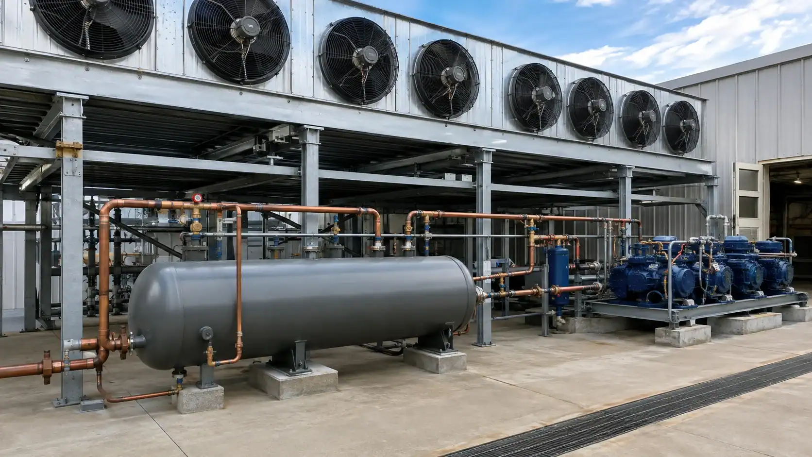
Compressor selection and oil management
Start with a block load calculation for each suction group. State design room conditions, product load, transmission load, infiltration, lighting, fan heat, defrost recovery, ambient condition, and the expected diversity between circuits. Then translate the load into compressor capacity at the actual suction and condensing conditions. A catalog horsepower value is not a load calculation.
Check the complete operating envelope. The compressor must tolerate the planned suction pressure, discharge pressure, return-gas temperature, oil temperature, motor voltage, and cycling pattern. If a compressor can only unload to a certain step, include that step in the minimum-load review. A variable-speed compressor may reduce cycling, but its drive, oil return, and minimum speed still need validation.
Oil management becomes more important as the rack grows. The separator removes oil from discharge gas, the reservoir stores it, and a controlled return path sends oil back to the crankcases. Sight glasses, differential switches, level controls, and check valves provide evidence that the system is returning oil instead of allowing one compressor to run dry while another carries excess oil.
The refrigeration compressor selection guide covers operating-envelope and quotation inputs that should be agreed with the rack designer. For a custom condenser or evaporator coil that will connect to the rack, send the refrigerant, duty, face dimensions, circuiting, pressure, and connection drawing so the coil can be reviewed with the rack rather than in isolation.
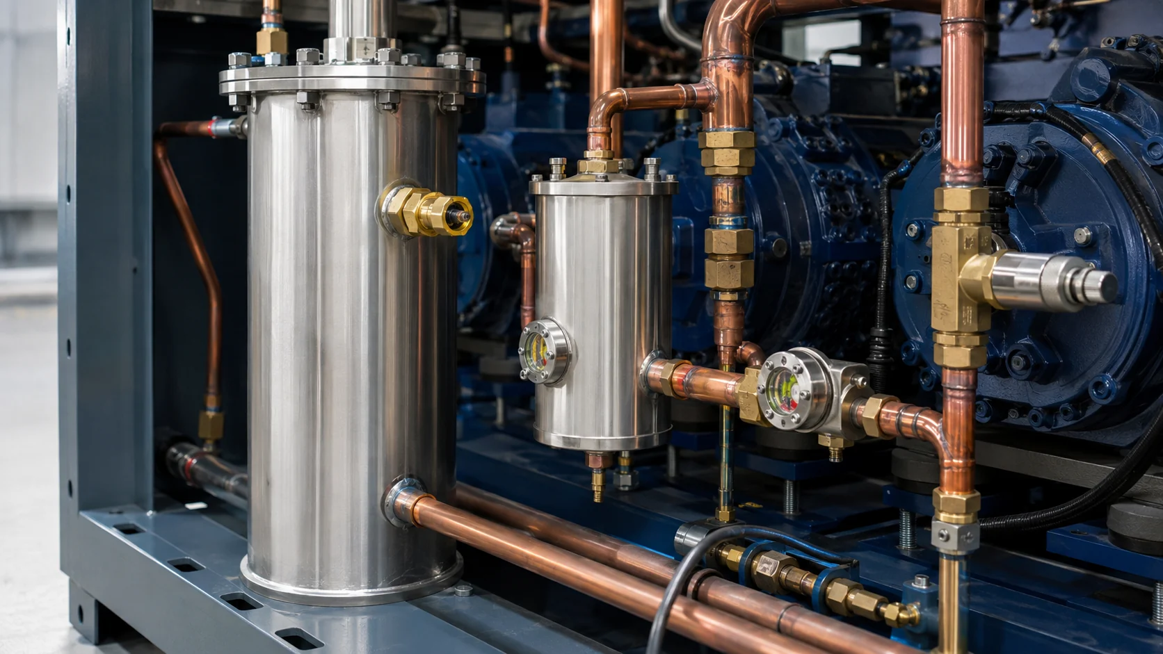
Refrigerant and CO2 rack considerations
The refrigerant choice affects pressure class, oil, valves, relief devices, controls, leak testing, and service training. A rack designed for a common HFC or HFO blend cannot be treated as a CO2 rack by changing the nameplate. Confirm the pressure ratings and the control inputs for every pressure-bearing component.
CO2 transcritical racks add high-side pressure control, gas cooler outlet temperature, receiver pressure management, and high-pressure expansion logic. The EPA advanced refrigeration technologies page describes why advanced systems use different heat-rejection and control arrangements. It is background information, not a substitute for a signed pressure design and component schedule.
For an ammonia or cascade project, include the refrigerant-side boundary, relief strategy, oil compatibility, material compatibility, and separation between circuits. Record the refrigerant and safety classification in the RFQ. Avoid using a generic “refrigeration rack” label when the design requires a specific pressure class or code review.
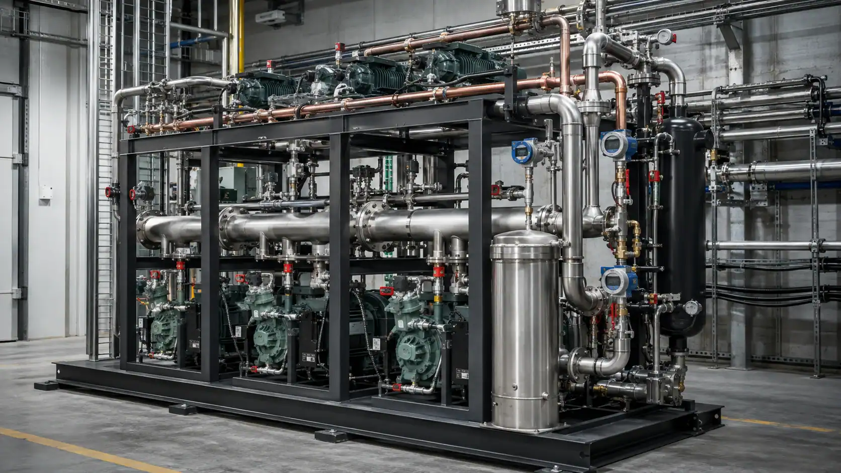
Controls, sensors, and rack safety interlocks
The rack controller should coordinate compressors, condenser fans, liquid solenoids, defrost, oil level, pressure limits, alarms, and communication. Define the sequence in plain language before selecting a controller. The refrigeration controller guide gives a practical checklist for sensors, outputs, defrost, alarms, and parameter backups.
At minimum, document these inputs and actions:
- Suction pressure or temperature for each suction group, with a defined control target and alarm limit.
- Discharge pressure and temperature, with a safe shutdown if the condenser cannot reject heat.
- Oil level or oil differential, with a timed response that protects the compressor without causing nuisance trips.
- Receiver level or liquid pressure where the chosen system needs it.
- Compressor status, overload, phase protection, and run feedback.
- Condenser fan status, ambient condition, and minimum fan speed.
- Door, leak, emergency-stop, and communication-failure inputs where the site requires them.
The control panel should include a wiring diagram, I/O list, alarm matrix, parameter backup, firmware or revision record, and a defined safe state for a failed sensor. Do not rely on a touchscreen display as proof of protection. A controller can show a pressure value while a wrong transducer range makes the value meaningless.
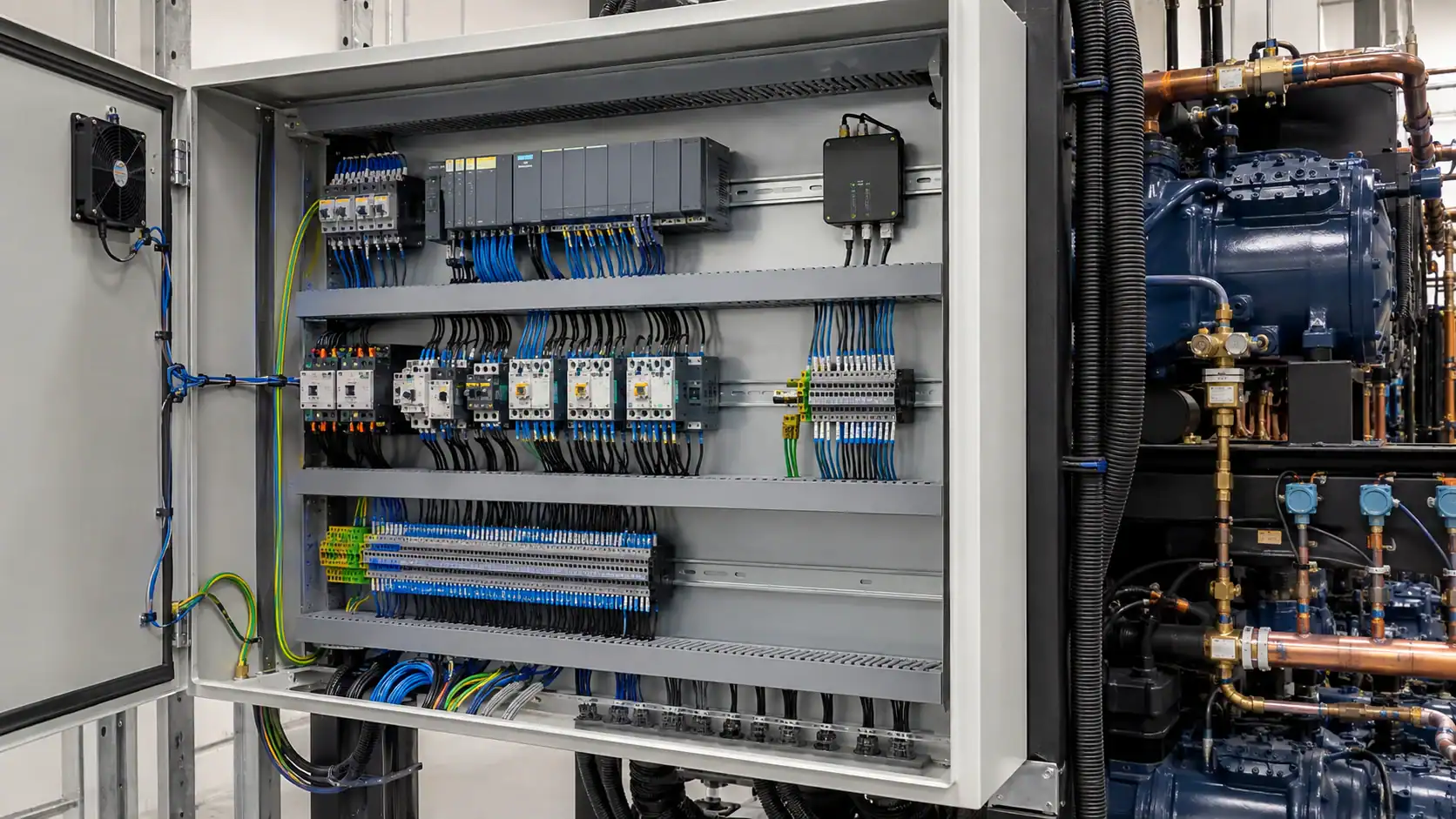
Rack sizing and RFQ information
An RFQ should give every bidder the same operating assumptions. This reduces the chance that one supplier quotes a peak-only rack while another includes diversity, defrost recovery, or a future expansion allowance.
| RFQ field | Information to provide | Why the rack designer needs it |
|---|---|---|
| Connected circuits | Case, walk-in, freezer, process, and future circuit count | Sets suction groups, branch capacity, and control points |
| Load basis | Peak and diversified load, pull-down load, defrost recovery, and design margin | Prevents an oversized minimum step or an undersized peak |
| Operating conditions | Evaporating temperature, condensing temperature or ambient, return-gas temperature | Establishes compressor capacity and operating envelope |
| Refrigerant and oil | Refrigerant, pressure class, oil type, and regulatory constraints | Selects compressors, valves, piping, relief devices, and test method |
| Condenser | Air or water cooled, design ambient, fan control, material, and fouling access | Sets heat rejection and head-pressure control |
| Site constraints | Plant-room dimensions, service clearance, electrical service, noise, and lifting route | Determines frame size, access panels, and installation sequence |
| Controls | Sensors, setpoints, staging, alarms, communication, and remote monitoring | Defines the panel hardware and commissioning tests |
| Documentation | P&ID, wiring diagram, I/O list, sequence, test records, and spares | Makes approval, service, and future replacement repeatable |
For an OEM cabinet or coil package, attach the latest drawing revision, connection orientation, tubing sizes, circuiting, material, coating, pressure test requirement, packing method, and target delivery date. If a value is unknown, mark it for confirmation. Guessing a suction condition or a connection size creates more rework than leaving one field open.
Installation and commissioning checks
Rack commissioning starts before power is applied. Compare the delivered frame with the approved drawing. Verify compressor model and rotation, pipe supports, vibration isolators, valve direction, relief discharge routing, insulation, electrical protection, and service access. Photograph the as-built piping and record any field change against the drawing revision.
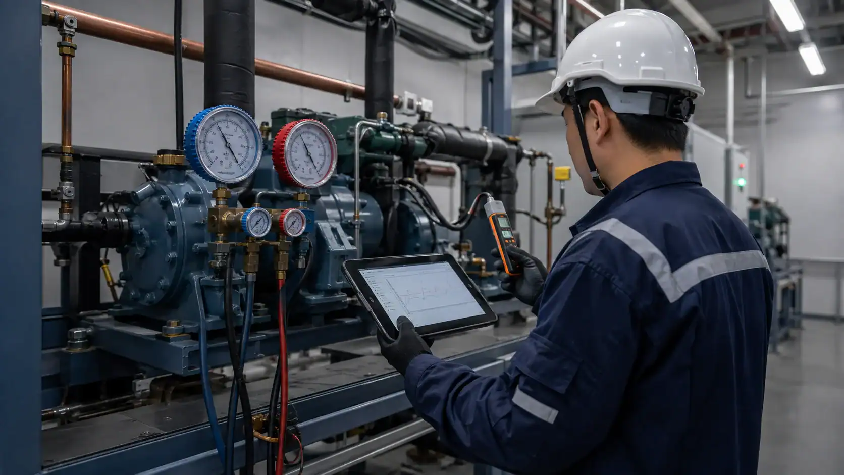
During the first run, verify each suction group separately if the design allows it. Record suction and discharge pressure, superheat, subcooling where applicable, compressor current, oil level, receiver level, condenser fan state, room temperature, and alarm state. Confirm that the lead compressor rotates, that the next step starts at the intended pressure, and that the minimum-load condition does not short cycle.
Test a simulated high-pressure trip, low-pressure trip, oil fault, sensor failure, emergency stop, power recovery, and communication loss. Each test should produce the documented alarm and safe output state. A commissioning sheet that only records “unit started” is not enough for a multi-compressor system.
Maintenance and common rack problems
A rack rewards regular measurements. Check compressor oil levels, oil differential, suction and discharge trends, condenser cleanliness, fan operation, receiver level, filter-drier pressure drop, vibration, pipe supports, and alarm history. Trend data can show a drifting condenser fan or a slow loss of capacity before the room temperature becomes an emergency.
Common symptoms have several possible causes:
- High discharge pressure: blocked condenser airflow, fouled coil, fan control failure, non-condensables, excessive ambient, or an incorrect pressure sensor range.
- Low suction pressure: low charge, a restricted liquid path, a closed valve, a starved evaporator, an incorrect expansion setting, or a load that is below the control step.
- Oil level alarms: poor separator return, a blocked return path, incorrect oil type, long piping without a return strategy, or a compressor that is running outside its envelope.
- Uneven case temperatures: an unbalanced liquid header, poor evaporator airflow, incorrect valve settings, sensor placement, or a suction group that is operating at the wrong target.
- Repeated compressor cycling: minimum capacity too large for the load, an unstable sensor, narrow differential, or an incorrect staging sequence.
Do not adjust several parameters at once. Record the original value, change one item, wait for a stable operating period, and record the result. If the cause is a coil, condenser, or piping problem, changing the controller setpoint only hides the fault.

Factory testing, documentation, and shipment
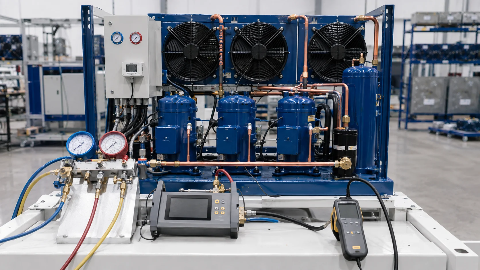
Before shipment, ask the supplier to define the inspection record. A useful factory check includes visual inspection, dimensional verification, electrical I/O checks, pressure or leak testing appropriate to the refrigerant, sensor simulation, alarm simulation, and a review of the parameter backup. The test record should identify the rack serial or project reference and the drawing revision.
Pressure testing must follow the refrigerant, component rating, local code, and approved procedure. The supplier should state the test medium, pressure, hold time, gauge accuracy, acceptance rule, and the disposition of any leak. Do not copy a test pressure from another refrigerant or pressure class.
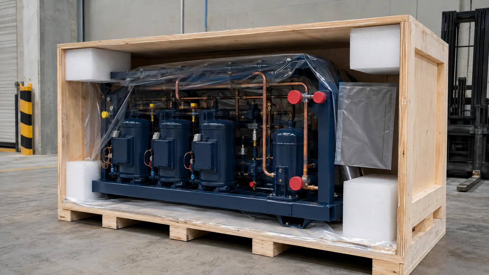
Protect the rack for the actual transport route. Cap open connections, support heavy components, protect gauges and control panels, block compressor movement, add moisture protection, and provide a packing list that matches the drawing. Photograph the crate before closing it. The OEM refrigerator and freezer solutions page can be used when a custom coil or heat-exchanger package must be coordinated with an OEM equipment build.
Frequently asked questions
What is a refrigeration rack used for?
A refrigeration rack supplies several evaporator circuits from a centralized group of parallel compressors. Supermarkets, cold-storage buildings, food distribution sites, and process facilities use racks when multiple loads can share a plant room, condenser, controls, and service infrastructure.
How many compressors does a refrigeration rack need?
There is no universal count. The designer selects the number and capacity steps from the peak and diversified load, minimum load, operating envelope, redundancy target, frame space, and future expansion plan. A small rack may use two compressors, while a large site may use several compressors across separate suction groups.
What is the difference between an MT and LT refrigeration rack?
An MT rack serves medium-temperature loads such as beverages or dairy. An LT rack serves freezer loads with lower evaporating conditions and a greater defrost burden. Each group needs its own pressure target, compressor selection, defrost sequence, insulation plan, and alarm recovery strategy.
What components are on a refrigeration rack?
A typical rack includes parallel compressors, suction and discharge headers, check valves, an oil separator and reservoir, a condenser connection, a receiver, a liquid header, service valves, pressure and temperature sensors, controls, safeties, and a frame. The exact list changes with the refrigerant, suction groups, and site requirements.
How do I size a refrigeration rack?
Calculate the peak and diversified load for each suction group at the actual evaporating and condensing conditions. Then select compressor steps that cover the peak without creating unstable minimum-load cycling. Check oil return, condenser capacity, receiver volume, piping pressure drop, controls, future load, and the required redundancy before freezing the equipment list.
What should I include in a rack RFQ?
Include the connected circuits, peak and diversified loads, temperatures, refrigerant and oil, condenser type, site dimensions, electrical service, controls, alarm requirements, documentation, pressure-test procedure, packaging, delivery date, and the latest drawings. For a custom coil connected to the rack, add the coil duty, circuiting, dimensions, materials, connections, and pressure requirement.