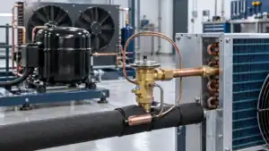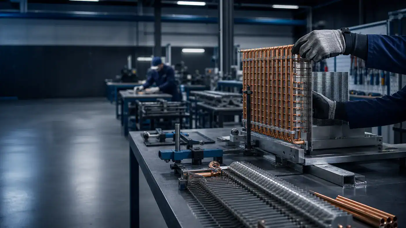
Cooling coils are HVAC heat exchangers that cool and often dehumidify air by transferring heat to chilled water, glycol, or evaporating refrigerant.
A request that says only “10-ton cooling coil” is not ready for selection. It omits the air condition, airflow, fluid or refrigerant state, pressure-drop limits, dimensions, materials, and the amount of moisture the coil must remove. Two suppliers can quote the same nominal capacity and still propose coils that behave very differently in the air handling unit.
This guide is written for engineers, AHU manufacturers, mechanical contractors, replacement-coil buyers, and procurement teams. It explains which inputs define cooling coil performance, how construction choices change fan and pump duty, and how to compare quotations without accepting hidden changes in the rating basis.
The scope is HVAC and process-air equipment. Cold-room unit coolers, display-case evaporators, and low-temperature defrost design are separate applications. Buyers working on those systems should use the coil cooler selection guide instead of treating the terms as interchangeable.
What are cooling coils in HVAC?
HVAC cooling coils are finned-tube heat exchangers installed in an air stream to reduce dry-bulb temperature and, when the surface is below the air dew point, remove water vapor.
Air passes across fins connected to tubes. The fins provide more air-side surface area, while the tubes contain chilled water, a water-glycol mixture, or refrigerant. Heat moves from the warmer air through the fin and tube wall into the colder medium. A fan supplies the air movement, and a pump or compressor maintains the medium-side condition.
That description sounds simple. Selection is not. Air is a mixture of dry air and water vapor, so a wet cooling coil must be rated as both a heat exchanger and a dehumidifying surface. The leaving dry-bulb temperature does not reveal the whole duty. The leaving humidity ratio, condensate rate, air-side pressure drop, and available fan power matter as well.
Cooling air and removing moisture
Sensible cooling lowers air temperature without changing its moisture content. Latent cooling removes water vapor by condensation. Most comfort-cooling coils perform both functions during humid weather.
The coil surface must fall below the entering-air dew point before sustained condensation begins. Once the surface is wet, some of the coil area cools air while another part removes moisture. The effective surface temperature and the way air contacts the coil determine the leaving state. A deeper coil, colder fluid, lower face velocity, or different circuit can change that balance, but each adjustment also affects resistance, freeze risk, footprint, or cost.
Psychrometric inputs keep this discussion measurable. The NIST publication on psychrometric properties of humid air explains why dry-bulb temperature, relative humidity, humidity ratio, and dew point are connected properties rather than interchangeable labels. For coil selection, entering dry-bulb plus entering wet-bulb, or another complete pair of independent properties, gives the supplier enough information to define the entering state.
An engineer may use the familiar approximation 1.08 x cfm x temperature change for sensible capacity in Btu/h near standard air conditions. It is useful for a reasonableness check, not a final wet-coil rating. Air density changes with altitude and temperature, and the formula does not include latent load. The supplier’s selection should report total and sensible capacity at the specified entering state.
Terms buyers should keep separate
A cooling coil can be an evaporator coil, but not every cooling coil contains evaporating refrigerant. A chilled-water coil receives cold water from a central chiller. A glycol coil uses a solution selected for freeze protection or process requirements. A DX coil is an evaporator because refrigerant changes state inside its tubes.
A condenser coil works on the heat-rejection side of a refrigeration cycle. It is not a substitute for an air-cooling coil. A heating coil raises air temperature. A cold-room unit cooler may include a refrigerant coil, fans, casing, drain pan, heaters, and defrost controls as one packaged product. Naming the medium and equipment function prevents an early terminology error from reaching the drawing.
| Coil description | Medium inside tubes | Main air-side result | Common equipment | Selection distinction |
|---|---|---|---|---|
| Chilled-water cooling coil | Water | Sensible and latent cooling | AHU, rooftop unit, fan-coil unit | Needs water temperatures, flow, pressure-drop limit, and freeze review |
| Glycol cooling coil | Water-glycol mixture | Sensible and latent cooling | Process AHU, outdoor unit, low-temperature loop | Needs glycol type, concentration, and design temperature |
| DX evaporator coil | Refrigerant | Sensible and latent cooling | Packaged AC, heat pump, DX AHU | Needs refrigerant, evaporating condition, superheat, distributor, and circuit data |
| Condenser coil | Refrigerant | Heats the external air while rejecting system heat | Condensing unit, heat pump outdoor section | Rated for heat rejection, not supply-air cooling |
| Refrigeration unit cooler | Refrigerant or secondary fluid | Cools a refrigerated room, often below freezing | Walk-in cooler, freezer, cold room | Requires frost, defrost, air throw, drainage, and room-load review |
Main HVAC cooling coil types
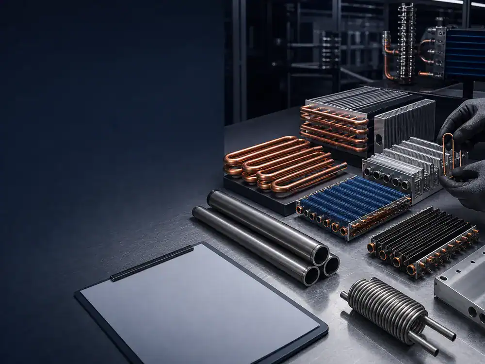
The main HVAC cooling coils are chilled-water, glycol, and direct-expansion coils, with custom replacement designs used when an existing casing or connection layout must be preserved.
The right category follows the system architecture. A central chilled-water plant leads to a water coil. A low-temperature secondary loop may require glycol. A packaged refrigerant circuit requires a DX coil matched to the refrigerant and control method. Replacing a failed coil adds another constraint: the new assembly must fit the unit and connect to existing services without giving up the required duty.
Chilled-water cooling coils
Chilled-water coils are common in central air handling systems. Water enters the coil at a specified temperature, absorbs heat, and leaves warmer. The rating depends on entering water temperature, leaving water temperature or flow, entering air state, airflow, and the required leaving air state.
The approximate water-side relationship capacity = 500 x gpm x water temperature rise gives Btu/h for water near ordinary HVAC conditions. The constant is rounded from water density and specific heat. It is not valid as written for every glycol solution or extreme temperature. Use it to catch a misplaced decimal, then rely on actual fluid properties and the manufacturer’s coil model.
Water velocity and circuiting need attention. Too little velocity can reduce internal heat transfer and make air or sediment problems harder to manage. Excessive velocity raises pressure drop and may create erosion or noise concerns. A supplier may change the number of circuits to balance heat transfer against pump duty. That is why a proposal should show both fluid flow and pressure drop rather than only entering and leaving temperatures.
Freeze protection is a system decision. A water coil exposed to outdoor winter air can freeze even when the building is occupied if valves, pumps, dampers, sensors, or controls fail. The RFQ should state the lowest entering-air condition, ventilation sequence, pump arrangement, valve fail position, and any required freeze-stat strategy. Draining a multi-row coil is not always reliable because tubes and headers can retain water.
Glycol cooling coils
Glycol lowers the fluid freezing point, but it changes more than freeze protection. Viscosity, density, and specific heat differ from water and vary with concentration and temperature. Those properties change heat transfer and pressure drop. A quote that says “glycol coil” without glycol type and concentration is incomplete.
Specify propylene glycol or ethylene glycol as applicable, the concentration by the project’s chosen basis, entering fluid temperature, leaving temperature or flow, and the lowest operating and shutdown exposure. Do not let two bidders assume different concentrations. A proposal based on 20 percent glycol cannot be compared directly with one based on 40 percent glycol.
Pump selection also belongs in the comparison. A colder, more viscous solution can produce a much higher fluid-side pressure drop than water at the same nominal flow. Increasing tube circuits may reduce that drop, but it changes velocity and heat-transfer behavior. The coil schedule should carry the selected concentration through to the final submittal so it does not disappear between design and procurement.
Direct-expansion evaporator coils
DX coils expand and evaporate refrigerant inside the tubes. Their performance depends on refrigerant, saturation temperature or pressure, superheat target, circuiting, distributor selection, orientation, airflow, and the compressor/control envelope.
Refrigerant distribution is a practical constraint. A wide coil may need multiple circuits and a distributor that feeds them evenly. Poor distribution can leave part of the coil starved while another part carries more refrigerant. The air-side symptom may be an uneven surface temperature, reduced capacity, unstable superheat, or patchy condensate.
Part-load operation deserves its own check. Variable-speed compressors and fans can move the coil far from the full-load rating point. Ask how the selected circuits behave across the expected airflow and refrigerant-flow range. A design that is stable at peak duty may need staged circuits, control changes, or another geometry to remain predictable at low load.
US refrigerant service work is subject to EPA requirements. The EPA Section 608 resources cover technician certification and refrigerant management. Coil selection does not replace the applicable installation, leak, recovery, or service rules.
Custom and replacement AHU coils
Replacement projects begin with two questions: what must remain fixed, and why did the old coil fail? The casing envelope, flange pattern, connection side, and access path may be fixed. Tube material, fin material, circuiting, rows, coating, or header design may still be open to review.
Copying every internal detail can reproduce the original limitation. If the existing coil has high air pressure drop, poor drainage, repeated freezing, corrosion at the tube sheet, or inaccessible connections, document the problem before asking for a duplicate. A replacement supplier needs the old rating point and the new duty, not only photographs and overall dimensions.
| Type | Information that controls selection | Main proposal risk | Best comparison check |
|---|---|---|---|
| Chilled water | Air state, airflow, water temperatures, flow, pressure-drop limit | Different assumed water rise or flow | Compare at identical air and water conditions |
| Glycol | Glycol chemistry, concentration, fluid temperatures, flow | Different property assumptions | Confirm the same fluid data and temperature basis |
| DX | Refrigerant, saturation condition, superheat, circuits, airflow range | Uneven distribution or different evaporating condition | Compare refrigerant condition, circuit count, and part-load range |
| Replacement | Existing rating, dimensions, connections, access, failure history | A physical fit that misses capacity or repeats a failure | Approve both performance sheet and dimensioned drawing |
Cooling coil applications by HVAC system
Cooling coils serve air handling units, rooftop equipment, fan-coil units, heat pumps, and process-air systems, but each application imposes different space, control, humidity, and maintenance constraints.
A schedule should identify the equipment and duty before listing construction. The same 100 kW load can lead to different cooling coils in a hospital AHU, a compact rooftop unit, a factory make-up air system, or a fan-coil unit. Space, filtration, operating hours, outdoor-air fraction, condensate management, and available fan or pump pressure all change the decision.
Air handling units and rooftop systems
Central AHUs often have enough face area to balance pressure drop, latent performance, and access, but the design team must still coordinate filters, upstream heating, downstream reheat, humidifiers, fans, and access sections. Coil pull space can dictate the mechanical-room layout. A large coil may need split sections or intermediate supports for transport and installation.
Rooftop equipment has tighter height and weight limits. Outdoor exposure also affects casing, headers, fasteners, freeze risk, and service access. The coil selection cannot assume the same entering air all year if the unit mixes return and outdoor air. Economizer operation, morning warm-up, unoccupied control, and ventilation demand can create rating points that are more severe than the nominal summer design.
For custom system development, Domi’s HVAC and heat pump solution path shows the broader engineering information that links coil duty to refrigerant compatibility, materials, simulation, samples, and production review.
Fan-coil units and terminal equipment
Fan-coil units force a compact tradeoff. A small face area raises face velocity. More rows may recover capacity but add resistance. The fan has limited static pressure, so a coil change can reduce actual airflow and erase the expected gain.
Noise also matters. A higher air velocity can increase regenerated noise at the coil and grille. Water velocity and valve selection can add hydronic noise. Condensate pans and drain traps must fit into a shallow casing while remaining cleanable. A replacement coil that matches only the cabinet opening may interfere with the fan scroll, filter, valve package, or access panel.
Terminal units often operate across several fan speeds. Ask for performance at the actual speed points rather than applying a simple percentage to full-load capacity. Wet-coil behavior, valve authority, and room humidity can change at low airflow.
Process air and dehumidification duties
Process applications may care more about leaving dew point, product exposure, washdown, or contamination control than comfort temperature. A coil serving food processing, pharmaceutical production, drying, or a humidity-controlled room needs a clear cleanliness and material specification.
Dehumidification can require colder surfaces and then reheat. The cooling coil must reach the required humidity ratio, not merely a target dry-bulb temperature. If the supply air is reheated after dehumidification, show the cooling and reheat duties as separate processes. Otherwise, a supplier may select a coil for the final supply temperature and miss the required dew-point reduction.
Drainage is part of the air-quality design. Specify pan material, slope, outlet position, trap allowance, access, and cleaning method. If the coil will be washed, identify the cleaning chemicals and pressure limits. “Hygienic design” needs concrete construction and access requirements before it can be quoted.
Rating conditions that define coil capacity
Cooling coil capacity is valid only at a stated air condition, airflow, fluid or refrigerant condition, and pressure-drop basis. Nominal tons do not replace those inputs.
The rating point is the contract between the load calculation and the selection of cooling coils. If it changes, the capacity changes. Procurement should protect that basis through the request, proposal comparison, submittal, and approved drawing.
Entering and leaving air conditions
Provide entering dry-bulb and wet-bulb temperatures, or another complete psychrometric pair. Then state either the required leaving condition or the total and sensible duties that the coil must meet. When humidity control matters, specify leaving humidity ratio or dew point rather than relying only on relative humidity.
Relative humidity can be misleading because it changes with dry-bulb temperature. Air at the same moisture content has a higher relative humidity after sensible cooling. A request for “55 F at 90 percent RH” describes a different moisture state from “55 F at 50 percent RH.” The coil model needs one defined state, not a casual humidity label.
The entering condition should reflect the air at the coil face. Mixed air from return and outdoor streams may differ from outdoor design air. Fan heat can matter if the fan is upstream. Heat recovery and preheat sections can change both temperature and moisture. Record where each scheduled state is measured.
Airflow, face velocity, and moisture carryover
Airflow sets the mass of air the coil must treat. Face velocity is airflow divided by active coil face area. Increasing face velocity can reduce the required face size, but it usually raises air-side pressure drop and can make condensate carryover more likely.
There is no universal face-velocity limit for every wet coil. Fin geometry, rows, casing, eliminators, drain design, air distribution, and orientation all matter. A project specification may use a maximum such as 500 feet per minute for a wet coil, but the supplier still needs to confirm carryover and pressure drop for the proposed geometry. Treat the project limit as an acceptance criterion, not a law of nature.
Air distribution deserves a review when the upstream duct turns sharply, filters load unevenly, a fan discharge is close to the coil, or the coil is split into unequal sections. A selection program assumes a defined airflow. It cannot correct a casing that sends most of the air through one corner.
Water or glycol conditions
State entering fluid temperature and either leaving temperature or flow. If both are fixed, verify that they are consistent with the required load. Include the allowable fluid-side pressure drop and available pump information when it is known.
For glycol, add chemistry, concentration, and the temperature at which properties are evaluated. The selection output should repeat those inputs. If the supplier reports only “30 percent glycol” without identifying the type or property basis, ask for clarification.
Water quality and closed-loop treatment influence service life but should not be invented by the coil supplier. State any material restrictions, treatment program, oxygen exposure, cleaning method, and applicable project standard. Copper tubes may be common, but stainless steel or another material can be required by the fluid or environment.
Refrigerant conditions for DX coils
Name the refrigerant and the evaporating or saturation condition. Include superheat, liquid condition if relevant to the selection, airflow range, circuit staging, and control method. If the refrigerant is still under project review, request separate selections rather than letting a quotation mix assumptions.
The EPA Technology Transitions Program organizes restrictions by product and system category. That structure reinforces a practical design rule: refrigerant choice must be tied to the equipment end use and regulatory schedule before connection sizes, pressure basis, and circuiting are frozen.
Part-load and off-design points matter for variable systems. Ask for the minimum stable operating condition and any required circuit staging. The supplier may need compressor-map and expansion-device data from the system designer; a coil-only selection cannot determine the entire refrigeration control envelope.
Use ratings that can be compared
AHRI 410 covers performance ratings for forced-circulation air-cooling and air-heating coils. The AHRI 410 standard page is a useful reference when the project requires a defined rating method. The scope and certification requirements should be stated explicitly. Do not write “AHRI coil” as a substitute for naming the applicable standard, conditions, and certification status.
For project-specific or process coils outside a standard rating scope, require the supplier to identify the calculation method, software revision if relevant, fluid-property source, fouling assumptions, tolerances, and exclusions. The purpose is reproducibility. Another engineer should be able to see why two outputs differ.
Construction specifications and performance tradeoffs
Tube diameter, rows, circuiting, fin geometry, materials, casing, and connections determine whether cooling coils meet capacity, pressure-drop, size, corrosion, and maintenance requirements together.
No single construction is best for every project. More surface can improve capacity, but it also adds resistance, material, depth, and cleaning effort. A useful specification for cooling coils defines the performance and interfaces first, then identifies construction limits that come from the application.
Tube diameter, rows, and circuiting
Tube diameter influences internal area, fluid velocity, pressure drop, refrigerant volume, bend geometry, and available tooling. It should not be changed casually in a replacement design. If a supplier proposes another diameter, compare performance and connections rather than rejecting it from habit.
Rows deep increase surface and contact time within a fixed face area. They can improve total capacity and dehumidification, but each row adds air resistance. Deep coils also need cleaning access and enough downstream space for drainage and air distribution. A compact eight-row selection may demand more fan power than a wider four-row selection.
Circuiting distributes the fluid or refrigerant among tube paths. More parallel circuits tend to reduce fluid pressure drop and velocity for a given total flow. Fewer circuits tend to increase velocity and pressure drop. Heat transfer can improve with velocity up to the point where pumping cost, erosion, noise, or practical limits become unacceptable.
For DX coils, circuiting also affects refrigerant distribution and pressure drop. The distributor, tube orientation, face split, and circuit length must work together. A bid comparison should show circuit count or at least confirm that circuiting is included in the manufacturer selection and will be frozen at submittal.
Fin spacing, material, and coatings
Fins per inch, often abbreviated FPI, changes the available air-side surface within a given depth. Closer spacing can raise dry, clean capacity, but it also raises pressure drop and collects dirt more quickly. In a wet coil, condensate bridging and drainage behavior matter. In a dusty process, wider spacing may preserve performance longer between cleanings.
Aluminum fins and copper tubes are common, but exposure should drive the final combination. Coastal salt, acidic or alkaline process air, cleaning chemicals, sulfur compounds, and continuous wetting can require different materials or a compatible coating. State the exposure and cleaning method. Do not ask for “maximum corrosion resistance” without a test or material basis.
Coatings add another thermal and manufacturing interface. Ask the supplier to identify the coating type, application coverage, relevant test basis, repair method, and effect on performance. Edge coverage, tube-sheet contact, cut surfaces, and field damage can matter as much as the product name.
Air-side and fluid-side pressure drop
Pressure drop is not a secondary line on the schedule. Air-side drop adds to fan static pressure. Fluid-side drop adds to pump head. Both continue for the life of the coil and can cost more than a small difference in purchase price.
Compare clean and, when the project requires it, expected fouled conditions. Filters protect coils but do not eliminate buildup. Wet surfaces may collect particles differently from dry surfaces. A system with limited fan reserve can lose airflow as filters and coils load, reducing both sensible and latent performance.
On the fluid side, check the pressure drop at the specified temperature and glycol concentration. Pump curves, control valves, balancing devices, and piping losses determine whether the design flow will occur. A coil selection that assumes flow the pump cannot deliver is not a capacity solution.
Casing, headers, connections, and drainage
Casing dimensions must match the equipment, but construction details affect leakage, strength, corrosion, and installation. Specify flange style, mounting orientation, intermediate supports, lifting needs, access side, and whether the coil ships as one section or several.
Header and connection geometry often causes field rework. Define connection size and type, centerlines from fixed datums, projection beyond casing, vent and drain requirements, and the reference side used for left-hand or right-hand connections. A marked drawing is stronger than the phrase “same as existing.”
Wet cooling coils need drainage. Coordinate fin orientation, casing drain paths, downstream pan, pan slope, outlet, trap depth, and available service clearance. Negative-pressure and positive-pressure sections have different trap behavior. The coil supplier may provide the coil casing while the AHU manufacturer provides the pan and trap, so the interface needs an owner.
The ASHRAE ventilation standards resource identifies the broader ventilation and indoor-air-quality framework used by many projects. A coil specification should coordinate with the applicable project standard, especially where drain pans, access, filtration, and cleanability affect the air path.
| Design change | Likely benefit | Likely penalty or risk | What to verify |
|---|---|---|---|
| Larger face area | Lower face velocity and often lower air pressure drop | Larger casing, higher material use, more space | Equipment envelope, transport, and access |
| More rows | More surface in a fixed face area | Higher air pressure drop and harder cleaning | Fan reserve and service method |
| Closer fin spacing | More air-side surface | More fouling and wet-coil bridging risk | Air cleanliness, filter plan, and cleaning interval |
| More parallel fluid circuits | Lower fluid pressure drop | Lower tube velocity and possible distribution concerns | Velocity, venting, and heat-transfer result |
| Fewer fluid circuits | Higher internal velocity | Higher pump head, noise, or erosion risk | Pressure-drop limit and material guidance |
| Colder water or refrigerant | More temperature difference and latent potential | Freeze risk, plant/compressor penalty, condensation burden | System energy and control sequence |
| Protective coating | Better compatibility for a named exposure | Added cost, possible thermal penalty, repair needs | Test basis, coverage, and maintenance |
How to select and compare cooling coil proposals
Select cooling coils by issuing one complete rating basis, then comparing capacity, leaving-air condition, pressure drops, geometry, materials, documentation, and deviations at that same basis.
The comparison of cooling coils should begin before quotations arrive. A bid form with fixed input fields prevents each supplier from filling gaps differently. It also gives procurement a way to separate a real design improvement from a changed assumption.
Step 1: Lock one rating basis
Create a single project schedule. Include equipment type, total and sensible load, entering and leaving air states, airflow, altitude if relevant, fluid or refrigerant data, allowable air and medium pressure drops, dimensions, materials, and operating range.
Identify the governing point. Peak sensible load may control capacity, while a humid part-load condition controls leaving dew point. An outdoor-air unit may need summer, winter freeze, and minimum-flow checks. List required secondary points rather than asking every bidder to guess them.
Do not accept catalog tonnage as the comparison basis. One nominal ton equals 12,000 Btu/h, or about 3.517 kW, but that conversion says nothing about entering air, latent share, chilled-water temperature, or pressure drop. The scheduled rating point must carry those details.
Step 2: Compare capacity and leaving-air state
Check total capacity, sensible capacity, and the actual leaving dry-bulb and humidity condition. If the selection reports a sensible heat ratio, confirm that it follows from the stated total and sensible values.
A higher total capacity is not automatically better. It may come from a colder fluid, more airflow, higher pressure drop, or a different entering state. Oversizing can also affect valve control and part-load operation. The proposal should meet the required point with a clear margin policy rather than the largest possible number.
Step 3: Compare fan and pump penalties
Record air-side pressure drop at the selected airflow. Then check whether it is dry or wet and whether accessories are included. A wet-coil value may differ from a dry-coil value. The AHU fan selection must use the same basis.
For water and glycol coils, compare flow and fluid-side pressure drop. A coil that saves face area but adds pump head shifts cost into the hydronic system. For DX coils, review refrigerant pressure drop, distributor, circuit arrangement, and the compressor/control assumptions that affect system performance.
EnergyPlus is a whole-building energy simulation program maintained with support from the US Department of Energy. The EnergyPlus program page illustrates why coil, fan, pump, controls, and building loads belong in one system model when lifecycle energy is being evaluated. A procurement comparison does not need a full simulation every time, but it should not ignore the equipment that pays for coil resistance.
Step 4: Review dimensions and service access
Confirm face width and height, depth, casing flanges, connection side, connection centerlines, header projection, vent and drain points, weight, lifting, and shipping splits. Then check the installed access path.
Filters must be removable. Coil faces must be reachable for inspection and cleaning. Drain pans and outlets need access. Valves and sensors cannot block the coil pull path. If the assembly is split, the field joint and support method need documentation.
Step 5: Record deviations and exclusions
Every proposal should have a deviation schedule. If a supplier changes airflow, glycol concentration, water temperature, casing material, fin spacing, pressure-drop limit, or test scope, the change belongs in that schedule.
Exclusions matter too. Controls, valves, drain pans, distributors, sensors, insulation, coatings, test records, freight, export packing, and field assembly may or may not be included. Procurement should not discover those boundaries after the technical selection is approved.
Replacement cooling coil measurement and RFQ data
A replacement cooling coil RFQ needs the original duty, current operating condition, dimensioned interfaces, connection geometry, materials, failure history, and required documentation.
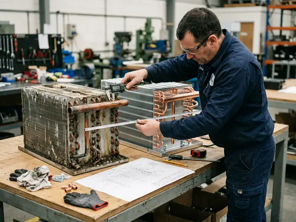
Measure replacement cooling coils before removal when possible. Photograph the coil in the unit with a ruler or known reference in the frame. Mark airflow direction and the viewing side used for connection orientation. Record which dimensions are fixed and which can change.
Dimensions and connection geometry
Capture overall casing width, height, and depth; finned width and height; rows deep; tube diameter; approximate fin spacing; flange dimensions; mounting holes; header size; connection size and type; connection centerlines; vent and drain positions; and projection beyond the casing.
Use fixed datums. Measuring one connection from the left casing edge and another from the fin pack creates ambiguity. A simple dimensioned sketch with one origin is better than a large photo set with no orientation.
Confirm the removal path. A coil may fit the opening but still be impossible to install because a wall, pipe rack, cable tray, or permanent equipment blocks the pull distance. Large sections may need removable frames, split construction, or field assembly.
Operating data and failure history
Provide the original schedule and recent operating measurements when available. Useful readings include airflow or fan speed, entering and leaving air temperature and humidity, fluid temperatures, flow, valve position, fluid pressure drop, refrigerant pressures, superheat, and condensate behavior.
Describe why replacement is needed. A tube leak near the tube sheet suggests a different review from widespread fin corrosion, freeze rupture, dirty-face pressure drop, or a casing that no longer seals. Do not ask for an identical copy until the failure mechanism has been considered.
Testing, documents, quantity, and packing
State the required design pressure basis, test method, test record, material documentation, drawing format, submittal timing, inspection points, and applicable code. Exact requirements vary by system and jurisdiction, so unknown fields should be marked for engineering confirmation rather than filled with assumptions.
Add quantity, prototype or sample needs, repeat-order expectations, destination, packing constraints, lifting limits, and requested delivery window. If an export crate or corrosion protection is required, state the transport and storage conditions.
For drawing-based or replacement work, the custom coil fabrication process provides a more appropriate commercial path than sending only a keyword and nominal capacity.
An effective RFQ package includes:
- Equipment and application description
- Total and sensible load, if both are controlled
- Entering and required leaving air state
- Airflow and allowable air-side pressure drop
- Water, glycol, or refrigerant conditions
- Allowable fluid-side pressure drop
- Altitude and operating range where relevant
- Dimensional drawing and connection datums
- Tube, fin, casing, header, and coating requirements
- Drainage, access, cleaning, and hygiene requirements
- Design pressure, test, document, and code requirements
- Quantity, schedule, destination, and packing needs
- Photographs, original schedule, and failure history for replacement work
Cooling coil priorities for 2026 and beyond
Cooling coil projects in 2026 increasingly need refrigerant-specific design, lower fan and pump penalties, verifiable rating data, corrosion planning, and access for inspection and cleaning.
These priorities do not make basic geometry obsolete. They make tradeoffs more visible. A smaller coil can save space while raising air resistance. A colder fluid can reduce surface while increasing plant energy and freeze exposure. A tighter fin pack can improve clean rating performance while shortening the cleaning interval.
Refrigerant and fluid decisions will stay application-specific
DX coil pressure basis, connection sizes, circuiting, refrigerant volume, distributor, and controls all depend on the selected refrigerant and equipment category. Projects should settle the regulatory and safety path before approving manufacturing drawings.
Hydronic systems face their own fluid decisions. Glycol concentration should follow the actual exposure and system plan. Excess concentration can add pumping and heat-transfer penalties. Insufficient concentration can leave the system vulnerable. The coil quotation should repeat the approved fluid, concentration, and temperature basis.
Lower resistance needs a system boundary
Fan and pump energy are recurring costs. Ask whether a larger face area, different row count, or revised circuiting can reduce resistance without losing latent performance or exceeding the equipment envelope.
The answer should be based on more than one number. Compare coil cost, casing impact, fan or pump duty, control range, access, and expected maintenance. A low-pressure-drop coil that cannot reach the required leaving dew point is not efficient. A compact coil that requires a larger fan may not be economical.
Corrosion, hygiene, and maintainability affect lifecycle value
Material selection should name the exposure. Cleaning access should match the actual contaminant. Drainage should work at the unit pressure and operating orientation. Sensors and access doors should allow the owner to observe entering and leaving conditions, pressure drop, leakage, and condensate.
Keep the input sheet, selection output, approved drawing, material list, coating specification, test record, and deviations together. That file becomes the baseline for commissioning, troubleshooting, and eventual replacement.
Cooling coils FAQ
These answers address the HVAC cooling coil questions that most often affect equipment selection, humidity control, replacement, and quotation review.
What is a cooling coil in HVAC?
A cooling coil is an HVAC heat exchanger that transfers heat from air into chilled water, glycol, or evaporating refrigerant. If its surface is below the air dew point, it also condenses moisture and dehumidifies the air. Bottom line: specify both the heat-transfer medium and the entering air state.
What are the main types of cooling coils?
The main types are chilled-water, glycol, and DX refrigerant cooling coils. Chilled-water and glycol coils use pumped liquid. DX coils evaporate refrigerant inside the tubes. Replacement coils can use any of these types but add strict dimensional and connection constraints. Bottom line: select the category from the system architecture, not the coil’s appearance.
Do cooling coils remove humidity?
Yes, when the coil surface is below the entering air dew point. Water vapor condenses on the fins and drains into a pan. The amount removed depends on the entering moisture state, surface condition, airflow, geometry, and leaving target. Bottom line: provide dry-bulb and wet-bulb or dew-point data when latent performance matters.
What is the difference between a cooling coil and an evaporator coil?
An evaporator coil is a cooling coil that evaporates refrigerant, while a chilled-water cooling coil contains liquid water rather than boiling refrigerant. Both can cool and dehumidify air, but their circuits, controls, pressure basis, and selection inputs differ. Bottom line: use “DX evaporator” or “chilled-water coil” in the RFQ.
How do rows and fins per inch affect cooling coil performance?
More rows and closer fin spacing can add heat-transfer surface, but they also tend to increase air resistance and cleaning difficulty. Wet operation, dirt, available fan pressure, coil depth, and service method determine whether the added surface is useful. Bottom line: compare capacity and air-side pressure drop together.
What face velocity should be checked for a wet cooling coil?
Use the project limit and require the supplier to verify pressure drop and condensate carryover for the proposed geometry. Values near 500 feet per minute are common specification checkpoints, but there is no universal limit for every fin, row, casing, and airflow distribution. Bottom line: treat face velocity as a design input that still needs manufacturer confirmation.
What information is needed to size a cooling coil?
Sizing needs airflow, entering and leaving air conditions, total and sensible load, fluid or refrigerant data, pressure-drop limits, dimensions, materials, and operating range. Glycol projects need type and concentration. DX projects need refrigerant and evaporating conditions. Bottom line: send a complete rating schedule rather than nominal tons alone.
How should buyers compare replacement cooling coil quotations?
Compare quotations at identical air, fluid, refrigerant, dimensional, material, testing, and documentation conditions. Record every changed assumption as a deviation. Confirm the drawing, connection datums, access path, pressure drops, and included scope before comparing price. Bottom line: approve the performance sheet and mechanical drawing as one package.

Preparing an HVAC cooling coil request for review
A usable cooling coil request combines one defined rating point with mechanical interfaces, materials, operating limits, testing needs, and a clear list of unknowns for engineering review.
Start with the equipment and system type. Add airflow, entering and required leaving air conditions, load, water/glycol/refrigerant data, allowable pressure drops, dimensions, connections, materials, drainage, access, operating range, test requirements, quantity, and destination. Attach the original schedule and a dimensioned drawing for replacement work.
Do not hide missing data behind a broad request for “high efficiency.” Mark unknown values and ask which measurements are required. That approach gives the supplier a defensible basis for thermal selection and gives procurement a clean way to compare offers.
For a project-specific review, request an HVAC coil review and include the operating conditions with the drawing. Domi can then identify missing selection inputs before a quotation is finalized.