
Thermal conductivity describes how readily a material carries heat by conduction. Its usual symbol is k, and its SI unit is W/(m·K). A higher value means more heat passes through the same material geometry under the same temperature difference. It does not, by itself, tell you the heat output or cooling capacity of a finished coil.
When comparing copper tube, aluminum fins or alternative coil constructions, look beyond the material data sheet. A higher conductivity may make little difference if airflow or a poor joint limits the assembly. This guide starts with the property and its units, then follows the heat path to the decisions an OEM buyer needs to check.
Jump to the part you need:
What does thermal conductivity measure?
Conductivity connects a temperature gradient within a material to the heat flowing through it. Think of a tube wall separating a warm fluid from a cooler surface: the metal has a conductivity, the wall has dimensions, and the assembly has operating conditions. Each describes a different part of the problem.
Conduction can occur in solids, liquids and gases. In a coil, heat also crosses moving-fluid boundary layers, so a metal property cannot describe the entire exchange. OpenStax explains the conduction relationship using material conductivity, geometry and the temperature difference across the conducting layer.
High conductivity is useful when you want heat to spread through a tube wall or along a fin. Low conductivity is useful when you want insulation to resist that movement. Neither is a universal measure of product quality. Choose according to the intended heat path and the other requirements the part must meet.
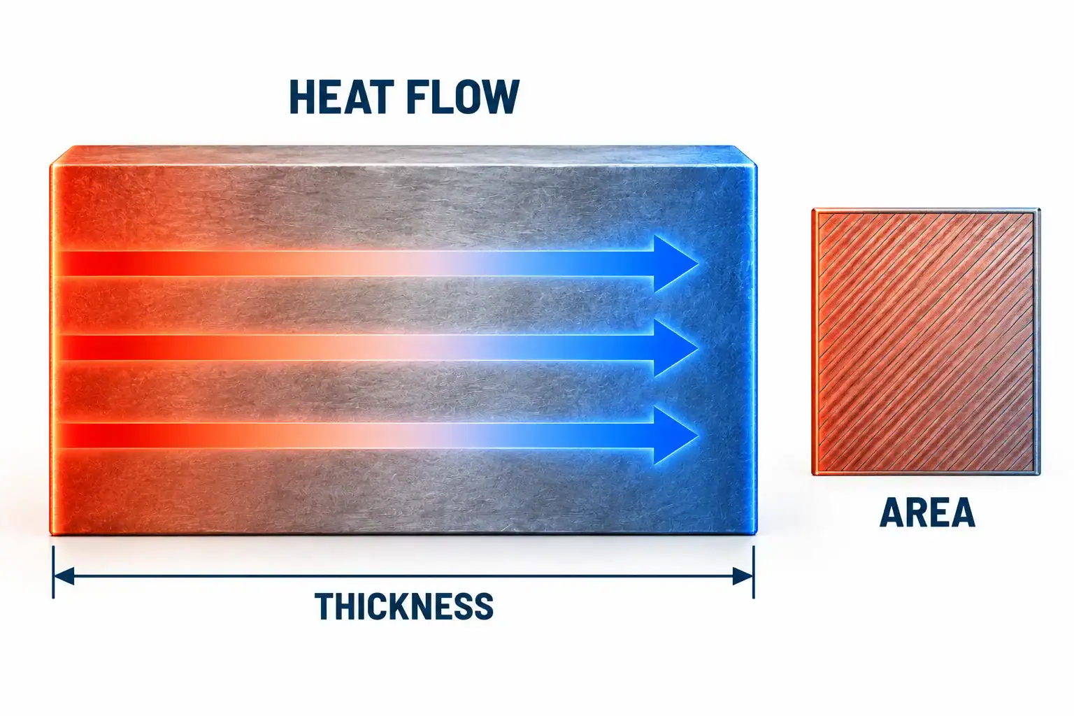
Concept illustration of conduction. The technical visuals in this guide explain heat paths and specification questions; they are not photographs of Domi facilities or laboratory test records.
Which thermal conductivity units should a drawing use?
Use W/(m·K) and keep the denominator grouped. The watt describes heat-transfer rate, the meter accounts for the material path and area relationship, and the kelvin describes a temperature difference. Conductivity is different from a heat-transfer coefficient in W/(m²·K).
For a temperature difference, one kelvin has the same size as one degree Celsius. A conductivity quoted in W/(m·°C) therefore has the same numerical value as one in W/(m·K). This does not make absolute temperatures in kelvin and Celsius interchangeable. The NIST SI guide provides the relevant unit definitions and temperature-interval convention.
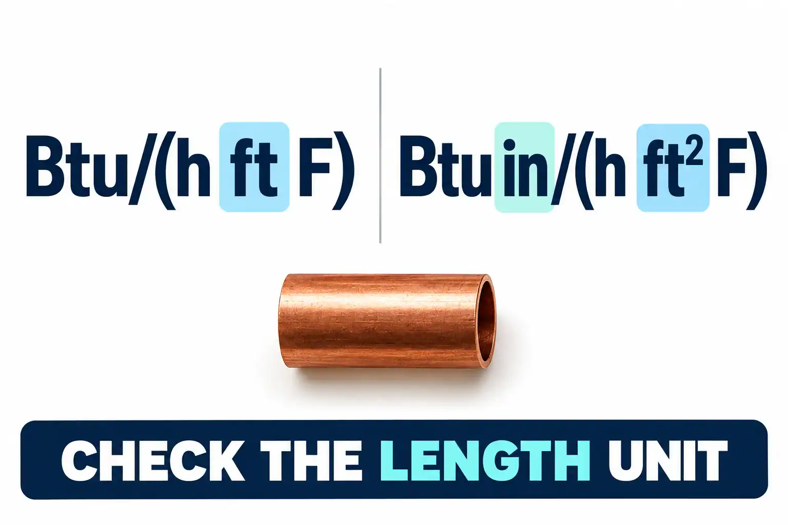
Imperial data need a closer look. Using the International Table Btu convention:
- 1 Btu/(h·ft·°F) is approximately 1.7307 W/(m·K).
- 1 Btu·in/(h·ft²·°F) is approximately 0.14423 W/(m·K).
Those factors differ by 12. The inch-based expression includes thickness in the numerator; it is not the same notation as the foot-based expression. Before importing a supplier number, copy the complete unit, identify the Btu convention if precision matters, and convert once in a controlled calculation. A bare number such as “200” is not an adequate property specification.
How do you calculate conduction through a wall?
For steady, one-dimensional heat flow through a flat layer with constant conductivity, the magnitude is:
Q̇ = k × A × ΔT / t
Here, Q̇ is heat rate in W, A is area perpendicular to flow in m², ΔT is the temperature difference across the layer in K, and t is thickness in m. Heat flux, Q̇/A, has units W/m². The negative sign in the directional form of Fourier’s law indicates that heat travels toward lower temperature; the expression above uses positive magnitudes.
As a simple calculation, assume k = 200 W/(m·K), A = 0.01 m², t = 0.002 m and a temperature difference of 1 K across the solid. The result is 1,000 W. This is a hypothetical layer calculation, not a coil capacity rating: it assumes the stated temperatures already exist at the two solid faces.
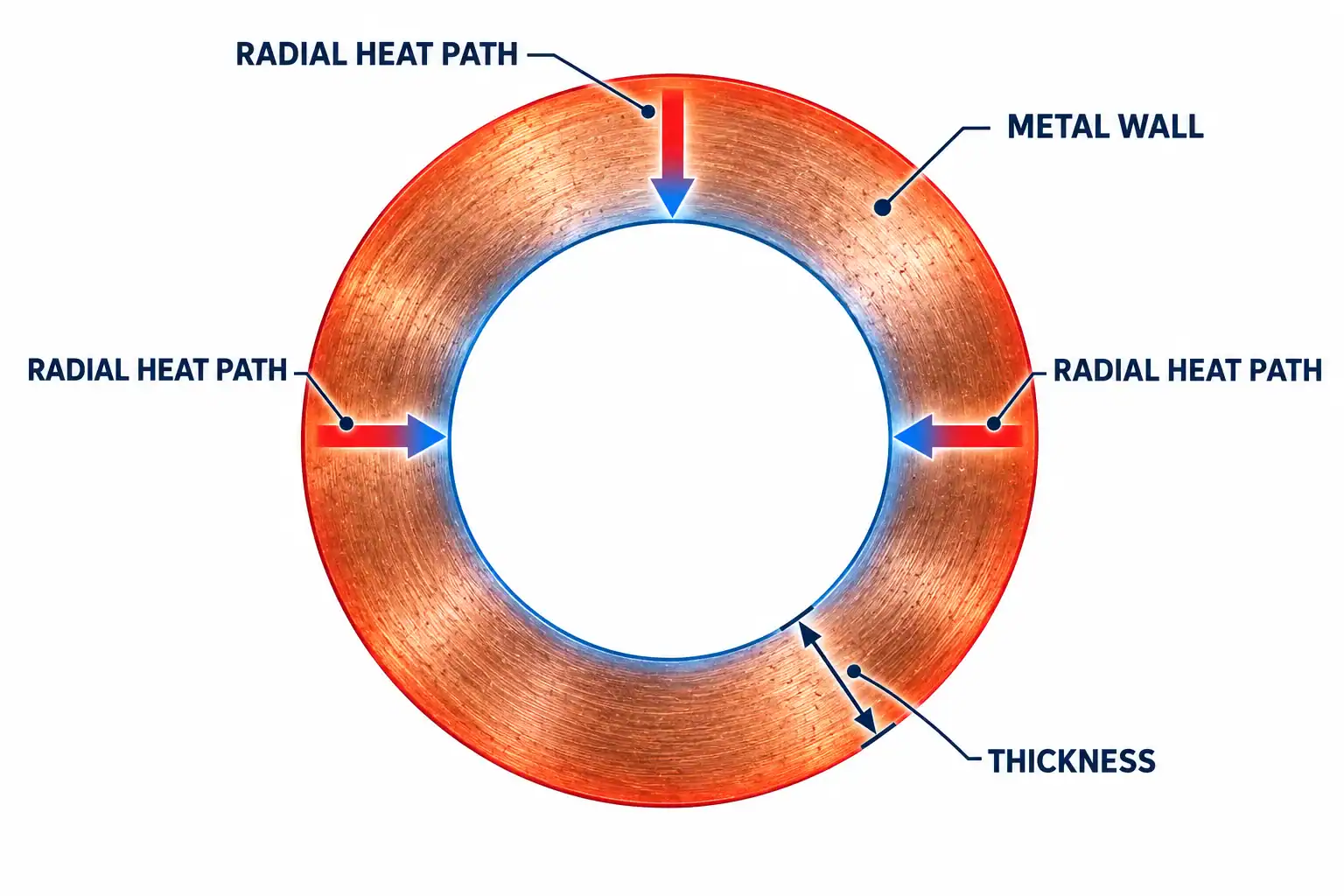
A round tube requires its cylindrical geometry when wall resistance is important. For a uniform cylindrical wall, resistance is ln(rₒ/rᵢ)/(2πkL), using outer radius, inner radius and tube length. A flat-wall approximation needs justification for the geometry. A fin also has temperature variation along its length. Neither should be reduced to “conductivity multiplied by total coil area.”
Thermal conductivity vs heat-transfer coefficient
k is a material property; h describes a surface exchanging heat with a fluid; U describes a combined heat-transfer path on a stated area basis. Comparing their numerical values is meaningless because their definitions and units differ.
Thermal conductance, G, is another quantity. For the flat layer above, G = kA/t in W/K. Its resistance is 1/G in K/W. The same metal can therefore form two parts with very different conductances simply because their thicknesses or areas differ.
Check the notation in each document. Some manufacturers use λ for conductivity and k for an overall coefficient. Alfa Laval’s calculation method uses that convention and separates material, surface-film and fouling terms. A symbol without its definition and units is easy to misread.
For the broader assembly calculation, see our guide to heat-transfer coefficient, U and UA. Keep that rating question separate from the material-property question addressed here.

Copper vs aluminum: compare grades, not just metal names
Copper generally offers higher conductivity than common aluminum coil alloys, but “copper” is not one specification. Alloy chemistry and condition matter. A value for high-conductivity electrical copper should not automatically become the design value for deoxidized refrigeration tube.
The following are published supplier references. They are useful for understanding scale and differences, not for certifying a Domi material batch or guaranteeing a finished coil’s performance.
Material reference
Published conductivity, W/(m·K)
Published basis
How to use the value
Material reference: Cu-ETP / C11000, KEMPER
Published conductivity, W/(m·K): 385
Published basis: Approximate value, soft state, ambient temperature
How to use the value: Reference for this named grade and condition; ambient is not a precise test temperature
Material reference: Phosphorus-deoxidized C12200, Austral Wright
Published conductivity, W/(m·K): 293 to 364
Published basis: Data sheet range at 20°C
How to use the value: Retain the range until the actual supplied material and design basis are agreed
Material reference: Aluminum 3003, Austral Wright
Published conductivity, W/(m·K): 193
Published basis: Physical-property value at 25°C
How to use the value: Reference for 3003; do not apply it to every aluminum alloy or temper
The sources are the KEMPER Cu-ETP data, Austral Wright C12200 sheet and Austral Wright 3003 sheet. Their qualifications are part of the information. The C12200 reference, for example, supplies a range rather than a single guaranteed conductivity.
For procurement, choose an alloy and form that can meet the pressure, corrosion, joining and fabrication requirements. Then check its conductivity on the agreed basis. Choosing only the largest property number can leave the more important manufacturing or service constraint unanswered.

Why reference temperature and condition matter
A room-temperature value is a reference point, not a complete temperature-dependent property model. If the design spans a substantial temperature range, ask whether the selected conductivity is evaluated at a representative wall temperature or taken from a suitable property curve. Do not assign the air inlet temperature to the metal automatically.
Record the alloy designation, product form and supplied condition alongside the number. If a source gives an approximate soft-state value, keep that qualification. If a table lists several tempers elsewhere but does not assign its conductivity to a particular one, avoid inventing that connection.
Three labels help during review: published reference, measured specimen result and design input. They may have different values for valid reasons. Ask the engineer to document how the first two support the third. A conservative design input should have a stated basis, rather than appearing as an unexplained adjustment in a spreadsheet.

Does doubling conductivity double coil capacity?
No. It halves the conduction resistance of an unchanged wall under the constant-k assumption. The change in total heat transfer depends on how much of the original resistance belonged to that wall.
Consider an illustrative flat-wall model, using equal area on both sides, no fouling or contact resistance, a 0.5 mm wall, and assumed film coefficients h₁ = 1,000 and h₂ = 50 W/(m²·K). Hold those inputs and the bulk-fluid temperature difference fixed. Compare assumed conductivities of 200 and 400 W/(m·K); these are model inputs, not measurements of the grades above.
On this equal-area basis:
1/U = 1/h₁ + t/k + 1/h₂
Model quantity
k = 200 W/(m·K)
k = 400 W/(m·K)
Model quantity: First film resistance, m²·K/W
k = 200 W/(m·K): 0.001
k = 400 W/(m·K): 0.001
Model quantity: Wall resistance, m²·K/W
k = 200 W/(m·K): 0.00000250
k = 400 W/(m·K): 0.00000125
Model quantity: Second film resistance, m²·K/W
k = 200 W/(m·K): 0.020
k = 400 W/(m·K): 0.020
Model quantity: Overall U, W/(m²·K), rounded
k = 200 W/(m·K): 47.613
k = 400 W/(m·K): 47.616
Doubling k changes U by only about 0.006% in this deliberately film-dominated example. At a heat flux of 1,000 W/m², the assumed second film accounts for 20 K of temperature drop, while the two walls account for 0.0025 K and 0.00125 K respectively.
This is not a prediction for a real finned coil. Such a coil has different inner and outer areas, fin efficiency, contacts, circuiting and operating states. The example establishes a review question: what share of the total resistance will the proposed material change actually remove? A supplier claiming a capacity gain should answer that question with a model or test under matched conditions.

Where conductivity matters in tubes and fins
In a tube, conductivity contributes to heat moving across the wall. Wall thickness also serves pressure and manufacturing requirements, so reducing it to improve conduction is not an independent thermal decision. Check the required pressure design and fabrication constraints before changing the drawing.
In a fin, heat must spread away from the tube contact into a larger surface. Conductivity, fin thickness, distance from the tube and the air-side exchange all affect the temperature distribution. Higher conductivity can be useful here even when the through-wall term is already small. Our guide to how radiator fins work covers that surface-area function in more detail.
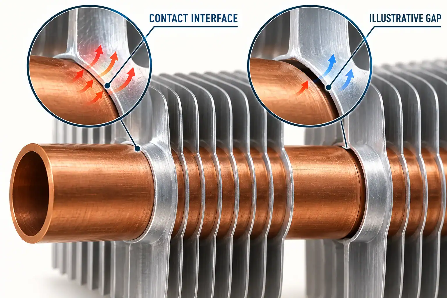
A good bulk-metal value also cannot remove resistance at a poor fin-to-tube interface. Include contact gaps, coatings and deposits in the review. Their importance depends on the construction and service environment; a concept illustration cannot quantify them.
When comparing proposals, ask where each design expects the largest temperature drop. If the answer is the air-side exchange, investigate the airflow and surface design before paying for a different tube alloy. If the answer is fin spreading or an interface, inspect those features directly.
What evidence should support a conductivity value?
Ask first whether the value comes from a handbook, a supplier data sheet or a measurement of the supplied product. Each can be useful, but they support different claims. A general data-sheet value should not be presented as a batch test result.
For a measurement, request the method, specimen identification, temperature conditions, direction of heat flow where relevant, and the reported uncertainty or repeatability information. The specimen dimensions and preparation should be clear enough to judge whether the result represents the part being purchased. A test-method name alone does not explain all of that.
Keep property evidence and assembly evidence in separate files. A conductivity report describes a material or specimen under its test conditions. A coil rating or prototype test describes an assembly under specified fluid, air and installation conditions. Neither substitutes for the other. If the buying decision depends on a claimed capacity improvement, request the matched assembly comparison as well as the material data.

A material specification that can survive supplier review
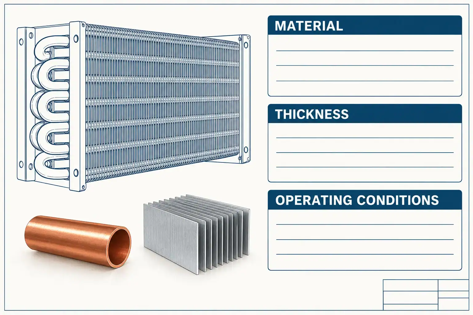
An RFQ that says only “high-conductivity copper coil” leaves too many decisions open. Send a drawing and a short requirement sheet that identifies:
- Material: alloy designation, applicable product specification and permitted alternatives.
- Condition: required temper or delivered condition, including any forming or joining constraints.
- Geometry: tube dimensions, wall thickness, fin dimensions and the interfaces relevant to heat flow.
- Property basis: conductivity source, unit, reference temperature, and whether the number is typical, measured or a design input.
- Duty: fluids, flow conditions, temperatures, required heat load and allowable pressure drop.
- Environment: condensate, contaminants, cleaning exposure and the corrosion question to resolve.
- Construction: joining method, fin contact and coating requirements that affect the complete heat path.
- Acceptance evidence: material documentation and any agreed prototype or assembly-performance comparison.
If a supplier proposes a substitution, ask for the changed drawing revision and property basis together. Then review thermal performance, joining, pressure and corrosion implications before accepting it. Keeping the old drawing with a new material name in an email is difficult to audit later.
For mixed-metal assemblies, use a separate galvanic-corrosion review. Conductivity does not establish compatibility with the fluids or environment, and a higher k cannot compensate for a material that fails in service.
Frequently asked questions
What is the thermal conductivity of copper?
Use the exact grade and temperature. The references above give approximately 385 W/(m·K) for soft Cu-ETP at ambient temperature and a 293 to 364 W/(m·K) range for C12200 at 20°C. These supplier references are not a universal copper value or a guaranteed batch result.
Is copper more thermally conductive than aluminum?
For the named references above, the copper values exceed the aluminum 3003 value. That comparison concerns the material property. A copper assembly does not automatically outperform an aluminum assembly with different dimensions, interfaces, airflow or operating conditions.
What is the difference between conduction and conductivity?
Conduction is the heat-transfer process. Conductivity is a material property used to calculate that process. Thickness, area and temperature difference are also needed to calculate a heat rate for a simple conducting layer.
What is the thermal conductivity of stainless steel?
There is no single value covering all stainless steels and temperatures. Specify the grade, condition and operating-temperature range, then obtain an appropriate property source. A generic stainless-steel label is insufficient for a design comparison with a particular copper or aluminum alloy.
Is W/(m·K) the same as W/(m²·K)?
No. The first is a conductivity unit. The second is commonly used for a surface or overall heat-transfer coefficient. They describe different quantities and cannot be compared by their numerical values alone.
Is thermal conductivity the same as thermal diffusivity?
No. Thermal diffusivity, α = k/(ρcₚ), also includes density and specific heat capacity. It helps describe how temperature changes propagate through a material over time. Conductivity alone does not describe its transient response.
Can a coating affect a highly conductive metal part?
Yes. A coating adds another layer with its own thickness and properties, and may affect surface behavior. Evaluate its role in the actual heat path alongside its protective purpose. Do not assign the underlying metal’s conductivity to the complete coated construction.
Can I calculate coil capacity from conductivity alone?
No. Conductivity supplies one material input. An assembly rating also needs geometry, fluid-side behavior, fin and contact effects, operating conditions and an appropriate calculation or test basis. Ask for a capacity at your specified conditions rather than inferring it from k.
Review the material and heat path before choosing a coil
Use conductivity to check a material claim, then assess the complete construction. Review the drawing with the alloy, thickness, interfaces and operating duty together. If performance evidence is still missing, define the comparison conditions before discussing a claimed gain.
Domi’s engineering capabilities and custom coil fabrication pages describe the relevant design and manufacturing services. Send your current drawing, proposed material alternative, operating temperatures and required heat duty. Ask the team to confirm feasibility, the assumptions requiring review and the evidence needed for the next decision. Material availability, tolerances and validation scope should be confirmed for the particular project.