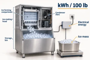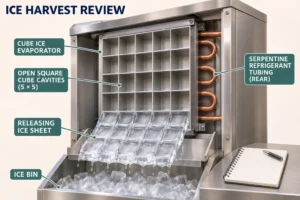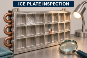

An ice machine harvest cycle releases formed ice from the evaporator and prepares the machine for another freeze cycle. Faster release can shorten the production cycle, but an OEM must also check delivered ice mass, energy use, recovery time and reliability. Optimize the complete sequence: heat delivery, plate response, ice geometry, harvest assistance and release detection. A shorter timer alone does not demonstrate a better evaporator.
This guide addresses batch-type commercial cube machines. ENERGY STAR distinguishes batch machines from continuous flake and nugget equipment: the first alternates freezing and harvesting, while the second operates continuously. Do not apply a batch harvest-time target to an auger machine simply because both produce ice.
OEM refrigeration engineers first need to identify which part of the sequence limits acceptable ice delivery. The framework below separates that question from routine fault repair and from a supplier’s isolated coil rating. The drawings are explanatory concepts. They do not document Domi testing, prescribe approved piping or demonstrate measured gains.

Jump to cycle calculation · heat delivery · prototype testing · energy
Define the harvest boundary before comparing times
Two teams can report different harvest times from the same machine if their start and end events differ. One may start at the controller command; another may start when the plate begins to warm. One may stop at the first moving cube; another may wait until the last retained ice clears the forming surface.
Define the events in the test plan. Record the command to begin harvest, the first visible release, final release, the controller’s end signal and the return to the next accepted freeze state. Events may overlap in a particular design. Count each interval once when building the total cycle time.
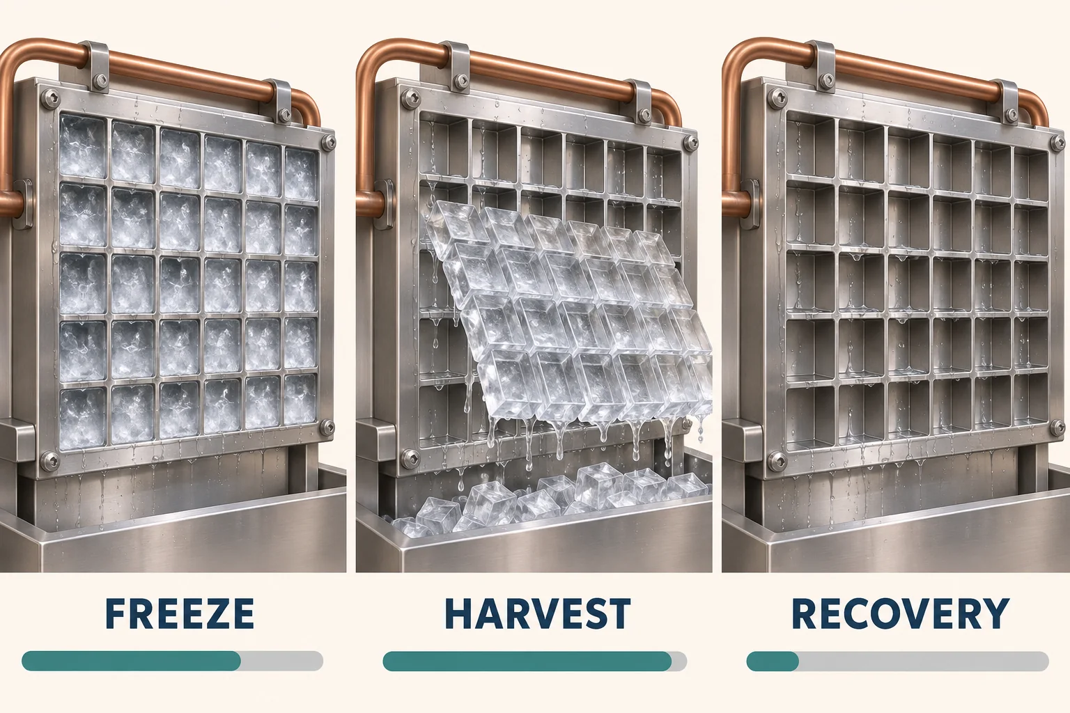
Keep normal production separate from startup, cleaning recovery, bin-full restart and protective retries. These conditions can use different sequences. The Scotsman C-series service manual, for example, documents model-specific limits and restart behavior. Its values are instructions for the covered equipment, not design targets for every OEM platform.
Use the same event definitions when asking two evaporator suppliers for sample data. Without that agreement, a shorter reported interval may only reflect a different stopwatch boundary.
Calculate the production opportunity from the whole cycle
For a simplified continuously operating batch machine, potential daily delivered ice can be estimated as:
Daily ice = accepted ice mass per cycle × 1,440 / total cycle time in minutes.
Total cycle time includes the non-overlapping freeze, harvest and other necessary transition intervals. This is a planning calculation, not a certified capacity rating. Bin-full periods, downtime, operating conditions and rejected ice can change actual output.
Consider a hypothetical machine delivering 4.0 kg per cycle. Assume 18 minutes for freeze, 3 minutes for harvest and 1 minute for a separate recovery interval. The total is 22 minutes, giving approximately 261.8 kg/day under uninterrupted operation.
| Hypothetical case | Result |
|---|---|
| Baseline: 4.0 kg in 22 min | 261.8 kg/day |
| Same mass, harvest reduced by 1 min | 274.3 kg/day |
| One minute saved, but delivered mass falls to 3.8 kg | 260.6 kg/day |
In this example, a one-minute saving raises potential output by about 4.8% only if the other assumptions remain unchanged. Losing 0.2 kg per cycle removes that benefit. A design change therefore needs a delivered-mass measurement, not just a record that ice started moving earlier.
Use this calculation to decide whether an optimization program is worth testing. Do not use it as evidence that a proposed plate will achieve the assumed time saving.
Map first release and final release separately
The first falling section may look encouraging while a corner remains attached. Record where release starts, where it finishes and whether those locations repeat. Use the release map to see whether the delay affects the whole plate or stays at one feature.
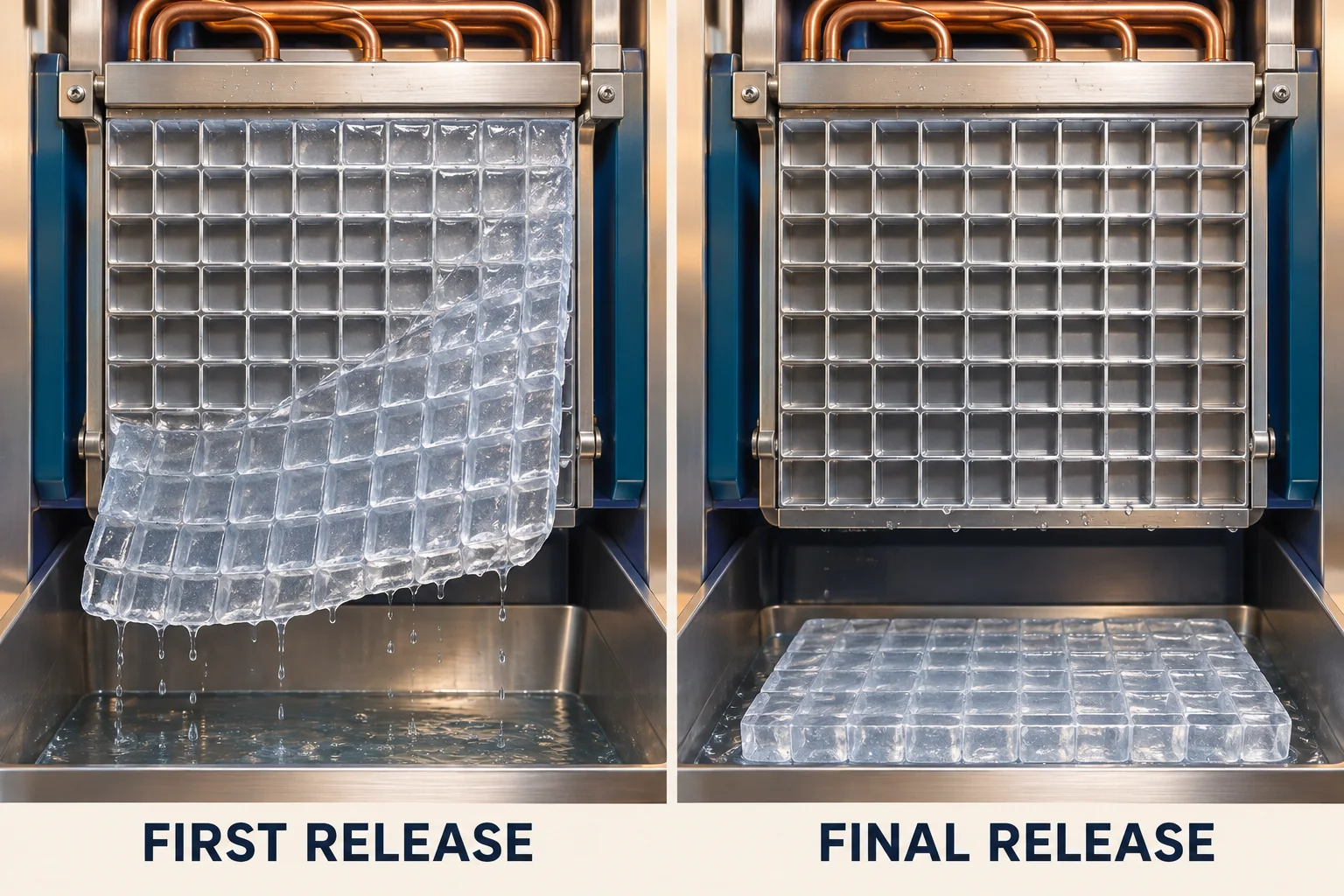
Use synchronized video and event logging when practical. Mark the plate orientation and cavity positions on a drawing so that “upper right” means the same location to the laboratory, supplier and field team. Record partially retained ice, broken sheets and ice that interferes with the next cycle.
Separate observation from explanation. A late corner could justify reviewing local heat delivery, cavity geometry, water distribution or mechanical restraint. The video alone does not establish which mechanism caused it. Choose the next measurement from the pattern, then test that explanation under controlled conditions.
This map also gives procurement a more useful requirement than “fast harvest.” A supplier can review repeatable late-release locations against a controlled drawing and a stated acceptance rule.
Review heat delivery before changing the plate
In hot-gas harvest designs, heat must reach the evaporator through the intended refrigerant path. A slow response can involve the valve, piping, operating refrigerant state or the available supply condition, as well as the evaporator itself. Other machine architectures use different release methods.

The Scotsman manual describes a covered design in which the hot-gas valve and harvest-assist mechanism operate during harvest. That provides an example of coordinated functions, not permission to copy its circuit, voltage checks or timing into an unrelated machine. Electrical and refrigerant work belongs to qualified personnel following the applicable equipment procedure.
For an OEM comparison, document the refrigerant, compressor basis, harvest valve command, inlet and outlet response and relevant system conditions. Use consistent sensor placement and sampling. Ask whether an apparent plate delay remains after the supply and control conditions are matched.
The ice machine condenser selection guide covers the separate heat-rejection boundary. Include that boundary in the machine test when ambient or condensing conditions change the available operating state.
Balance thermal mass against freeze performance
A simplified sensible-heat estimate is Q = m × c × ΔT. It explains why the mass of a component and its required temperature change affect the energy needed to warm it. Real harvest also involves ice-interface behavior, heat losses, nonuniform temperatures and the machine’s release mechanism, so this equation is not a complete harvest model.

Reducing plate mass is a candidate engineering change, not an automatic improvement. A thinner or different construction may alter stiffness, joining, temperature distribution and freeze behavior. Compare those effects with the benefit the project is trying to obtain.
Ask the supplier to identify the mass and construction being changed, the surfaces that carry heat, and the mechanical interfaces that must remain fixed. If a proposed drawing changes several features at once, record them separately. Otherwise, a successful prototype may leave the team unable to identify which change helped and which created a new limitation.
Retain the same freeze acceptance criteria. A plate that warms quickly but takes longer to form acceptable ice may increase the full cycle time.
Trace the path from tubing to the last cavity
The heat source does not contact every part of the ice surface directly. Tube routing, attachment, backing construction and grid joints create the physical path between the refrigerant and the forming surface. Review that path against the locations identified in the release map.

Give the supplier a controlled drawing with tube location, attachment details, joint specification and inspection access. A finished assembly should represent the intended production process. A specially prepared demonstration sample may hide the variation that matters in a production program.
Proposed checks can include dimensional inspection, agreed joint or contact inspection and a repeatable temperature-response comparison. Define what each method can establish. A refrigerant containment test does not prove uniform thermal contact; a smooth front face does not prove the rear attachment is consistent.
The general ice machine evaporator guide explains the broader drawing and quotation inputs. For a harvest project, add the actual release pattern and the design change being evaluated.
Keep cavity geometry and the freeze endpoint together
Cavity shape, ice bridges and the amount of ice formed at harvest entry should be reviewed as one design condition. Comparing two plates with different ice mass or a different freeze endpoint can conceal the reason their harvest times differ.
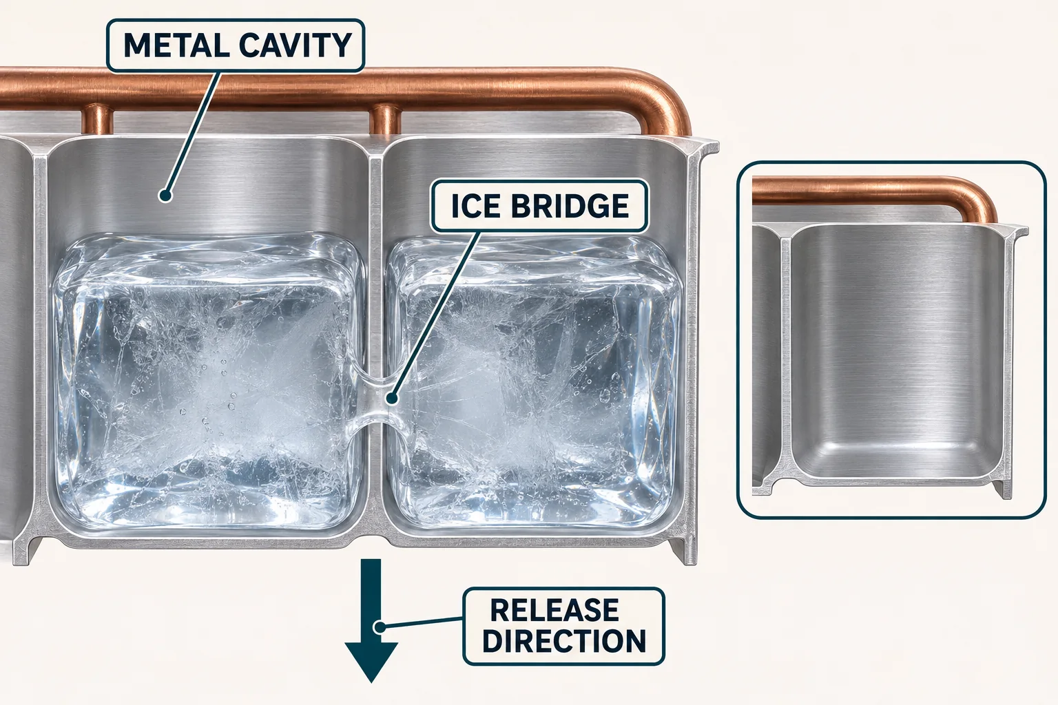
Define the intended ice form and acceptable bridge condition before the test. Record the complete delivered batch and any retained or broken ice. Where geometry changes, check the resulting product against the buyer’s requirements rather than accepting an easier release that produces the wrong ice.
The proposed review should include dimensional tolerances and production variation. A single well-performing cavity does not validate the full plate or a production lot. Avoid specifying an undocumented surface treatment solely because a sample appears slippery.
If the investigation concerns damaged plating or deposits, use the separate evaporator corrosion and scale guide. Optimization testing needs a defined surface condition; it should not quietly compare a damaged baseline with a clean candidate and call the difference a geometry improvement.
Specify the harvest-assist interface
A mechanical assist, where the machine uses one, creates another interface between the evaporator, ice and controls. Its contact point, travel, clearance and sequence belong in the assembly review. Do not treat it as a generic force that can be increased until the ice falls.
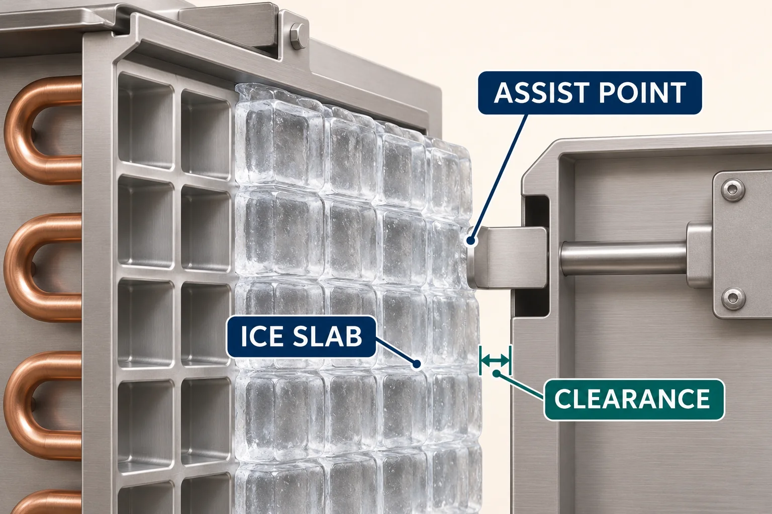
Document which parts are responsible for alignment and which party owns the mechanism. Check the interface across permitted tolerances and operating states. Record whether ice release precedes, accompanies or follows the intended assist action.
If a candidate plate needs a different assist location or sequence, disclose that dependency in the quotation. A component that performs only with an unapproved mechanism change is not a direct replacement. Keep proposed changes subject to the OEM’s machine-level review.
For a design without mechanical assistance, keep it out of the acceptance plan. The purpose is to validate the actual architecture, not add every feature found in another manufacturer’s manual.
Preserve the water state entering harvest
Water distribution and the freeze endpoint determine what the harvest sequence receives. Record inlet-water conditions, distribution pattern, ice mass and the relevant control state. Compare samples after the machine reaches the same defined operating condition.

Scotsman’s PS-2-2025 bulletin, for its named UC models, discusses scale, surface defects, surrounding seals and controls in freeze-up investigations. It supports checking more than the metal surface when ice fails to release; it does not establish universal causes or settings.
For an optimization trial, write down the surface preparation and cleaning state. Document any changes to water flow, purge or fill behavior. If those change during the trial, the team must decide whether it is still testing the evaporator alone or evaluating a broader system revision.
Check the release signal as well as the release
The controller may recognize the event through a curtain, switch, sensor or another model-specific method. Physical release and the signal that ends harvest are different observations. A delay between them can make the controller’s recorded harvest time look worse than the plate’s actual release behavior.

Log the physical event and the control transition on the same time basis. Record missed events, retries and cases where a sheet falls but does not trigger the intended detection. Also check the opposite failure: a signal that ends the phase while ice remains on the surface.
Do not bypass protective limits to improve a recorded time. A proposed sensor location or control revision needs its own acceptance criteria and responsible reviewer. Preserve the hardware and software revision with each test record so that a plate result cannot be separated from the controls that produced it.
Compare prototypes at a common test condition
Begin with a repeatable baseline. Define ambient and inlet-water conditions, refrigerant/system configuration, ice form, surface preparation, machine controls and the event boundaries. Use the same measurement methods for baseline and candidate parts.
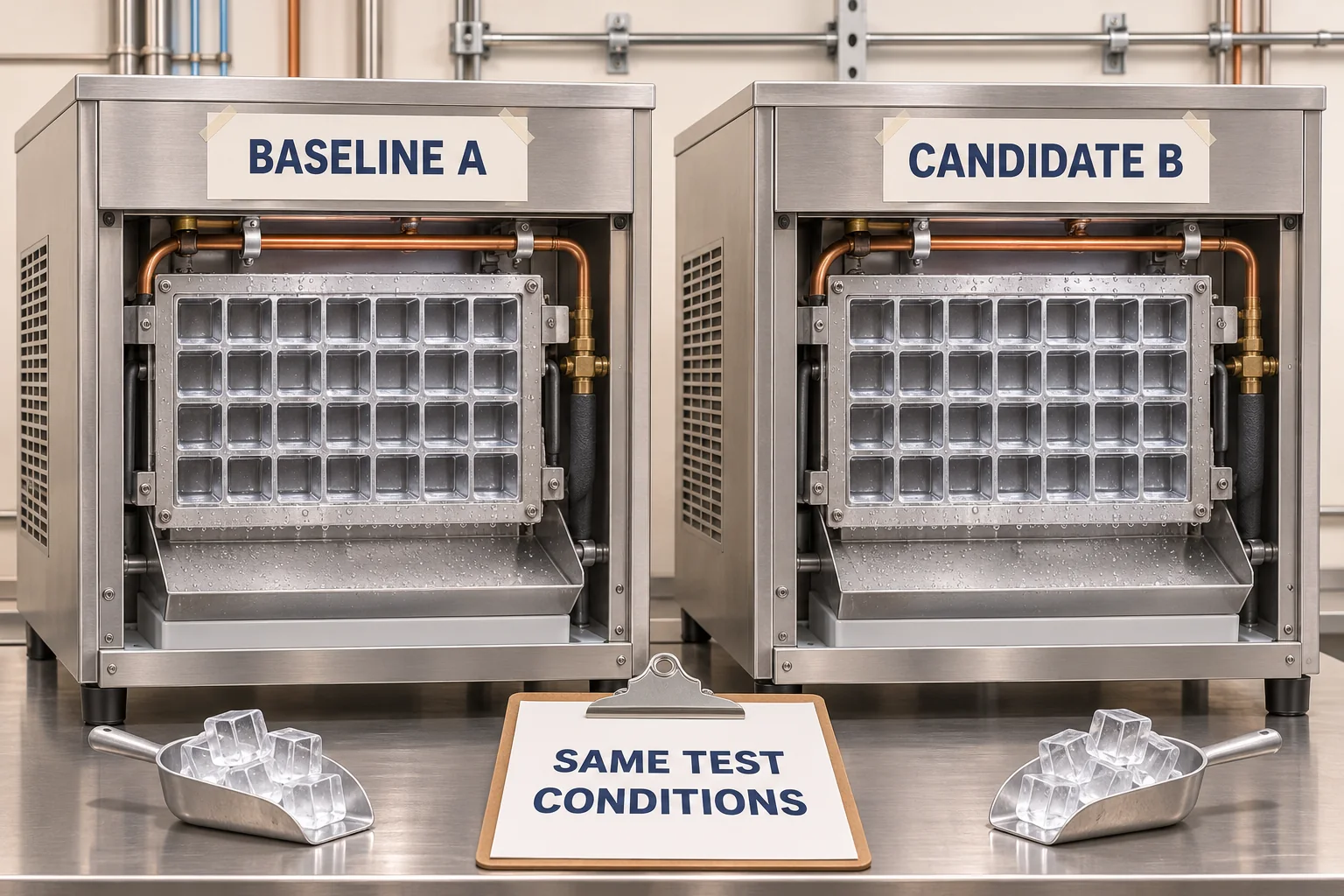
As a proposed OEM protocol, test repeated stabilized cycles, record the spread in results and retain abnormal cycles. Include relevant operating extremes and restart conditions in the broader validation program. Select repetitions and limits according to the project’s risk; this article does not prescribe a universal test count.
A first-stage trial can isolate one change. A later integration trial can evaluate the final combination of plate, piping, assistance and controls. Keep those results distinct. The candidate’s fastest cycle should not be compared with the baseline’s slowest cycle.
Before release, agree on acceptable delivered mass, incomplete release, cycle variability, recovery and inspection results. A shorter mean harvest time can still be unsuitable if retained ice or protective retries become more frequent.
Measure energy per delivered ice mass
Use a consistent whole-machine measurement window. For a simplified comparison:
Specific energy = electrical energy in the test window / accepted ice delivered in that window.
State whether the boundary includes pumps, fans, controls and other auxiliaries, and account for remote equipment where applicable. Record water use separately. A timer cannot measure either energy or water efficiency.

In a hypothetical example, 0.40 kWh for a 4.0 kg accepted batch equals 0.100 kWh/kg. A candidate using 0.39 kWh but delivering only 3.8 kg equals approximately 0.103 kWh/kg. The electrical energy per batch fell, while energy per delivered mass rose. These numbers explain the calculation; they are not Domi results or commercial-machine benchmarks.
ENERGY STAR’s commercial ice-maker program concerns eligible complete equipment and specified performance criteria. This article’s arithmetic is not a substitute for the applicable rating method and does not establish certification or eligibility for a custom component.
Frequently asked questions
What happens during an ice machine harvest cycle?
Formed ice releases from the evaporator and the machine transitions toward its next operating state. The heating, water and mechanical sequence depends on the architecture. Follow the documentation for the actual model.
What is a good harvest time?
There is no universal value for every plate and machine. Use the model’s operating limits and compare repeated results under the stated conditions. Define whether the time ends at first release, final release or the controller signal.
Does a faster harvest always increase daily production?
Only if the full-cycle result improves. Changes in ice mass, freeze duration, recovery or rejected batches can remove the benefit of a shorter harvest interval. Compare accepted delivered mass over the same operating window.
Is a thinner evaporator always better?
No. Lower mass may change warming demand, but the construction must also meet thermal-contact, stiffness, joining, freeze and durability requirements. Validate the complete proposed revision.
Can more hot gas solve a slow release?
Do not assume so. First establish the permitted system state and the cause of delay. The refrigerant circuit, compressor and controls need an engineering review; changing supply without that review can move the machine outside its intended operation.
Why does one corner release last?
A repeatable location suggests where to investigate, but does not identify the cause by itself. Compare heat response, geometry, water distribution, surface condition and restraint at that location before choosing a change.
How do I compare two evaporator proposals?
Give both suppliers the same drawing boundaries, machine configuration, operating conditions and event definitions. Request assumptions and deviations with the results. Compare delivered mass, variability and validation scope alongside price and timing.
What should an OEM send for a harvest review?
Send the drawing revision, refrigerant and machine basis, cycle-event log, release video or map, ice mass, operating conditions and acceptance limits. Identify whether assistance or control changes are permitted.
Send the cycle evidence with the evaporator drawing
Give the supplier a defined design question. “Faster ice release” alone leaves the test conditions and acceptance decision open. Identify the late event, its location, the current cycle budget and the change being considered. Keep unknowns visible.

Domi’s custom coil fabrication page provides the drawing-based project route. Ask the team to confirm whether the evaporator construction, joining process and requested validation fit its scope. Attach the baseline evidence before requesting a sample quotation. Component supply, complete-machine performance and certification are separate responsibilities to agree in the project.