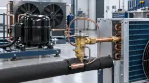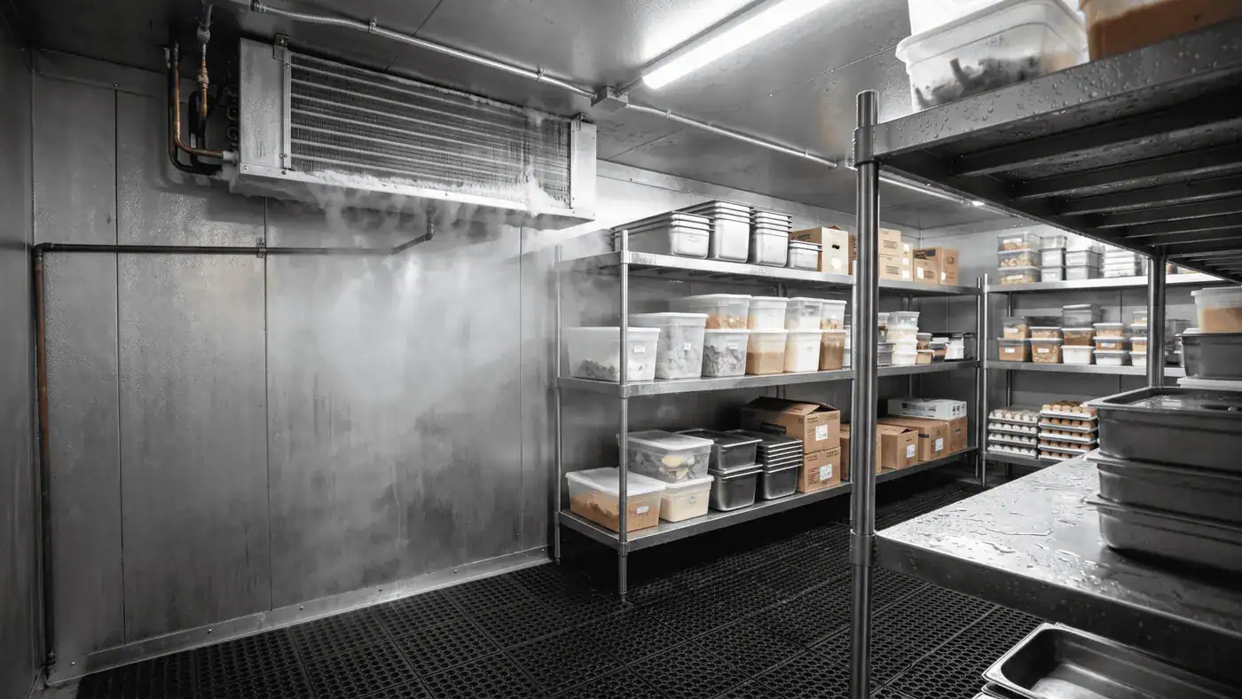
A coil cooler is a heat exchanger that removes heat from air by circulating refrigerant, chilled water, or glycol through finned tubes while air moves across the coil surface.
The term coil cooler sounds specific, but buyers use it for several different products. Some buyers reverse the words and search for a cooler coil, particularly for walk-in cooler replacement work. Treat that as a naming variant, not as a complete specification. One request may describe a ceiling-mounted evaporator in a walk-in freezer. Another may mean a chilled-water coil inside an air handler. A third may actually refer to an outdoor dry fluid cooler. Those machines do not use the same selection data, controls, or construction.
That naming problem matters when a quotation reaches engineering. A supplier cannot select a reliable coil from a requested capacity and cabinet size alone. The thermal load, entering air condition, target leaving condition, airflow, heat-transfer fluid, operating pressure, frost risk, materials, connections, and installation limits all affect the result.
This guide gives engineers and procurement teams a practical way to classify a coil cooler, prepare its specifications, and compare proposals on the same basis. It also explains which details should remain open for supplier review instead of being guessed during purchasing.
What Is a Coil Cooler?
A coil cooler transfers heat from an air stream into a colder refrigerant or liquid inside its tubes. The coil surface may stay dry, collect condensate, or accumulate frost depending on temperature and humidity.
Most coil coolers are fin-and-tube heat exchangers. Tubes carry the cold medium. Fins increase the airside surface area. A fan or an air-handling system moves air across those fins, and heat follows the temperature difference from the warmer air toward the colder medium. In HVAC specifications, the broader phrase HVAC cooling coils may include both refrigerant and liquid coils.
That is the basic mechanism. The operating details change the product.
Cooling air without mixing the two streams
The room air and the refrigerant or chilled fluid normally stay separated by the tube wall. Heat crosses that wall, but the fluids do not mix. If the tube surface is below the air’s dew point, moisture condenses on the fins and drains into a pan. If the surface is below freezing, that moisture can become frost.
The resulting duty can include two parts:
- Sensible cooling, which lowers the air temperature.
- Latent cooling, which removes moisture by condensation.
- Freezing duty, which adds frost and defrost considerations to the thermal load.
This is why an air temperature alone is not a complete coil cooler specification. An 8 C room at moderate humidity and an 8 C process air stream with heavy moisture can impose very different demands on the same face area.
Names that buyers should separate
The language varies by industry and region. Before discussing size or price, identify what the requested term means in the actual system.
| Term | Cold medium | Common location | Primary function | Selection issue that often gets missed |
|---|---|---|---|---|
| Coil cooler / cooler coil | Refrigerant, chilled water, or glycol | Cold room, cabinet, duct, or air handler | General term for cooling air through a coil | The term does not identify the system type |
| Evaporator coil | Boiling refrigerant | Refrigeration cabinet, unit cooler, or DX air handler | Absorb heat as refrigerant evaporates | Refrigerant, saturation condition, superheat, and circuiting |
| Unit cooler | Usually direct-expansion refrigerant | Walk-in cooler, freezer, warehouse, or process room | Cool and circulate room air as a packaged fan-coil assembly | Air throw, frost, defrost, drain routing, and fan arrangement |
| Chilled-water coil | Water or water-glycol mixture | Air handler, process duct, or fan-coil unit | Transfer air heat into pumped liquid | Fluid concentration, flow, temperature rise, and pump pressure drop |
| Dry fluid cooler | Water-glycol or process liquid | Outdoors | Reject liquid heat to ambient air | Ambient design point, fan energy, sound, and freeze protection |
| Condenser coil | Condensing refrigerant | Outdoor or machine compartment | Reject system heat while refrigerant condenses | Condensing temperature, ambient air, subcooling, and heat rejection |
A condenser coil is therefore not interchangeable with an evaporator-style coil cooler. One rejects heat; the other removes heat from the space or process being cooled. Domi’s article on the refrigerant cycle and coil roles provides a useful system-level view of that distinction.
Procurement check: Put the system type in the first line of the RFQ. “Ceiling-mounted DX unit cooler for a freezer” is actionable. “Need a 10 kW coil cooler” leaves too many design decisions unresolved.
Main Coil Cooler Types and Construction Options
The main coil cooler categories are direct-expansion coils, chilled-water or glycol coils, and fan-equipped unit coolers. Choose the category from the refrigeration circuit and application before comparing materials or dimensions.
No single construction is best for every job. A compact direct-expansion coil can suit an OEM cabinet. A pumped-glycol coil may make more sense where refrigerant must stay outside an occupied or process area. A packaged unit cooler solves both heat transfer and room-air movement, but it adds fan, defrost, drain, sound, and service requirements.
Direct-expansion refrigerant coils
A direct-expansion coil, often shortened to DX coil, receives liquid-vapor refrigerant through an expansion device and distributor. The refrigerant boils inside multiple circuits as it absorbs heat from the passing air. Correct distribution matters because an underfed circuit gives away surface area, while an overfed or poorly controlled circuit can threaten compressor operation.
A DX request should identify at least:
- Refrigerant or refrigerant candidates
- Evaporating or saturated suction temperature at the stated condition
- Required superheat basis and control approach
- Total and sensible load, if both are relevant
- Entering air dry-bulb and humidity condition
- Airflow and allowable airside pressure drop
- Distributor, connection, and circuit preferences, if fixed by the system
Refrigerant cannot be treated as a blank line to fill later. Pressure, heat-transfer behavior, safety classification, oil return, component approvals, charge limits, and regulations can affect the design. The EPA SNAP refrigeration and air-conditioning listings organize substitutes by end use, while ASHRAE explains that Standard 34 provides the industry system for refrigerant numbers and safety classifications on its standards and guidelines page.
Chilled-water and glycol coils
A chilled-water coil uses pumped liquid rather than evaporating refrigerant. It can simplify the coil itself, but the fluid data must be complete. Water and glycol mixtures have different viscosity, heat capacity, freeze point, and pressure-drop behavior. A proposal based on pure water should not be compared directly with one based on a concentrated glycol mixture.
The useful heat calculation begins with:
Q = m x cp x delta T
For an illustrative water-side calculation, a 0.48 kg/s water flow warming by 5 K transfers about 10 kW when water’s specific heat is taken as approximately 4.18 kJ/(kg K). That figure is a calculation example, not a product rating. A real selection still needs the airside condition, fouling basis, fluid properties at operating temperature, and allowable pressure drop.
Glycol percentage and type should be written explicitly. “Glycol coil” is incomplete because a 20% propylene-glycol mixture does not behave like a 40% ethylene-glycol mixture. If the concentration may change during operation, state the design concentration that the supplier must use.
Fan-equipped unit coolers
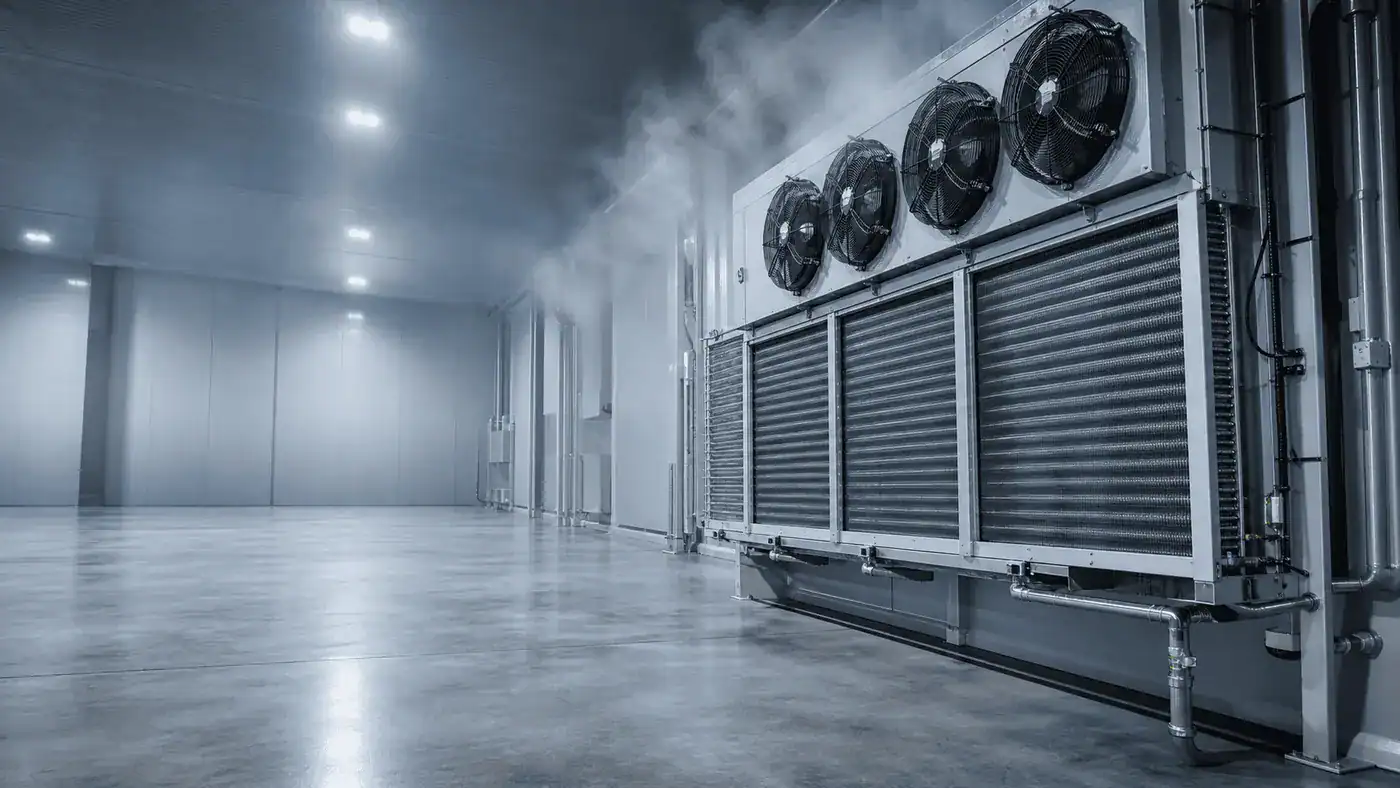
A unit cooler combines the heat exchanger with fans, casing, drain pan, and often a defrost system. It is common in walk-in coolers, freezers, food processing rooms, refrigerated warehouses, and other spaces where the equipment must cool and circulate room air.
The coil is only one part of its performance. Buyers also need to review:
- Fan quantity, airflow, external resistance, motor type, voltage, and controls
- Air throw and placement relative to doors, racks, aisles, and occupied work zones
- Drain-pan geometry, drain connection, trap, slope, and low-temperature protection
- Defrost method, termination control, and expected frost load
- Guarding, access panels, cleaning approach, and service clearance
- Sound limits where people work near the equipment
Two units with the same nominal capacity may behave differently in the room because their air patterns, fin spacing, fan control, and defrost logic differ. A dense fin pack can provide more surface in a compact envelope, yet it can also collect frost or debris faster. More face area may lower velocity and airside pressure drop, but it requires more physical space.
| Type | Best fit | Main specification inputs | Main trade-off | Typical procurement mistake |
|---|---|---|---|---|
| DX refrigerant coil | Compact refrigeration systems and direct refrigerant circuits | Refrigerant, evaporating condition, superheat basis, load, airflow, humidity, circuiting | Compact heat transfer versus refrigerant distribution and control complexity | Quoting capacity without refrigerant or saturation condition |
| Chilled-water coil | Central chilled-water HVAC and stable process cooling | Fluid type, concentration, entering/leaving temperatures, flow, load, pressure drop | Easier separation from refrigerant system versus pump energy and freeze protection | Treating water and glycol selections as equivalent |
| Brine or glycol coil | Low-temperature secondary loops and applications needing freeze margin | Exact fluid, concentration, temperature, flow, viscosity, material compatibility | Freeze protection versus lower heat capacity and higher viscosity | Omitting the design concentration |
| Unit cooler | Walk-ins, freezers, cold rooms, and refrigerated workspaces | Room load, room condition, refrigerant, airflow, air throw, frost, defrost, drainage | Packaged room cooling versus fan, defrost, sound, and maintenance requirements | Comparing only nominal capacity and cabinet width |
| Custom replacement coil | Existing air handler, cabinet, or OEM machine | Verified dimensions, rows, fin spacing, tube pattern, connections, performance point | Fast retrofit potential versus risk from incomplete field measurements | Copying overall size but missing handedness or connection centerlines |
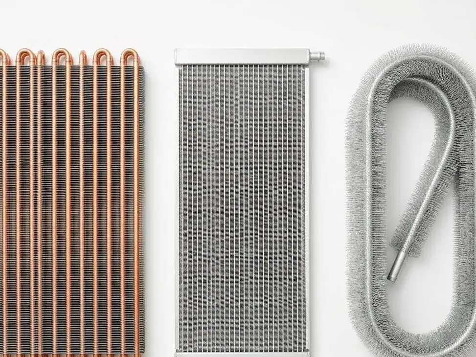
Material choices come after the system category is clear. Copper tubes and aluminum fins are common, but stainless components, coated fins, alternative tube materials, heavier casings, or special drain-pan materials may be appropriate in corrosive, washdown, food, marine, or industrial environments. The tube material and fin material should both appear in the submittal. Compatibility must be checked against the actual fluid, cleaning chemicals, contaminants, temperature, and required service life.
Domi publishes both a copper-tube fin evaporator and an aluminum-tube fin evaporator. Those pages are useful construction references, but a material family alone does not establish fitness for a specific refrigerant, pressure, duty, or environment. Request a project review for those points.
Coil Cooler Applications by System and Industry
A coil cooler can serve cold storage, food display, HVAC, heat pumps, OEM cabinets, and process equipment. The application defines the temperature, moisture, hygiene, corrosion, airflow, and maintenance constraints.
Calling every job “comfort cooling” hides the conditions most likely to cause a selection failure. A supermarket display needs stable product temperature and low visual disruption. A freezer unit cooler must manage frost and drainage below freezing. A process coil may face oil mist, dust, chemicals, or a narrow leaving-air tolerance.
Walk-in coolers, freezers, and cold rooms
In a walk-in room, the unit cooler has to remove more than wall and roof heat gain. The load can include product pull-down, infiltration through doors, people, lights, fan motors, forklifts, and defrost. Door use can change both sensible and latent load. A busy loading area is not thermally equivalent to a storage room with limited access.
Cold-room selection should document:
- Room dimensions, insulation assumptions, and surrounding ambient condition
- Product type, incoming product temperature, target temperature, and pull-down time
- Door dimensions, opening frequency, traffic pattern, and infiltration control
- Internal electrical, people, and equipment loads
- Room temperature and allowable variation
- Humidity target or product dehydration concern
- Defrost frequency, condensate drainage, drain routing, and frost exposure
Location affects performance after selection. Short-circuiting occurs when discharge air returns to the unit before sweeping the room. Racks can block throw. A unit directly over a frequently opened door can see a concentrated moisture load. Service access that looked adequate on a plan may disappear after piping, cable trays, sprinklers, or storage racks are installed.
Food display, commercial refrigeration, and OEM equipment
When a buyer asks for a cooler coil for a display case or OEM cabinet, the coil sits inside a constrained product. Face area, fan power, condensate management, noise, and packaging compete for the same limited space. A low coil face velocity can reduce pressure drop and moisture carryover, but it may require a larger coil. A deeper coil may increase heat-transfer surface, yet it can also add airside resistance and make cleaning harder.
These projects benefit from a drawing-led review. Provide the dimensional envelope, airflow path, fan curve or operating point, connection zones, drain location, sensor positions, mounting method, and access sequence. If a supplier is replacing an established part, include the original performance point as a reference but do not assume the old geometry is optimal for a new refrigerant, fan, or operating condition.
The U.S. Department of Energy advises operators of commercial refrigerators and freezers to keep coils clean and maintain adequate space for airflow over heat-exchange surfaces in its commercial refrigeration purchasing guidance. That maintenance point should influence the initial layout: a coil that cannot be reached or cleaned predictably will not hold its catalog condition for long.
Air handlers, heat pumps, and process cooling
In an air handler, the coil cooler is part of a larger fan and duct system. Airside pressure drop affects fan duty. Leaving-air temperature and moisture affect downstream comfort or process control. Face velocity, bypass, casing leakage, drain-pan design, filter condition, and fan control can all change delivered performance.
A process application may place different priorities on the selection:
- Tight leaving-air temperature for product consistency
- Low pressure drop to protect an existing fan or pump
- Corrosion resistance for a known contaminant
- Wide fin spacing for dirty air or washdown access
- Redundancy or staged capacity for continuous production
- Removable sections, access doors, or cleaning clearance
For HVAC-related applications, Domi’s HVAC and heat pump solutions page is the appropriate commercial route. For cold-room and refrigeration duties, the commercial refrigeration coil range is a closer starting point.
Specifications That Control Coil Cooler Performance
Reliable coil cooler selection requires a matched set of airside, refrigerant or fluid-side, mechanical, environmental, and control inputs. Capacity alone cannot define the coil.
A good specification tells the supplier what the coil must do and what limits it must respect. It does not prescribe every circuit detail unless the buyer has a validated reason to freeze that design. This leaves room for thermal selection while protecting the interfaces that matter to the equipment and site.
Cooling load and air condition
State the required total capacity at the design condition. If moisture removal matters, also state sensible capacity, entering humidity, or both entering dry-bulb and wet-bulb temperatures. For a cold room, provide room design temperature and the load calculation basis. For a duct coil, provide entering and required leaving-air states.
Capacity units must be unambiguous. One refrigeration ton equals 12,000 Btu/h, which is approximately 3.517 kW. A request for “10 tons” therefore represents roughly 35.17 kW of refrigeration capacity, but that conversion does not establish coil size. The temperature difference, humidity, refrigerant or fluid condition, and airflow still control the selection.
Airflow should be a measured or designed quantity, not a casual estimate from fan nameplate power. Where air distribution is sensitive, include the allowable face velocity range or request that the supplier report it. The proposal should state both selected airflow and airside pressure drop at the same density or correction basis used in the system design.
Refrigerant or liquid-side condition
For a DX coil cooler, specify refrigerant and the evaporating condition. If the system uses glide, the proposal should say which temperature basis is used. Also state liquid condition if it affects the selection, superheat basis, distributor expectation, connection orientation, and allowable refrigerant-side pressure drop where relevant.
For a liquid coil, specify:
- Fluid name and glycol type
- Concentration by the required convention
- Entering and leaving fluid temperature, or entering temperature plus required duty and flow
- Design flow rate
- Allowable fluid pressure drop
- Design and operating pressure for mechanical review
- Water quality, corrosion inhibitor, or contamination information when material selection depends on it
An incomplete fluid definition can distort both thermal and hydraulic results. Higher viscosity increases pressure drop and can reduce heat transfer. That can change the number of circuits, rows, tube velocity, and pump requirement.
Fin spacing, frost, and defrost
Fin density deserves an application-specific decision. Tight spacing packs more surface into a given depth, which can help dry-coil performance. In frosty or dirty service, that same geometry may bridge sooner and restrict airflow.
For a low-temperature unit cooler, provide the expected room condition, moisture sources, door traffic, product load, and defrost strategy. The supplier may need to coordinate fin spacing, coil depth, fan operation, heater arrangement, drain-pan heat, drain-line protection, and defrost termination. Off-cycle defrost may work in some above-freezing applications; electric, hot-gas, water, or other methods require a system-level decision and compatible controls.
Defrost is not free cooling capacity. During defrost, the coil may stop cooling and add heat to the space. A load and equipment schedule should account for the operating sequence rather than assuming continuous nameplate output.
Construction, geometry, and interfaces
Mechanical data protects fit and serviceability. Include overall length, height, depth, mounting points, allowable weight, access side, connection zones, drain position, and shipping constraints. For replacement coils, record dimensions from fixed datum points instead of relying on a photograph with no scale.
The following details frequently cause field rework:
- Left-hand versus right-hand connections viewed from different reference sides
- Header centerlines that conflict with casing or access panels
- Connection types that do not match site piping practice
- Casing flanges or mounting holes measured from an inconsistent datum
- Drain outlets without enough fall or trap clearance
- Coil pull space blocked by permanent equipment
- Fan or heater electrical data omitted from the mechanical RFQ
Material and coating requests need a named exposure. “Corrosion resistant” is not a testable specification. Describe salt, acid, alkaline cleaner, food residue, sulfur compounds, ammonia atmosphere, washdown routine, humidity, or outdoor exposure as applicable. Then ask the supplier to state the proposed materials and the compatibility basis.
Design pressure, testing, and documentation
Operating pressure and design pressure are not interchangeable. The required design basis depends on refrigerant or fluid, maximum temperature, equipment category, jurisdiction, applicable code, and system protection. Ask the supplier to identify the design standard, test method, test pressure, and documentation included in the offer. Do not infer these from tube material alone.
Refrigerant handling also has regulatory implications. In the United States, EPA Section 608 covers technician certification and refrigerant management topics; the current resources are available on the EPA Section 608 portal. Equipment selection does not replace installation and service compliance.
How to Select and Compare Coil Cooler Proposals
Select a coil cooler by fixing the design condition, setting acceptable pressure drops and mechanical limits, then comparing every supplier at that same point. Nominal capacity alone is not a fair comparison.
The cleanest process separates required inputs from supplier-selected outputs. The buyer owns the application, interfaces, and acceptance criteria. The coil manufacturer owns the proposed geometry and must disclose the conditions behind its performance.
Step 1: Define the system and design point
Start with one sentence that identifies the equipment: DX evaporator coil for an OEM cabinet, glycol coil for a process air handler, or ceiling-mounted unit cooler for a freezer. Then attach the design condition.
For systems with several operating points, identify which one controls physical size and which one controls turndown, frost, or pressure drop. A coil selected only at peak summer load may behave poorly at low-load, low-airflow, or high-humidity conditions. Ask for secondary-point checks when they change the control or reliability decision.
Step 2: Lock the comparison basis
Give every bidder the same load, entering conditions, airflow, refrigerant or fluid data, allowable pressure drops, dimensional limits, and material exposure. If a supplier proposes a different assumption, require it to be listed as a deviation.
| Comparison field | Buyer supplies | Supplier reports | Why it must stay visible |
|---|---|---|---|
| Thermal duty | Required total and sensible load, if applicable | Selected total and sensible capacity | Prevents excess latent or sensible assumptions from hiding a shortfall |
| Air condition | Entering state and required leaving state or room condition | Actual leaving state at selected airflow | Confirms that capacity produces the required air result |
| Airflow | Design airflow and allowable range | Selection airflow, face velocity, and airside pressure drop | Connects coil performance to fan duty and distribution |
| Refrigerant or fluid | Exact refrigerant, or liquid type and concentration, with temperatures | Circuit or flow selection and medium-side pressure drop | Exposes incompatible assumptions and pump or compressor impact |
| Geometry | Maximum envelope, connection zones, mounting, access limits | Rows, fin spacing, face area, casing, connections, weight | Confirms fit without hiding performance geometry |
| Frost and defrost | Room condition, moisture sources, operating schedule, method constraints | Proposed fin spacing, defrost arrangement, and control requirements | Shows whether low-temperature performance is maintainable |
| Materials | Exposure, cleaning chemicals, required interfaces | Tube, fin, casing, drain-pan, coating, and fastener materials | Makes corrosion claims specific enough to review |
| Rating basis | Required standard or project method | Software or rating method, tolerances, and exclusions | Allows an engineer to reproduce the comparison assumptions |
| Documentation | Drawing, submittal, test record, and compliance needs | Included documents and hold points | Prevents documentation gaps from appearing after the order |
Price should be compared only after these fields line up. A lower-cost coil may simply have a higher pressure drop, smaller face area, different glycol concentration, warmer evaporating condition, or excluded defrost package.
Step 3: Review energy and system effects
The coil cooler influences other equipment. High airside pressure drop raises fan demand. High liquid-side pressure drop raises pump demand. An unfavorable DX selection can affect compressor suction condition and control stability. Frost raises pressure drop during operation, not just at the clean rating point.
Ask what happens away from the design point:
- Does airflow remain acceptable as the coil gets wet or frosted?
- Can fan speed be reduced without losing refrigerant distribution or air throw?
- How does glycol concentration affect pressure drop at the lowest fluid temperature?
- Does the selected circuit support the expected capacity range?
- Is the drain and defrost sequence compatible with the site controls?
These questions turn a catalog selection into a system review. They are especially valuable when two proposals use different coil depths, fan arrangements, or media conditions.
Step 4: Confirm installation and service access
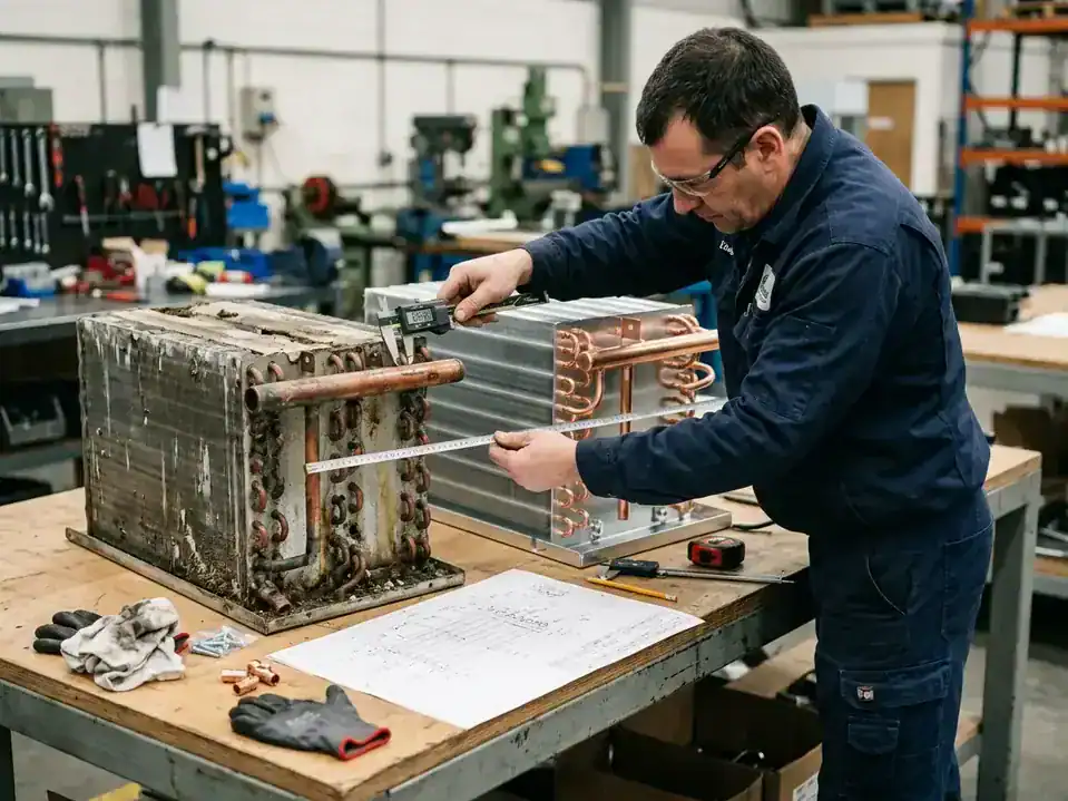
For a replacement cooler coil, measure before removal when possible and photograph every interface with a scale in the frame. Record overall casing dimensions, finned length and height, rows deep, tube pattern, fin spacing, header dimensions, connection size and type, connection centerlines, drain location, mounting holes, access side, and airflow direction.
A drawing is stronger than a photo set. Mark the viewing direction used for left and right. Identify dimensions that are fixed by the equipment and those that can change. If the old coil failed, include the failure location and operating history; reproducing the same material and geometry may reproduce the same problem. The ASHRAE handbook chapter on insulation systems also documents why below-dew-point equipment needs careful vapor, condensation, and insulation control around the connected system.
Service access belongs in the purchase review. Confirm that filters, fan guards, drain pans, heaters, sensors, and the coil face can be reached after installation. A removable panel is not useful if piping crosses it. A pull-out coil needs a clear path equal to or greater than the removal dimension.
Common selection mistakes
Several shortcuts create avoidable rework:
- Selecting by capacity and external dimensions only. The omitted air and medium conditions can change the required surface and circuits.
- Using room temperature as the only air input. Humidity and infiltration influence condensate, frost, and latent duty.
- Comparing different rating conditions. A warmer evaporating temperature or different glycol concentration can make one proposal look better on paper.
- Ignoring pressure drop. Capacity can be achieved at an air or fluid resistance the existing fan or pump cannot support.
- Specifying a coating without the exposure. The supplier cannot assess compatibility from a generic adjective.
- Freezing old geometry without a performance check. A like-for-like envelope may be necessary, but internal circuiting and materials still need engineering review.
- Treating defrost as an accessory. Frost behavior changes airflow, capacity, drainage, energy, and operating availability.
Replacement, Maintenance, and Service-Life Factors
Coil cooler life depends on materials, environment, cleaning, airflow, drainage, vibration, frost control, and operating conditions. There is no responsible universal service-life number.
The useful question is not “How many years does a cooling coil last?” without context. It is “Which failure mechanisms apply here, and how will the design and maintenance plan control them?”
Conditions that shorten life
Corrosion can start from the outside, inside, or at dissimilar-material interfaces. Airborne salt, acids, sulfur compounds, cleaners, process residue, and persistent condensate all matter. Fluid chemistry and oxygen ingress affect liquid coils. Poor drainage leaves surfaces wet. Vibration can fatigue tubes or connections. Repeated freeze events can deform or rupture water circuits.
Airside fouling changes performance before the coil leaks. Dust and fibers block fin passages, reduce airflow, increase pressure drop, and insulate the heat-transfer surface. Bent fins create local restriction. Oil films can capture more dirt. In freezing service, incomplete defrost can let ice spread beyond the coil into the pan or fan area.
Inspection should look for patterns, not just obvious holes:
- Uneven frost across circuits
- Oil staining near refrigerant leaks
- Green, white, or dark corrosion products
- Crushed fins or dirty leading edges
- Standing water or biological growth in the pan
- Repeated heater, sensor, or defrost termination faults
- Fan vibration, guard contact, or motor overheating
- Rising approach temperature or longer run time at similar load
Maintenance access starts in the drawing
Cleaning method affects spacing and materials. A coil exposed to flour dust, fibers, grease, or food residue needs a realistic access and washdown plan. High-pressure cleaning can damage thin fins, so the procedure and tools should match the construction. Chemical cleaners need a compatibility check and a complete rinse where required.
Drain systems deserve regular attention. Verify pan slope, clear the outlet, inspect traps, and confirm low-temperature heat where the design requires it. Water that cannot leave the unit can refreeze, overflow, or carry contamination into the room.
For refrigerant circuits, leak detection and repair must follow applicable regulations and site procedures. For water and glycol circuits, check concentration, inhibitor condition, strainers, vents, and evidence of freezing or internal corrosion. Maintenance records help distinguish a one-time blockage from a recurring design or control problem.
Coil Cooler Design Priorities for 2026 and Beyond
Current coil cooler design priorities center on refrigerant transition, lower system energy, verifiable rating conditions, maintainability, and better operating data. These priorities increase the value of a complete RFQ.
The geometry still matters, but selection is becoming more system dependent. Refrigerant choices affect pressure, safety classification, component availability, charge, controls, and service practice. Fan and pump energy can outweigh a small improvement in coil purchase price. Owners also expect clearer submittals and easier comparison between design and measured operation.
Refrigerant and system choices will stay linked
EPA SNAP lists acceptable and unacceptable substitutes by refrigeration and air-conditioning end use. That structure is a reminder that a refrigerant decision belongs to a defined application, not a generic coil request. A 2026 project should identify the regulatory jurisdiction, end use, refrigerant, charge strategy, safety controls, and service plan before freezing coil connections or circuiting.
Lower refrigerant charge can be a valuable system objective, but it should not be treated as an isolated marketing number. Coil volume, receiver strategy, piping, defrost, controls, service access, and operating stability all interact. Ask suppliers to state selection assumptions and refrigerant-side volume when it is a project requirement.
Efficiency needs a system boundary
A larger face area can reduce air velocity and pressure drop, but it increases material and space. More rows may raise capacity in a fixed face area, but they can add air resistance and cleaning difficulty. Higher liquid velocity may improve heat transfer while increasing pump pressure drop. There is no free adjustment.
The practical 2026 comparison should include:
- Coil capacity at the stated design point
- Fan, pump, or compressor impact created by pressure drop and operating condition
- Part-load control and fan-speed strategy
- Frost and defrost energy for low-temperature applications
- Access time and consumables needed for cleaning
- Expected monitoring points, such as entering/leaving temperatures and pressure drop
Digital selection files are useful only when their assumptions travel with the result. Keep the software version or rating basis, input sheet, output sheet, drawing revision, and approved deviations together. That record makes later troubleshooting and replacement much faster.
Coil Cooler FAQ
The answers below resolve the most common coil cooler terminology, sizing, maintenance, and purchasing questions. Each answer ends with the decision a buyer should carry into the RFQ.
What is a coil cooler?
A coil cooler removes heat from air through finned tubes carrying refrigerant, chilled water, or glycol. It may be a bare coil inside an air handler or a packaged unit with fans, casing, drain pan, and defrost components. The name alone does not identify the medium or product category. Bottom line: state whether the project needs a DX evaporator, liquid coil, or fan-equipped unit cooler.
What do cooling coils do?
Cooling coils lower air temperature and may also remove moisture. Heat crosses the fins and tube wall into a colder fluid or evaporating refrigerant. When the surface is below the dew point, condensate forms; below freezing, frost can form. Bottom line: provide entering temperature and humidity, not temperature alone.
Is a coil cooler the same as an evaporator coil?
Sometimes, but not always. A DX evaporator is a coil cooler because refrigerant evaporates inside it while cooling air. A chilled-water coil also cools air but has no refrigerant evaporation inside the coil. Bottom line: name the heat-transfer medium and system type in the inquiry.
What is the difference between a coil cooler and a condenser?
A coil cooler absorbs heat from the cooled air, while a condenser rejects system heat to another sink. Their refrigerant conditions, controls, design temperatures, and applications differ. Bottom line: do not substitute a condenser selection for an evaporator or chilled-fluid cooling duty.
What is a cold coil?
A cold coil is an informal name for any coil with a surface colder than the air around it. The phrase may describe an evaporator, chilled-water coil, or dehumidifying coil, but it gives no design condition. Bottom line: replace “cold coil” with measurable air and medium temperatures in the RFQ.
How long do cooling coils last?
There is no universal lifespan for a cooling coil. Material compatibility, corrosion exposure, water or refrigerant condition, cleaning, vibration, drainage, frost, and maintenance all affect life. A clean indoor coil and a coil exposed to salt or aggressive wash chemicals cannot share a credible generic estimate. Bottom line: identify the failure environment and request compatible construction.
What information is needed to size a coil cooler?
Sizing needs load, airflow, entering and target air conditions, refrigerant or fluid data, allowable pressure drops, and mechanical limits. Low-temperature applications also need frost, defrost, drainage, and operating-schedule information. Bottom line: send the operating data and dimensional drawing together.
How should buyers compare two coil cooler quotations?
Compare both proposals at identical rating conditions. Check load, airflow, entering and leaving conditions, refrigerant or glycol concentration, pressure drops, geometry, fin spacing, materials, defrost scope, fans, controls, documentation, and exclusions. Bottom line: treat any changed assumption as a deviation, not an equivalent offer.
Preparing Your Coil Cooler Request for Engineering Review
A useful coil cooler inquiry combines the application, design conditions, medium, performance limits, construction needs, and dimensional interfaces in one review package.
Start with the system type and duty. Add entering and target air conditions, airflow, refrigerant or fluid details, allowable pressure drops, frost and defrost requirements, materials exposure, design pressure basis, dimensions, connections, mounting, electrical data, service access, documentation, and required delivery destination. Attach a drawing for replacement or OEM work.
Do not fill gaps with assumed product claims. Mark unknown fields and ask the supplier to identify the information required to complete the selection. For a project-specific assessment, request an HVAC coil review and send the operating condition with the drawing. That gives engineering a defensible starting point for thermal, hydraulic, mechanical, and manufacturing review.