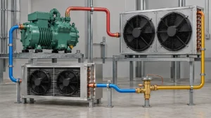
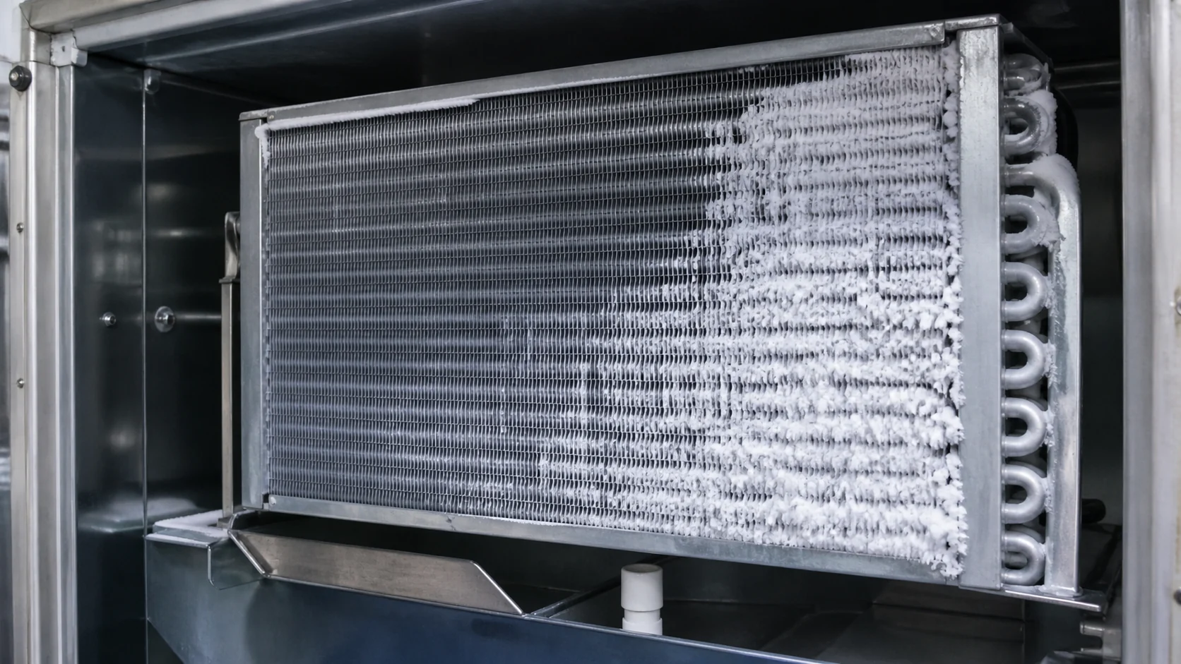
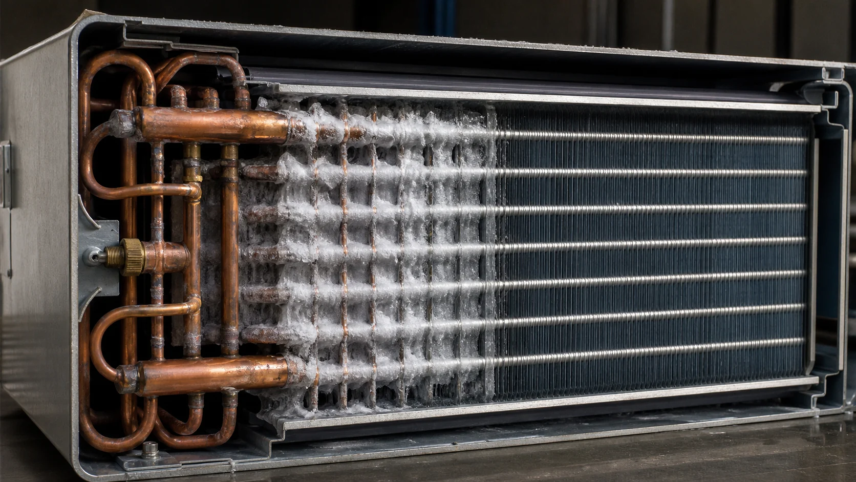
Uneven frost on an evaporator coil is a distribution symptom, not a part diagnosis. Frost may be heavier at the inlet, limited to one circuit, concentrated near an air-leak path, or absent on a section that should be cold. Before ordering a replacement coil, capture temperatures, airflow, operating condition, defrost state, refrigerant evidence, and the coil revision. A controlled record separates an airflow or moisture problem from a circuiting, charge, restriction, or defrost problem.
What uneven frost tells an engineering team
Frost forms when a cold coil surface is below the local air dew point and moisture reaches that surface. The visible pattern is therefore affected by coil surface temperature, refrigerant distribution, air velocity, humidity, infiltration, fin spacing, defrost recovery, and the position of covers, gaskets, fans, and sensors. One photograph can show where the symptom appears, but it cannot identify the failed subsystem on its own.
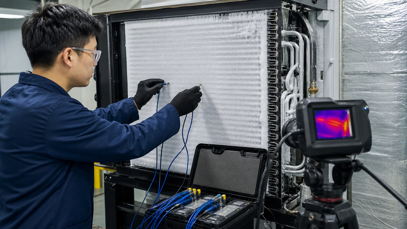
The first question is whether the pattern is repeatable. Record the cabinet or room condition, compressor and fan state, suction or evaporating condition where it is safe to do so, and the time from start-up to the photograph. A pattern that changes after a door opening or fan restart points to a different investigation than a stable inlet-only pattern under controlled conditions.
For unit coolers, AHRI describes a factory-made assembly that combines forced air circulation with heat transfer from air to refrigerant. AHRI 420 and 421 provide a rating context for defined unit cooler products, but the installed room, duct, package, moisture load, and defrost sequence still need application evidence. Use the rating point as a comparison basis, not as a substitute for an installation diagnosis. Review the AHRI unit cooler scope before copying a published rating into an RFQ.
Start with a controlled observation
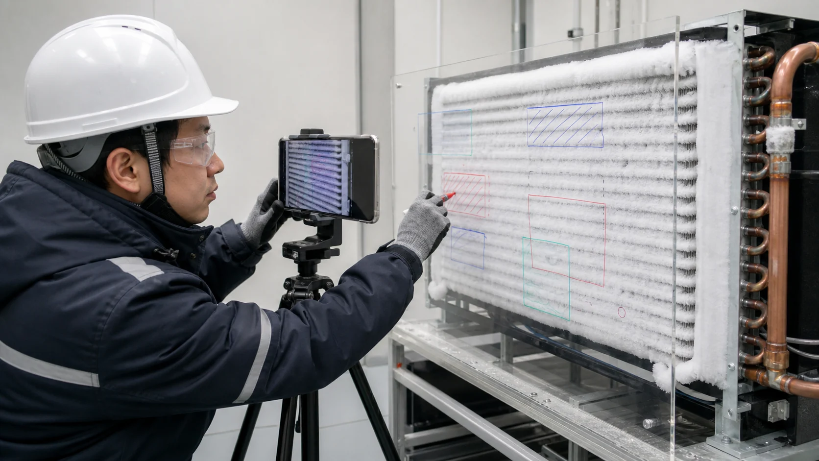
Do not scrape away frost before recording it. Photograph the full face, the inlet and outlet connections, the drain pan, the fan or shroud, and any gaps around the cover. Add a scale or a known mounting feature so the location can be compared after a change. If the system is a production appliance, record model, part number, drawing revision, refrigerant, setpoint, ambient, and the time since the last defrost.
| Observation | What it can indicate | Evidence to collect | Immediate next check |
|---|---|---|---|
| Frost only at the inlet or first circuit | Low evaporating temperature at the entry, restriction, poor distribution, or heavy local moisture | Inlet and outlet temperatures, pressure or temperature proxy, circuit map | Confirm charge, restriction, distributor, and airflow before condemning the coil |
| Frost heavier on one side of the face | Air bypass, fan or shroud issue, blocked fin area, or circuit imbalance | Face velocity map, fan rotation, cover seal, circuit identification | Check air path and compare the cold zone with the connected circuit |
| Frost stops at a repeatable tube row | Circuiting, refrigerant state, fin contact, or local heat leak | Tube route, connection direction, surface temperature by row | Review drawing, joining record, and operating condition |
| Frost returns after a short defrost | Drainage, termination sensing, heater access, moisture ingress, or incomplete melt | Defrost start and end, pan temperature, drain clearance, sensor location | Verify the complete defrost path and water removal |
| Frost pattern changes after loading or door opening | Infiltration, product moisture, package resistance, or air distribution | Door events, product load, humidity, return path, fan timing | Repeat the test at a controlled load and infiltration profile |
Separate air-side, refrigerant-side, and defrost causes
Air-side restrictions and bypass
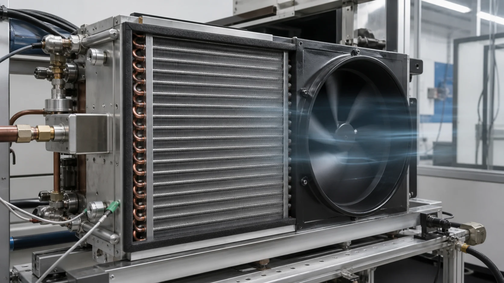
An evaporator can frost unevenly when the air does not reach the face evenly. Check fan rotation, fan speed, blade clearance, shroud position, return-air openings, filters, covers, fin damage, and gasket compression. A small bypass gap can keep one region warmer while another region receives a concentrated stream of humid air. A blocked inlet can also make the coil surface colder in the remaining open area and accelerate local frost.
Do not use a single centerline velocity as proof of uniform airflow. Map several face locations and record the measurement method. For a cabinet, inspect the air channel and shelf loading. For a cold room, document doors, strip curtains, racks, product packages, and any discharge path that short-circuits to the return.
Refrigerant distribution and circuiting
Uneven frost may be related to refrigerant distribution, a restriction, incorrect charge, a leak, oil behavior, or a circuit that does not match the approved design. Circuiting and connection direction matter because two coils with the same outside dimensions can place the coldest surface in different locations. Confirm the refrigerant, design pressure, connection size, distributor or header arrangement, tube route, and the conditions used for the original rating.
Avoid treating a frost line as a pressure reading. Use qualified measurements and the equipment procedure. A replacement coil should be compared against a controlled drawing and the operating data, not selected from length and width alone. Domi’s replacement evaporator coil guide explains why envelope, circuit, airflow, defrost interfaces, and approved performance belong in the replacement scope.
Defrost, drain, and control interfaces
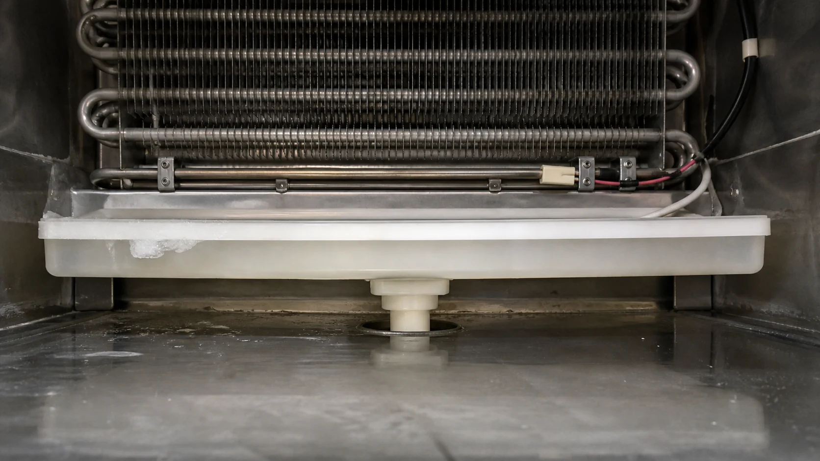
Frost that remains after a nominal defrost can spread into adjacent surfaces and change the next cycle’s airflow. Verify heater or hot-gas access, sensor or thermostat location, termination logic, pan slope, drain heat or tracing where applicable, and the path from the pan to the drain. A coil drawing should show the clearances that keep defrost heat from damaging the fin pack, liner, wiring, or insulation.
If the complaint appears only after several cycles, record the number of cycles, termination temperature or signal, fan restart timing, and the amount of residual ice. Do not assume that replacing the coil will correct a failed sensor, blocked drain, or control sequence.
Use the frost shape with temperature and airflow evidence
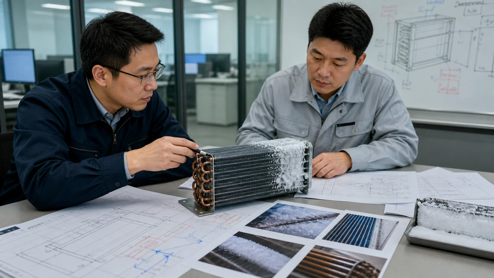
The value of a frost photograph increases when each zone is tied to a measurement and a controlled operating state. Mark the photo with circuit or tube-row references, then repeat the measurements after cleaning, defrost, fan repair, charge correction, or a drawing change. Keep the original and revised records together so a temporary improvement is not mistaken for a permanent fix.
| Frost pattern | More likely area to investigate | Evidence to collect | Release or hold decision |
|---|---|---|---|
| Inlet-heavy frost with a warm outlet | Charge, restriction, circuiting, or load condition | Qualified pressure and temperature data, leak check, circuit drawing | Hold replacement approval until the refrigerant-side evidence is closed |
| Outlet-heavy frost with weak air movement | Fan, shroud, airflow path, or sensor location | Fan current, rotation, face velocity, cover fit, sensor position | Hold the air-side interface and repeat at controlled airflow |
| Vertical strip or corner frost | Bypass, blocked fins, header path, or uneven wetting | Face map, fin condition, header and tube route, seal inspection | Approve only after the physical cause is identified |
| Frost remaining at the pan or drain | Defrost capacity, termination, drainage, or moisture ingress | Cycle log, pan temperature, drain flow, residual ice photos | Hold until the defrost and drain path clears reliably |
| Pattern changes between identical units | Variation in assembly, charge, fan, control, or material | Serial records, component lots, revision, test method | Open a variation review instead of replacing random units |
Check the coil geometry and installation interfaces
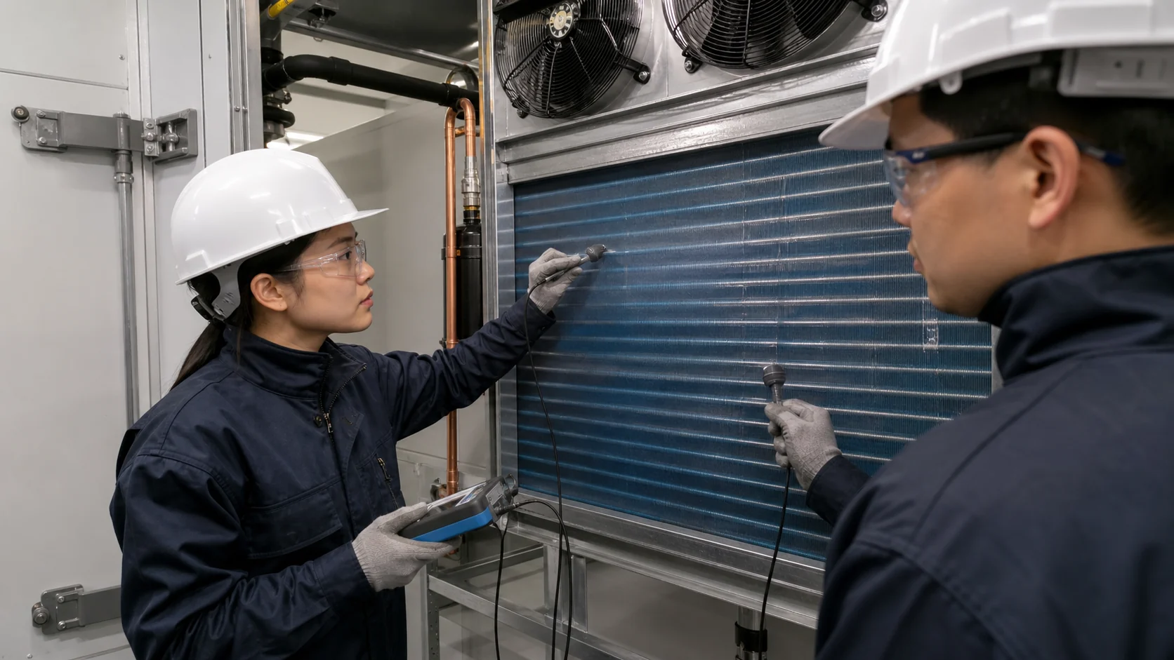
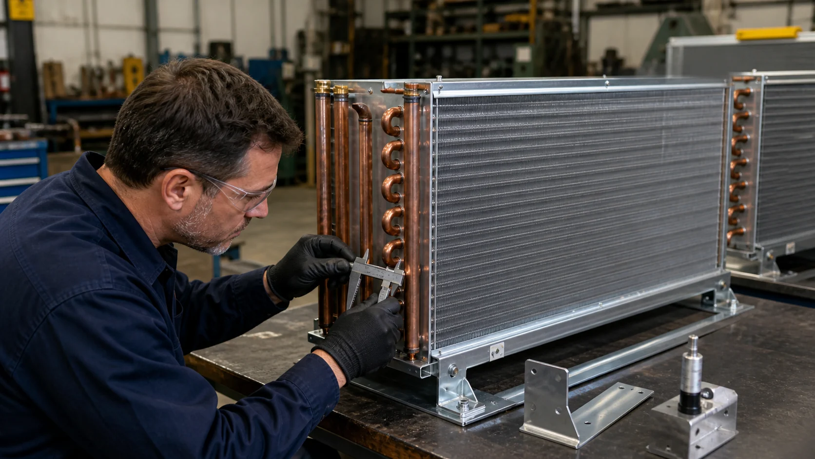
An engineering review should compare the approved drawing with the installed part and the surrounding assembly. Check fin pitch, tube diameter, rows, circuiting, headers, connection orientation, mounting points, drain outlet, heater clips, sensor contact, cover seals, and the clearances to fans and liners. A part can meet its outside dimensions and still create uneven frost if the circuit or air path is different.
| Design input | Why a mismatch can create uneven frost | Buyer record to retain |
|---|---|---|
| Fin pitch and row depth | Air resistance and moisture retention vary across the face | Released drawing, material and fin-forming record |
| Circuiting and headers | Refrigerant distribution and pressure drop shift the cold zone | Circuit diagram, connection sketch, and revision |
| Cover, shroud, and seals | Bypass air can concentrate moisture on one region | Assembly drawing, seal material, and fit-up photos |
| Defrost hardware and sensor location | Residual ice can survive near a cold or shielded area | Heater, clip, sensor, termination, and clearance details |
| Drain outlet and pan slope | Meltwater can refreeze and block the next airflow path | Drain drawing, slope check, flow test, and service access |
Build an RFQ around the evidence, not the symptom
When the investigation points to a redesign, replacement, or custom coil review, send the supplier a package that can be compared line by line. Include the application, refrigerant, operating range, capacity or heat-load basis, airflow, pressure limits, dimensions, connections, materials, coating, fin pitch, defrost method, drain arrangement, sample quantity, inspection requirements, and the observed frost pattern. Mark what is measured, what is calculated, and what remains open.
| RFQ field | Required detail | Why it protects the decision |
|---|---|---|
| Frost evidence | Annotated photos, cycle time, affected zones, and repeatability | Prevents a supplier from guessing which symptom is being solved |
| Operating condition | Refrigerant, evaporating condition, entering air, humidity, airflow, and load | Makes a thermal comparison meaningful |
| Mechanical interfaces | Envelope, mounting, connections, cover, fan, heater, sensor, and drain | Prevents a dimension-only replacement |
| Validation scope | Fit, leak, pressure, thermal, airflow, defrost recovery, and documentation | Separates a sample check from a production release |
| Commercial assumptions | Sample, pilot, recurring volume, packaging, lead time, and revision control | Keeps the quotation comparable when the design changes |
Decide whether to repair, redesign, or replace
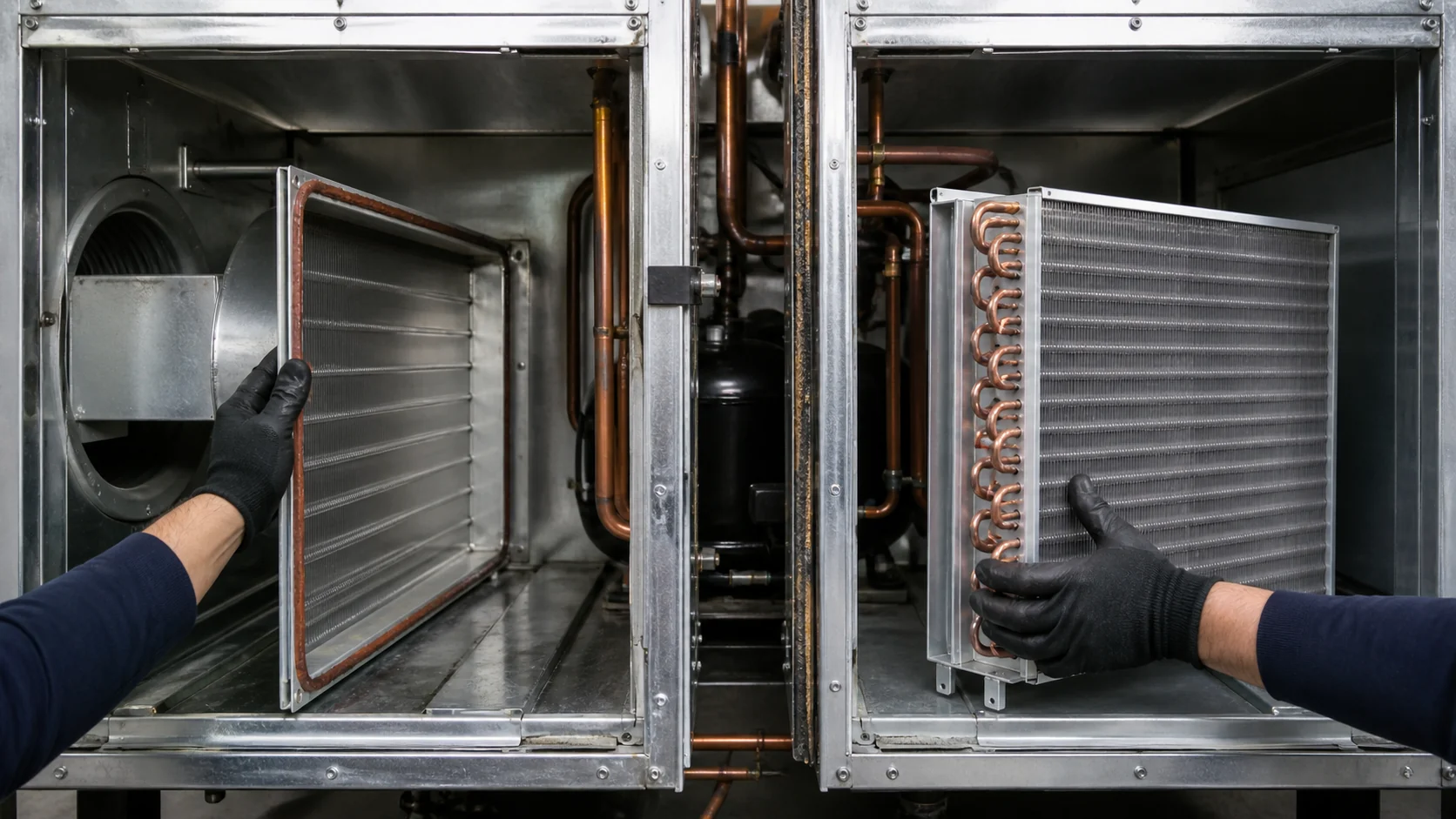
Repair is appropriate only when the cause is a serviceable issue such as a blocked air path, damaged seal, fan fault, or recoverable defrost problem. Redesign may be needed when the circuit, fin pitch, drain, heater interface, or cover cannot meet the application condition. Replacement is a sourcing decision that still requires fit, operating, test, and revision evidence. Use a stage gate so the team does not buy a new coil before proving that the old coil was the cause.
Validate the change before production release
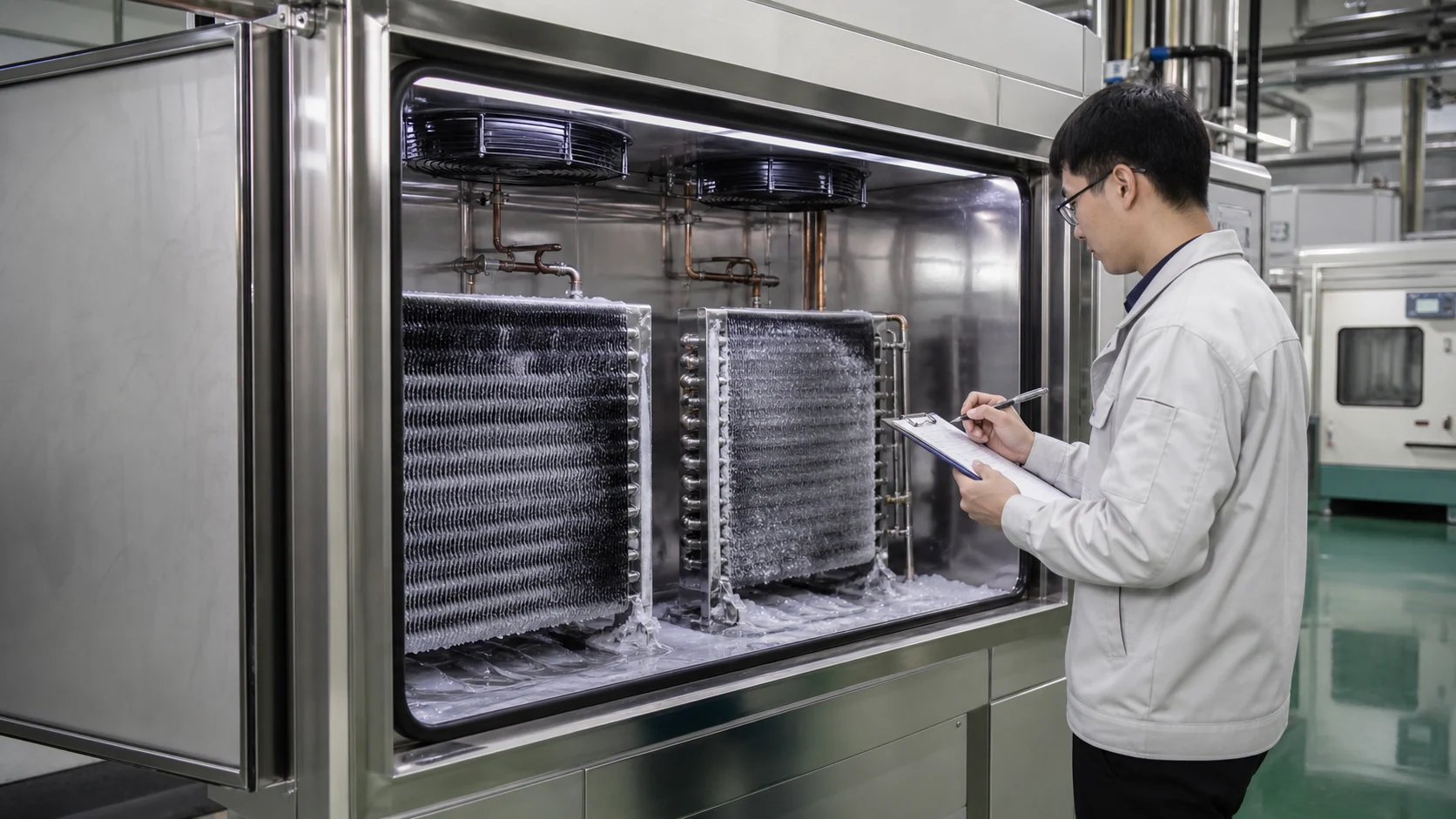
For an OEM program, validate the revised coil in the complete appliance or system, not only on a bench. Confirm the same installation, fan, control, load, humidity, defrost sequence, and measurement locations used in the acceptance plan. Record the frost pattern at the beginning and end of the test, the time to recover airflow after defrost, the drain result, and any deviation from the released drawing.
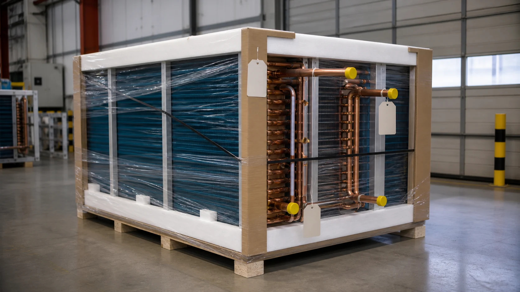
Use a production-intent sample when the decision concerns repeatability. Retain the drawing revision, material records, inspection results, test method, photos, and approval status. Domi’s custom coil fabrication service can review drawings, samples, operating data, and quantity requirements before a buyer commits to a replacement or repeat production route.
What to send to Domi for a technical review
Send the latest drawing or clear sample photos, the equipment model, refrigerant, target temperatures, capacity or heat-load basis, airflow information, pressure limits, dimensions, connections, defrost method, drain details, the affected frost photos, and the quantity or replacement requirement. If the coil is part of a multi-SKU program, identify each variant and its forecast or service need. A controlled package lets the engineering team separate an immediate troubleshooting question from a custom manufacturing request.
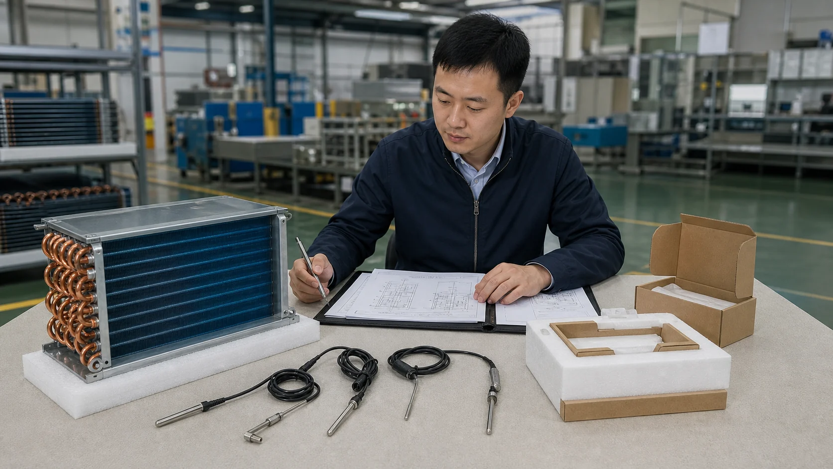
Request a custom coil quote with the drawing revision and the frost evidence attached. The goal is a traceable decision: correct the installation, repair the interface, redesign the coil, or replace it with a part that is verified in the real operating condition.
Frequently asked questions
Does uneven frost always mean the evaporator coil is defective?
No. Uneven frost can come from airflow bypass, a fan or shroud problem, moisture infiltration, defrost or drain faults, refrigerant distribution, a restriction, or an incorrect operating condition. Capture evidence before selecting a replacement.
What should be measured before a frost pattern is removed?
Record cabinet or room temperature, entering and leaving air, airflow at several face locations, compressor and fan state, the operating or evaporating condition where qualified, defrost status, and the exact frost location. Photograph the full assembly with the drawing or part number.
Can a replacement evaporator with the same dimensions solve uneven frost?
Not reliably. Circuiting, fin pitch, connections, airflow interfaces, defrost hardware, sensor location, and drain geometry can all change the frost pattern. A replacement should be matched to the released interfaces and validated in the complete system.
How can a buyer distinguish a refrigerant-side issue from an airflow issue?
Use qualified pressure and temperature evidence together with a face-velocity map, fan check, cover inspection, and circuit references. A photograph or a single surface temperature is not enough to identify a restriction, charge issue, or bypass path.
What does recurring ice after defrost usually require?
Check termination sensing, heater or hot-gas access, pan and drain clearance, fan restart timing, door or humidity load, and the location of residual ice. The coil may be fine while the defrost or drainage interface remains uncontrolled.
What should an OEM include in a custom coil RFQ for this problem?
Include the affected frost photos, cycle timing, application and refrigerant data, airflow and load basis, drawing revision, mechanical interfaces, defrost and drain details, sample and validation requirements, quantity, packaging, lead-time assumptions, and the decision the new sample must prove.