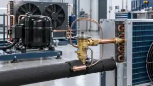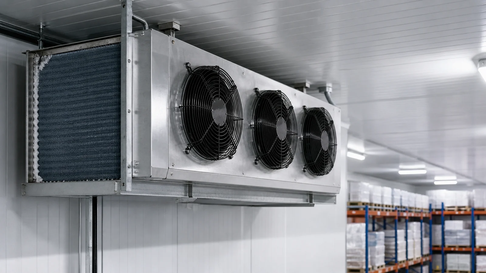
Cold room evaporator fan selection starts with the required airflow at the pressure resistance of the actual evaporator assembly. Fan diameter and free-air volume are not enough. The selection also needs a defined coil condition, room temperature, motor and control data, defrost sequence, mechanical envelope and acceptance test.
A fan can move its catalogue air volume in a test arrangement and still miss the required airflow after it is installed behind a finned coil and guard. Frost adds resistance. A venturi, grille or cramped inlet changes the air path. Low temperature affects the motor, bearings, wiring and starting behavior. Speed control can save power at part load, but reducing speed also changes air distribution and coil performance.
The fan therefore belongs in the evaporator specification, not on a separate purchasing list with only a diameter and voltage. Engineers need a duty point and operating states. Procurement needs returned curves, electrical data, mounting details and stated exclusions so proposals can be compared on the same basis.
This guide covers the fan and motor package on a cold-room evaporator. For the complete equipment decision, use Domi’s industrial refrigeration evaporator selection guide and forced-air cooler selection guide. Room layout and jet coverage are handled separately in the industrial air cooler air throw guide.
Start with airflow and static pressure at the duty point
The fan duty point is the combination of airflow and pressure at which the fan is expected to operate. On a fan curve, it is where the fan’s available pressure meets the resistance of the evaporator assembly and its air path. Change the coil, fan speed, guard, inlet clearance or frost condition, and that intersection moves.
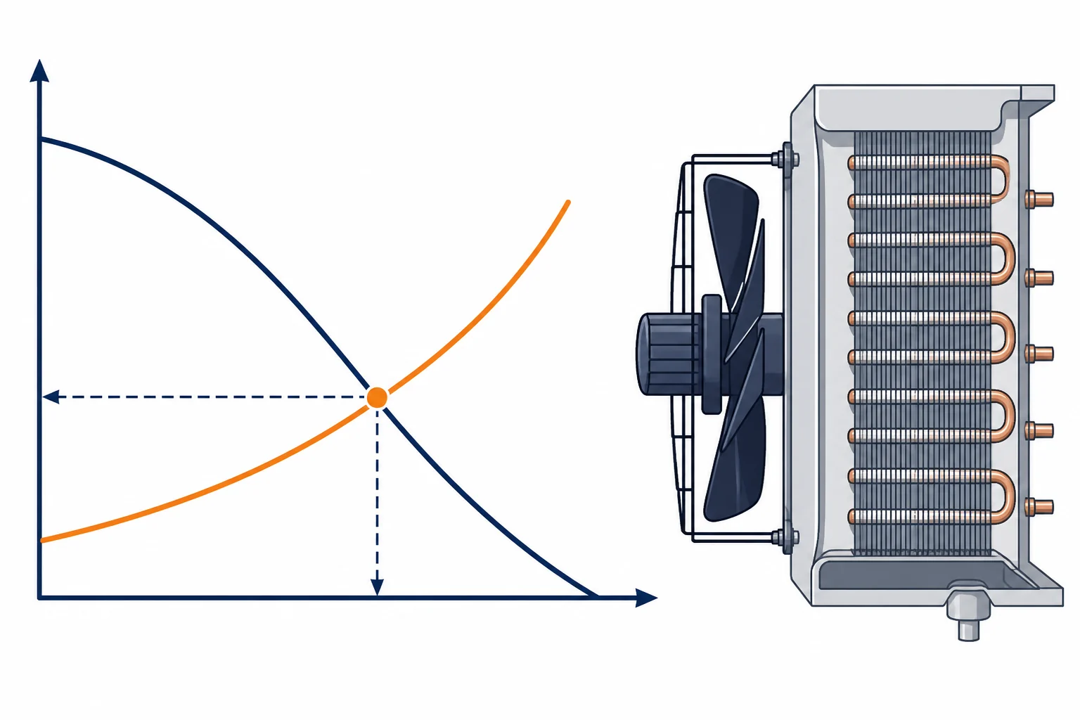
The required airflow should come from the evaporator design and room duty. It is not a value to copy from a fan with the same nominal diameter. The coil supplier or equipment designer must establish the air volume needed to deliver capacity at the stated entering-air condition, evaporating condition, fin geometry and allowable temperature difference.
The pressure requirement must use the complete unit boundary. Depending on the product, this may include:
- the clean or operating air-side pressure drop of the coil;
- the fan panel, venturi, guard and discharge grille;
- filters, duct sections, deflectors or accessories, if fitted;
- inlet and outlet clearances that create a system effect;
- an agreed allowance for frost or contamination.
Free delivery means the fan operates at zero fan static pressure. It is useful as a curve endpoint, but a fan behind an evaporator coil does not operate in free air. A proposal that lists only free-air volume leaves the main selection question unanswered.
ANSI/AMCA 210-25 and ASHRAE 51-25 set laboratory methods for fan aerodynamic ratings such as airflow, developed pressure, power, air density, speed and efficiency. ISO 5801:2017 also covers fan performance testing in standardized airways. A buyer can use these references to ask how the curve was measured. Neither standard turns a bare catalogue point into installed evaporator performance.
Recover the system boundary before comparing curves
Two fan curves can use different boundaries. One may represent a bare fan. Another may include a guard or nozzle. A third may be measured as part of a complete air cooler. Ask which components were present and whether pressure is stated as static or total pressure.
Air density also matters. A curve may be published for a reference air density rather than the actual cold-room condition. If the supplier applies a density or speed correction, the proposal should state the source curve, correction method and limits. Procurement should not have to infer these details from a motor nameplate.
The commercial refrigeration coil sizing guide explains how capacity, face velocity and air-side pressure drop interact. Fan selection should use the same coil geometry and rating point that appear in the thermal proposal. A curve prepared for a different fin spacing or row count does not prove the submitted coil and fan pair.
Treat each fan in a multi-fan unit as part of one assembly
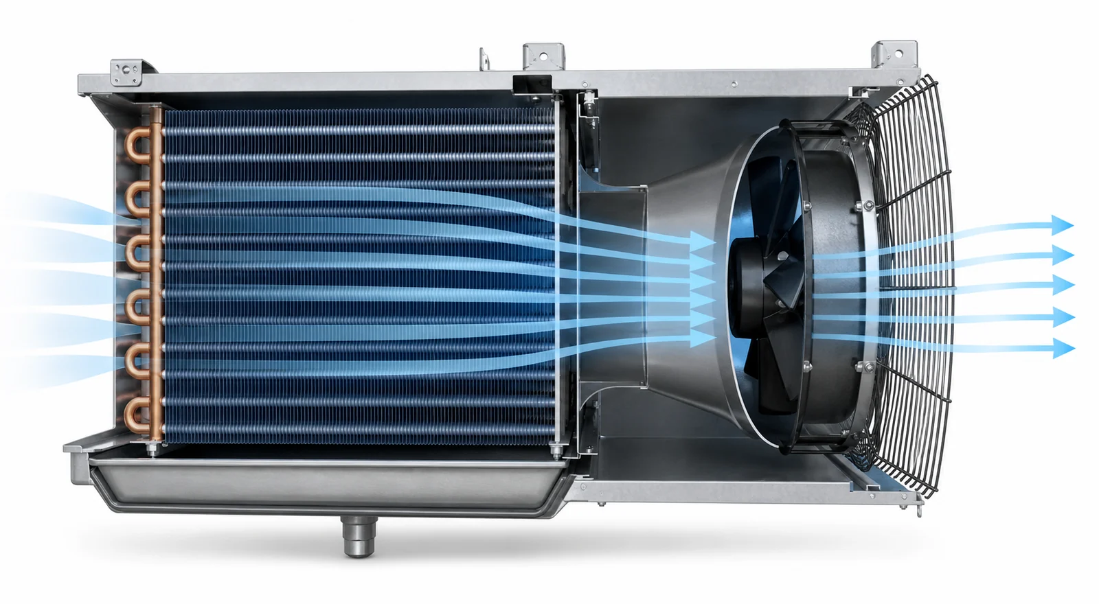
Adding the free-air volumes of three fans does not automatically give the installed unit airflow. The fans share a coil face and plenum. Their inlet zones can overlap. A failed or stopped fan may allow reverse flow through its opening. Guards and panel spacing can change how evenly the coil face is used.
For a multi-fan evaporator, request the performance of the complete arrangement or a documented method for combining the individual fans. Also define what happens if one fan is disabled. The answer may affect controls, alarms, service planning and the acceptable temporary operating condition.
Define clean, frosted, defrost and restart states
A single clean-coil duty point is rarely enough for a freezer application. The air-side resistance changes between defrosts, and fan operation may stop or change during defrost and drip time. The specification should name the states that matter rather than asking for an undefined frost allowance.
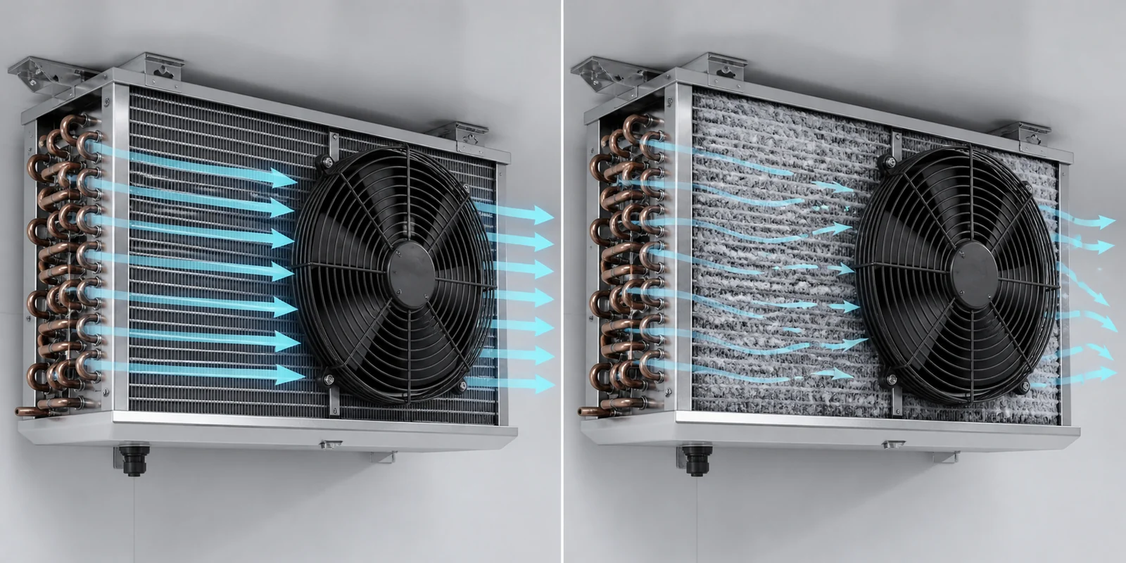
Clean and wet operation
The clean state gives a repeatable baseline. State whether the coil is dry or wet because condensate can change pressure drop and air behavior. For a cooler operating above freezing, a wet-coil point may be more representative than a dry laboratory point.
Record the air temperature, humidity basis, fan speed, voltage and coil condition with the result. A clean test is useful for incoming inspection and troubleshooting later, but it should not be presented as the only freezer acceptance condition.
Frosted operation
Frost narrows the air passages between fins. Pressure drop rises, airflow falls and the distribution across the coil face can become uneven. The exact progression depends on the coil, moisture load, operating temperatures, fan arrangement and defrost strategy. There is no universal percentage that can be applied to every evaporator.
Define a test endpoint that can be repeated. It might use elapsed operating time under stated room conditions, a measured pressure drop, an airflow limit, a frost mass or a control trigger used by the complete unit. The supplier should explain which endpoint applies and what remains outside the rating.
Defrost, drip time and fan restart
Fans are commonly coordinated with defrost so they do not distribute heat, water droplets or warm moist air before the coil is ready. The timing depends on the defrost method, drain arrangement, sensor position and controller logic. A fixed delay copied from another unit is not proof that the new assembly has drained or cooled sufficiently.
The Danfoss cold-room calculation guide treats installed fan power and electric defrost power as loads within the cold-room calculation. Danfoss evaporator-controller documentation also includes selectable fan-control behavior around thermostat and defrost operation. These examples show why controls, fan heat and defrost cannot be reviewed as unrelated items.
For the submitted unit, ask who owns the restart logic, which sensor releases the fans, whether a maximum delay is required, and what happens when the expected release condition is not reached.
Choose the fan and motor arrangement for the actual evaporator
Axial fans are common on free-delivery cold-room evaporators because they can move a large air volume through a compact panel. That does not make every axial fan interchangeable. Blade geometry, hub, venturi, tip clearance, guard, motor position and rotation direction form one air-moving assembly.
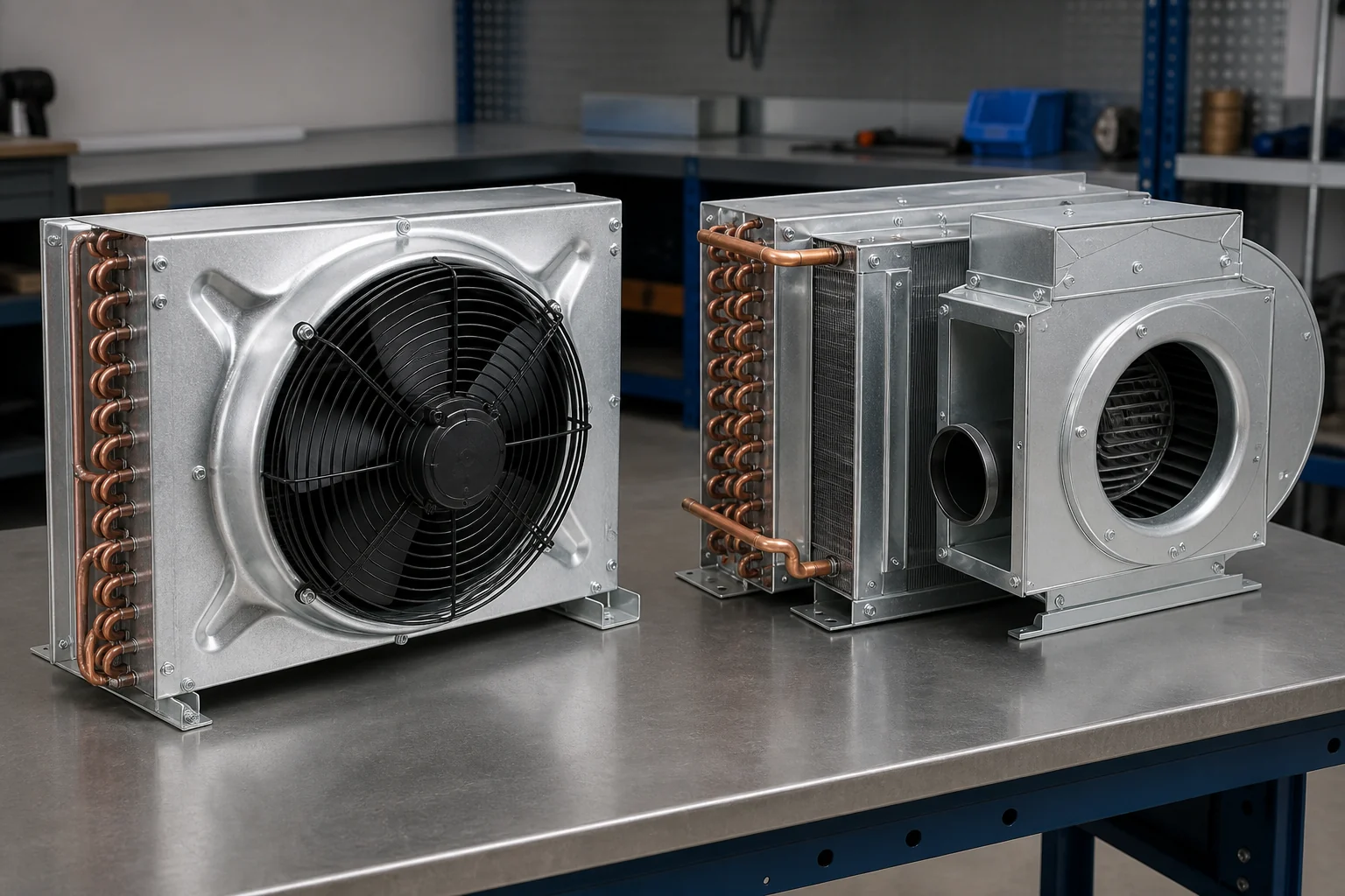
A deeper or more restrictive unit may need a fan arrangement with more pressure capability. Ducted discharge, filters or unusual accessories can also change the appropriate fan family. The choice should follow the required operating point and packaging, not a rule that one fan type fits all evaporators.
Check rotation, discharge direction and the venturi
Confirm the viewing direction used to state clockwise or counterclockwise rotation. The same word can be misread when one drawing views the motor side and another views the blade side. The approved drawing should show rotation, airflow direction, blade orientation and motor mounting.
The venturi and tip clearance deserve their own dimensions. A blade installed too far forward or behind the intended plane may lose pressure and increase noise. Excessive tip clearance can allow recirculation. Too little clearance creates a mechanical risk from tolerance, vibration, ice or handling damage.
The fan guard adds resistance and affects service access. Specify which side needs protection, the applicable safety requirement, fastener method and removal clearance. Do not remove it from the performance boundary if it will be installed on every production unit.
Separate motor-only and complete-fan sourcing
A motor quotation does not necessarily include the blade, guard, venturi, capacitor, cable, connector or mounting bracket. A complete fan quotation may still exclude the panel and unit wiring. Define the assembly boundary in the RFQ and drawing.
Domi lists an EC shaded-pole freezer fan motor and a low-noise axial fan product. These pages are starting points for a component discussion, not proof that either item fits a particular evaporator. The project still needs the required curve, voltage, frequency, temperature range, mounting and control interface.
Compare AC and EC options against the project
AC and electronically commutated motor options should be compared at the required operating points and within the complete control architecture. The labels alone do not decide the project.
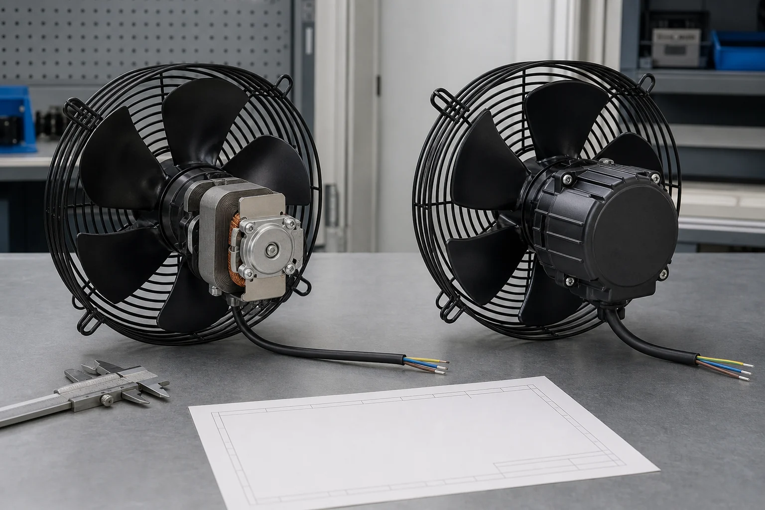
An AC shaded-pole arrangement may suit a simple fixed-speed product where cost, established supply and straightforward controls have priority. Depending on the motor, speed options may require winding choices, voltage changes or an approved external controller. Verify the actual method and its effect on heat, noise and reliability.
An EC arrangement can integrate electronic commutation and speed control. It may support a broader modulation range, control input or feedback output, but only if the selected product provides those functions. The buyer should confirm the signal type, reference ground, command range, feedback format, fault behavior and cable pinout. Do not assume that every EC motor accepts the same interface.
Compare power at matched duty, not at unmatched catalogue points
Efficiency comparisons require the same airflow, pressure, air density and accessory boundary. A lower input-power value attached to a different operating point is not a valid saving. Request power and current at the scheduled duty and at the relevant part-load points.
The fan also adds heat inside the cold room. That input becomes part of the refrigeration load. If speed reduction is planned during low load or nighttime operation, define the minimum circulation that still protects temperature uniformity and the coil. The lowest possible speed is not automatically the best control setting.
Plan electronics and replacement strategy
Electronic controls may add diagnostics and modulation, but they also change the replacement part, wiring and fault investigation. Ask whether the controller is integrated or separate, what protection is built in, how a failed unit is identified, and whether a replacement requires programming.
For either motor type, record the approved manufacturer, model or controlled drawing. A physically similar replacement can have a different curve, rotation, input power, mounting height or temperature limit. Replacement control is part of the equipment design.
Check low-temperature, moisture and defrost exposure
A motor that reaches the duty point at room temperature can still be unsuitable for a freezer. The supplier must confirm the operating and storage temperature range, starting condition, bearing system, lubrication, moisture protection and approved mounting orientation.
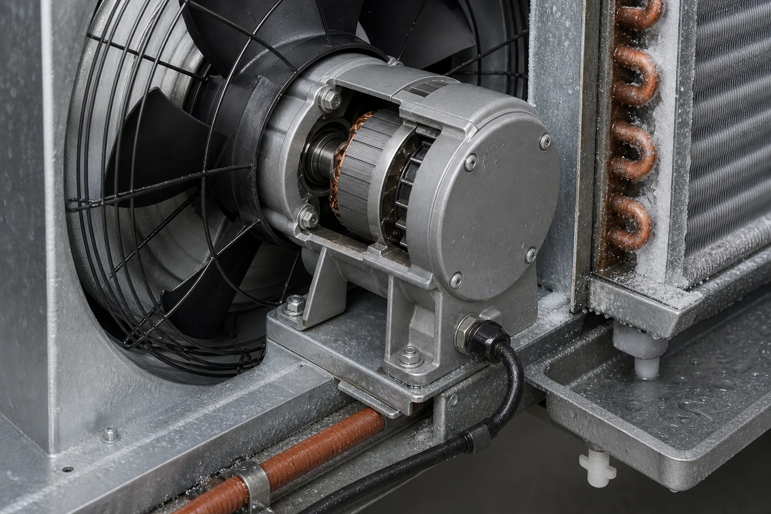
Define the cold start
State the lowest room temperature at which the fan must start, not only the normal running temperature. Include the available voltage and expected tolerance at that condition. If the unit may restart after a long off period, say so. Starting torque, capacitor behavior, control electronics and bearing drag may not match their warm-condition behavior.
Request evidence for the submitted model and assembly. A generic motor-family temperature statement is weaker than a controlled datasheet tied to the quoted item. If the project needs a witnessed test or first-article cold start, include it before production release.
Protect wiring and connectors from condensation
Moisture may come from room humidity, washdown, defrost vapor or condensation during temperature transitions. Define the exposure and cleaning practice. Ask for the motor protection rating, cable-entry method, connector sealing, insulation system and drain or weep provisions where relevant.
Route the cable so it does not rub against the guard, collect water at an unsealed entry or block service removal. Confirm cable length, conductor identification, grounding, connector mating part and temperature rating. A sealed motor with an unsealed field splice still leaves a weak point.
Review the fan’s position relative to defrost heat and water
The motor, blade, guard and cable can see radiant heat, water droplets and refreezing during a defrost cycle. Ask for the maximum exposure at their location and verify that the drain pan and coil shed water without directing it into the motor or connector.
Ice should not be allowed to bridge from the guard to the blade path. Check clearances in the installed orientation and review how the unit behaves after a partial or interrupted defrost. This is a unit-level question that a bare motor certificate cannot answer.
Coordinate speed, cycling, alarms and room behavior
Fan control changes both the evaporator and the room. Lower speed reduces airflow and usually moves the operating point on both the fan curve and system curve. Coil capacity, air temperature difference, frost pattern and room distribution can all change.
The control specification should define:
- when the fans run at full, reduced or zero speed;
- the minimum approved speed or airflow for each mode;
- the temperature and defrost states that inhibit operation;
- the feedback or current signal used to detect a failed fan;
- the response when one fan in a multi-fan unit fails;
- the restart sequence after power loss or defrost.

If the room needs a long throw or must circulate through racks, verify the reduced-speed mode against the real layout. Fan selection establishes what the unit can deliver. The room-coverage review establishes whether that delivery reaches the required zones.
An alarm should identify a useful action. A controller may detect a locked rotor, missing tachometer signal, unexpected current or temperature deviation, depending on the available hardware. Define the detectable fault and the intended response. Do not list “fan alarm” without saying what is measured.
Compare supplier proposals on one returned-data sheet
Require each supplier to return the same fields. Leave space for exceptions and deviations rather than forcing a simple compliant box. A proposal that cannot state its rating boundary should not be compared as if the missing data were equal.
| Comparison field | What the supplier should state | Why it matters |
|---|---|---|
| Fan and motor identity | Manufacturer, model, revision and assembly scope | Controls substitution and replacement |
| Duty point | Airflow, fan pressure, air density and speed | Shows the intended operating point |
| Curve basis | Test method, bare or assembled boundary, guard and venturi status | Makes curve data comparable |
| Coil condition | Dry, wet, clean, frosted or other defined state | Prevents a clean result from standing in for operation |
| Electrical supply | Voltage, phase, frequency and tolerance | Confirms compatibility and starting basis |
| Input data | Current, input power and power factor at stated points | Supports load and electrical review |
| Control interface | Fixed speed, steps, PWM, analog input, network or other stated method | Defines control and replacement needs |
| Feedback and protection | Tachometer, alarm, thermal protection and stated fault behavior | Supports diagnostics |
| Temperature and moisture | Operating and storage range, protection rating and approved orientation | Tests freezer suitability |
| Mechanical interface | Diameter, depth, mounting, rotation, airflow direction and cable exit | Prevents fit and direction errors |
| Sound and vibration | Quantity, metric, distance or test basis, and operating point | Makes acoustic data meaningful |
| Exceptions | Unrated states, excluded accessories and pending tests | Exposes project risk before release |
Sound pressure measured at one distance is not the same as sound power. A weighted single number also does not describe tonal noise or vibration transmitted into the casing. Ask for the metric, test arrangement, operating point and number of fans. If sound matters near an occupied work area, include a complete-unit acceptance condition.
Validate the fan, coil and controls together
Desk selection narrows the options. A prototype or first article checks the interfaces that the curve cannot show. The validation plan should use the same drawing revision, fan assembly, guard, venturi, coil and controller intended for production.
Start with a visual and dimensional review. Confirm blade clearance, rotation, fasteners, cable routing, connector, guard, panel flatness and service access. Turn the blade by hand only under a safe, isolated procedure and check that nothing contacts through the tolerance range.
Run the assembly at the stated electrical condition. Record airflow or another agreed air-side measurement, current, input power, speed, vibration, sound basis and motor temperature where applicable. Compare the result with the approved tolerance rather than a nominal catalogue label.
Then test the states that create risk:
- lowest specified cold start;
- clean and wet operation if both apply;
- the defined frosted or pressure-drop condition;
- defrost stop, drip time and fan restart;
- reduced-speed modes;
- one-fan fault behavior on a multi-fan unit;
- recovery after power interruption.
Domi’s heat exchanger testing laboratory page describes available coil and heat-exchanger test support. The exact fan, frost, electrical and complete-unit validation scope still needs to be agreed for the project. Do not assume that a generic laboratory capability includes every acceptance test listed here.
Finally, commission the installed room. Map temperatures at representative product and return-air locations. Confirm that the fan setting does not create short cycling, uncovered zones, excessive draft or an unstable defrost recovery. Installed findings should feed back into the controlled unit setting and service record.
Cold room evaporator fan RFQ checklist
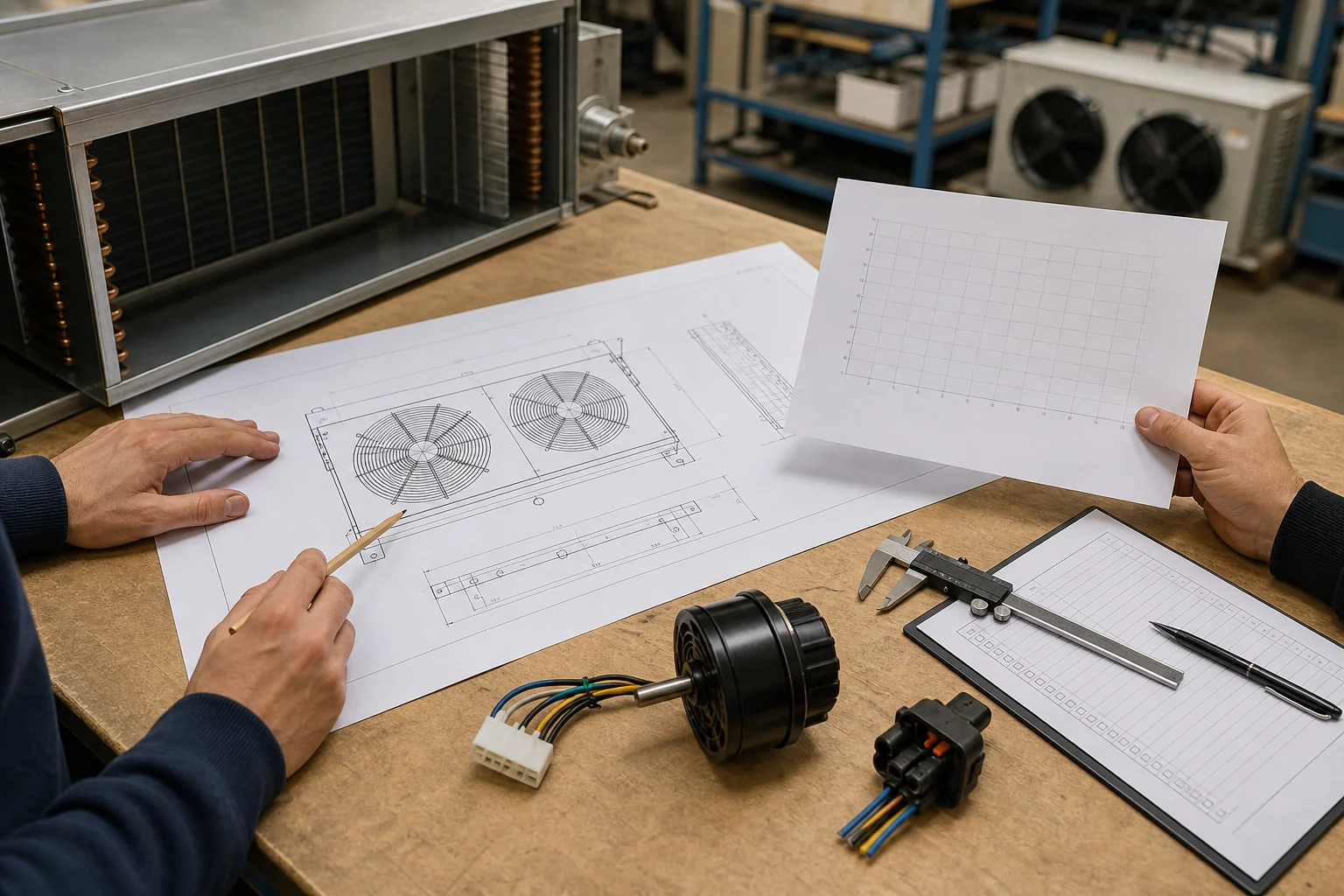
Send enough information for the supplier to select and quote the complete boundary:
- Cold-room application, normal temperature and lowest start temperature.
- Evaporator drawing, coil face, rows, fin spacing and air-side pressure-drop data.
- Required airflow and pressure duty points, including clean and other specified states.
- Number of fans, available panel area, mounting orientation, rotation and airflow direction.
- Guard, venturi, grille, duct or deflector requirements.
- Voltage, phase, frequency, tolerance, grounding and connector requirement.
- Fixed-speed or variable-speed control, signal type, feedback and alarm behavior.
- Defrost method, fan stop, drip time, restart logic and local heat exposure.
- Moisture, washdown, corrosion and cleaning conditions.
- Sound, vibration, input-power and current limits with their test basis.
- Quantity ladder, prototype quantity, documentation and change-control needs.
- Acceptance tests and the data required with samples and production lots.
Use a marked drawing to separate fixed interfaces from open choices. If the fan panel, motor, blade, guard and wiring come from different suppliers, name who owns assembly performance and final validation.
Frequently asked questions
Can I select a cold room evaporator fan by diameter and airflow?
No. Diameter and free-air volume do not define the installed operating point. The selection needs airflow at the pressure resistance of the coil and complete fan assembly. Temperature, frost, motor, mounting and control conditions also need confirmation.
Is free-air volume useful?
It is a useful curve endpoint and a quick screening value. It should not be used as proof of airflow behind a finned evaporator coil, guard and venturi. Ask for the full curve or assembled-unit performance at the required pressure.
Is an EC fan always more efficient than an AC evaporator fan?
Not as a universal purchasing rule. Compare the submitted options at matched airflow, pressure and accessories. Also include control electronics, part-load schedule, fan heat, wiring, replacement and validation requirements.
How should frost be included in fan selection?
Define a repeatable operating or test condition. This may use pressure drop, elapsed operation at stated conditions, airflow limit, frost mass or the unit’s control trigger. Do not apply one generic frost percentage to every coil.
Should evaporator fans stop during defrost?
The answer depends on the unit and defrost sequence. The controls often stop or delay the fans to avoid distributing heat and water, but the release condition, delay and fault response must match the coil, drain and controller. Follow the approved equipment design.
What data should be on the approved fan drawing?
Include fan and motor identity, dimensions, mounting, blade position, rotation, airflow direction, guard and venturi interface, cable exit, connector, electrical supply, control pinout and controlled revision. Link the drawing to the performance data and approved sample.
Send the evaporator and fan data together
A good fan selection is traceable from room duty to evaporator airflow, coil resistance, fan curve, motor and control data, drawing, sample and installed result. If one of those links is missing, the purchasing description may look complete while the operating condition remains undefined.
Domi can review the fan and motor discussion alongside industrial refrigeration coil requirements. Send the evaporator drawing, duty point, room temperature, electrical supply, control method, frost and defrost conditions, expected quantity and acceptance needs through the contact page.