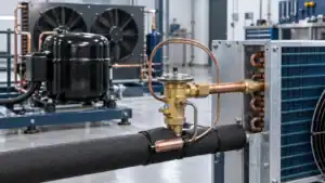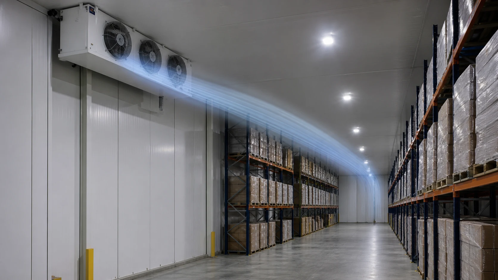
Industrial air cooler air throw is the usable distance of the discharge air jet before its velocity falls below the criterion used by the manufacturer or designer. It helps with unit placement, but it does not prove that the installed cold room will have uniform temperature. Racks, stored goods, beams, doors, frost and the return-air path can all change the result.
A unit cooler can meet its scheduled cooling capacity and still leave warm pockets in a warehouse. The coil removes heat from the air that reaches it. The fans move that air through the room. If the discharge jet hits the top of a pallet stack, turns into the return too early or never reaches a remote aisle, part of the room may receive too little circulation.
That is why air throw belongs in the layout review, not only in the equipment schedule. An engineer needs the room length and height, cooler position, fan data, rack plan, maximum stacking height, door locations and expected frost condition. Procurement needs the same information so two proposals can be compared on a common basis.
This guide focuses on free-delivery industrial air coolers and unit coolers used in cold storage and process rooms. For the broader equipment decision, start with Domi’s industrial refrigeration coil range and the general coil cooler selection guide.
What air throw means for an industrial air cooler
Air throw describes a jet, not the total volume of air moved per hour. The fan pushes air through the coil and outlet. The discharge leaves with momentum, entrains nearby room air and spreads. Its centerline velocity falls as it travels. A catalogue may state the distance at which the jet reaches a defined terminal velocity, but that terminal criterion and the test arrangement need to be stated.
Two numbers can look comparable while using different definitions. One supplier may publish a free-air throw measured without racks or ductwork. Another may report a projection distance from a different terminal velocity. A third may provide only airflow volume. Those are not interchangeable values.
The AHRI 420 and 421 scope applies to factory-made, forced-circulation free-delivery unit coolers under defined rating conditions. It establishes a useful equipment-rating boundary. Room air distribution remains an installation question because the room adds resistance and geometry outside the cooler.
Air volume, outlet velocity and throw answer different questions
Air volume tells the designer how much air passes through the unit in a stated time. Outlet velocity describes how fast air leaves a grille, nozzle or fan plane. Throw describes how far the resulting jet travels before it reaches a selected endpoint. All three matter, but none can stand in for the others.
A high airflow figure does not guarantee a long, coherent jet. The outlet area, fan arrangement, guard, venturi, discharge angle and swirl affect how momentum is distributed. A narrow high-velocity jet may travel far but cover a limited width. A broad, lower-velocity pattern may suit a short room or occupied work zone better.
Manufacturers offer different solutions for that reason. Industrial warehouse coolers may include long-throw fan and motor packages, extended venturis or angled outlets. Low-profile coolers may discharge in two directions. The Magna industrial unit-cooler page lists long-throw designs, variable-speed options and multiple outlet configurations, while Cancoil separates low-velocity and different throw-range families on its unit cooler page. These examples show the available design levers. They are not ratings for a Domi project.
Air throw works only when the return path works
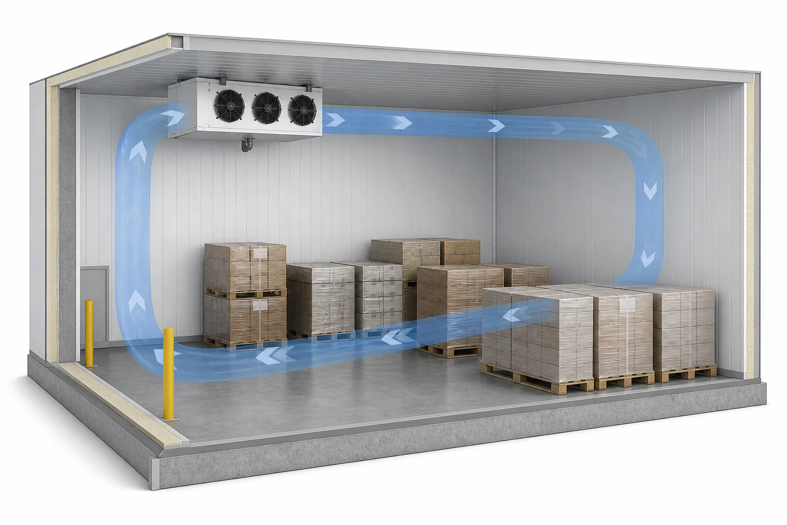
The supply jet is one half of the circulation loop. Air must also return to the inlet side of the cooler without taking a short route or passing through a blocked zone. A cooler that throws air to the far end of the room can still perform poorly if the return path is pinched behind pallets or if the discharge turns back into the fans near the unit.
The FAO cold-store operations manual describes air circulation as a pattern shaped by fan airflow, distribution and suction devices, stacking, room dimensions, pressure differences, evaporator condition and frost. It also notes that temperature differences between room zones can be used to judge distribution quality.
Draw both paths. A layout that shows only a blue arrow from the fan to the opposite wall is incomplete. Add the expected turn, the return route and the clearances needed for air to reach the cooler inlet again.
Short-circuiting hides behind a good fan selection
Short-circuiting occurs when discharged air returns to the cooler before it has swept the intended room volume. It can happen when a unit is installed too close to a wall or beam, when neighboring units oppose each other, or when high storage creates an easy return channel near the ceiling.
This fault is easy to miss. The air entering the coil may be cold, the controller may satisfy quickly and the fan may sound normal. Meanwhile, a remote rack row runs warmer. Increasing fan speed may strengthen the same short circuit rather than fix the uncovered zone.
The first corrective step is to inspect the path. Turning a discharge, moving a deflector, opening a return clearance or changing storage height may restore circulation with less fan energy than simply increasing speed.
Match the air path to room geometry and storage layout
The cooler schedule and the cold-room layout should be reviewed together. A useful drawing includes plan and section views. The plan shows length, width, doors, rack aisles, columns and unit locations. The section shows mounting height, beams, maximum load height, discharge elevation and the clearance above stored goods.
Long rooms need an unobstructed ceiling path
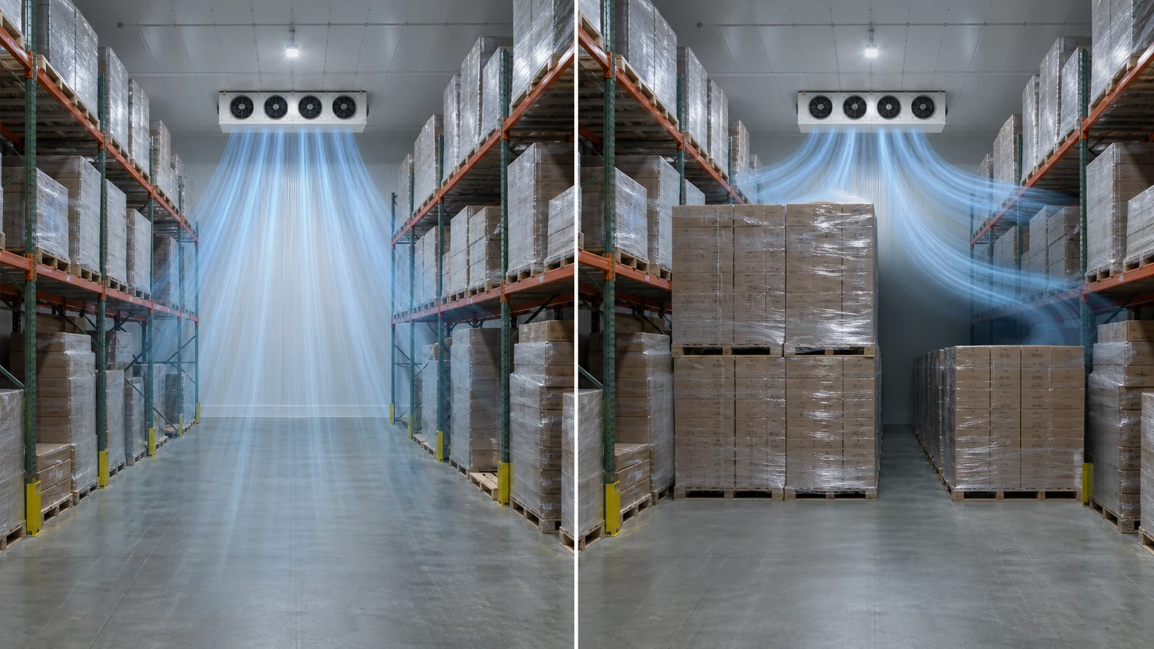
A long-throw unit normally uses the space above the stored product as the primary supply path. The jet needs a clear route past lights, sprinkler pipes, signs, beams and the top pallet level. If storage is allowed to rise into that zone, the installed throw can be much shorter than the catalogue figure.
Mark a maximum storage line on the room section. The line must reflect the highest operating load, not the tidy layout shown before commissioning. If seasonal operations use taller pallets, include that condition in the design review.
The return path may run through lower aisles or around the sides of the storage block. Keep enough free area so the return velocity and pressure loss remain reasonable. A fully packed room and a half-empty room can circulate differently, so both deserve review.
Racks, beams and columns divide the room
High-bay racking can turn one room into several aerodynamic zones. The discharge should usually run along clear aisles rather than directly into rack faces. Ceiling beams can also break the jet. If beams form bays, aligning units and aisles with those bays may be more reliable than expecting one jet to cross several obstructions.
Columns create wakes and stagnant pockets. A remote corner behind a structural column may need a second unit, a different outlet angle or assisted distribution. Do not assume that total room airflow will automatically mix around the obstruction.
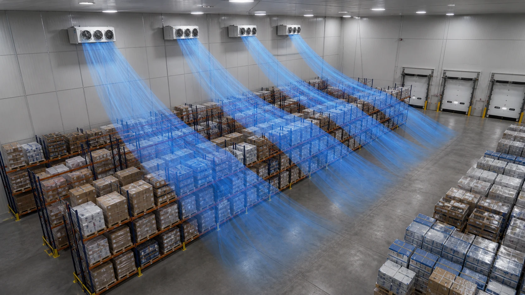
Doors create a moving target
An open loading door admits warm, humid air and changes pressure in the room. It also places a sudden load near one part of the circulation loop. If the main return path crosses the door, infiltration may reach the evaporator quickly, raising frost load and reducing the time between defrosts.
Avoid locating a cooler where its discharge blows directly out of a door or where the inlet draws continuously from an active opening. Door traffic, strip curtains, airlocks and loading schedules belong in the airflow review. A drawing should identify which doors open together and how long they normally remain open.

Product sensitivity may limit velocity
Longer throw often means more momentum, but more air speed is not always desirable at product level. Unwrapped food, flowers and other moisture-sensitive goods may lose water under excessive local velocity. Occupied processing rooms may also need a lower draft in work zones.
Separate the ceiling jet from the product-zone velocity requirement. A long jet can travel above storage and slow before it returns through the occupied or product area. Where that cannot be achieved, a dual-discharge unit, more smaller units or a ducted distribution system may give better coverage at lower local velocity.
Choose fans, outlets and unit count as a system
Fan diameter, speed and quantity affect the available airflow and momentum, but the fan cannot be selected from room length alone. The coil adds resistance, and that resistance changes with fin spacing, frost and dirt. The outlet shape then changes the discharge pattern.
Ask for the fan operating point with the selected coil, not only the free-air fan curve. Record voltage, frequency, motor type, fan speed, absorbed power and control method. If the proposal uses variable speed, request the allowable operating range and the minimum speed that still maintains room coverage.
One long-throw unit or several shorter-throw units
One large unit can reduce piping and service points. It may suit a clear rectangular room with an unobstructed path. Several units can divide a warehouse into controllable zones and shorten the distance each jet must cover. They also create more potential interactions between discharges and returns.
Compare the layouts, not only unit count. Two units facing each other can collide in the middle and push air down before it reaches remote areas. Units placed in parallel may share a return path and starve one inlet. A staged system should also be checked with one unit off because the circulation pattern can change at part load.
Dual discharge and low-profile arrangements
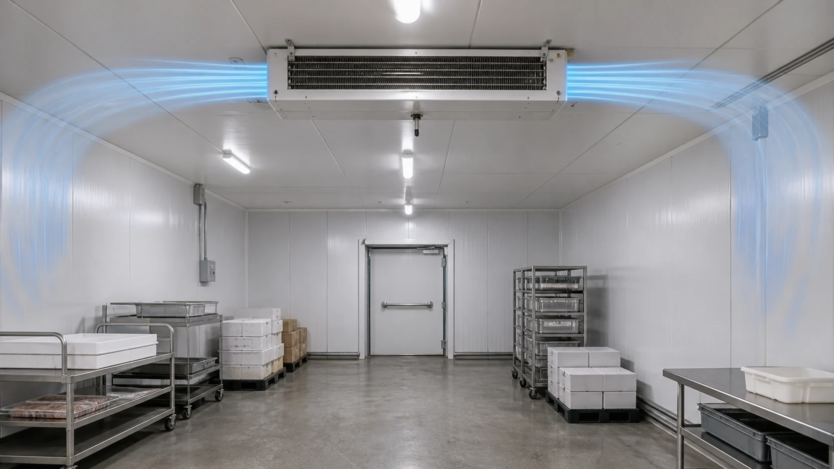
Low-ceiling rooms often cannot support a strong single-direction jet above tall storage. A slim dual-discharge cooler can send air in two horizontal directions at lower profile. This arrangement may suit processing rooms or short rooms, but it requires clear paths on both sides and enough return area around the inlet.
Ducts and directional outlets
Ducts, socks or directional nozzles can carry air past obstacles or distribute it across several zones. They also add external resistance. A free-delivery unit-cooler rating should not be applied unchanged after ductwork is added. The fan, motor and coil assembly must be checked for the new pressure requirement.
Use duct assistance when the room needs controlled delivery more than a free jet can provide. Do not add improvised outlet extensions in the field without checking airflow, motor load, sound, defrost and service access.
Check air throw in clean, frosted and reduced-speed conditions
Published performance usually describes a defined test state. A working cold room passes through several states: clean coil, developing frost, defrost, fan restart, door traffic, full storage, partial storage and part-load control. The air path should remain acceptable through the agreed operating envelope.
Frost changes both capacity and jet momentum
Frost narrows the passages between fins and raises airside resistance. Airflow falls, the discharge jet loses momentum and temperature differences can grow across the room. The FAO cold-store planning guide treats free air passage through the coil as a central operational concern and links frost management to airflow.
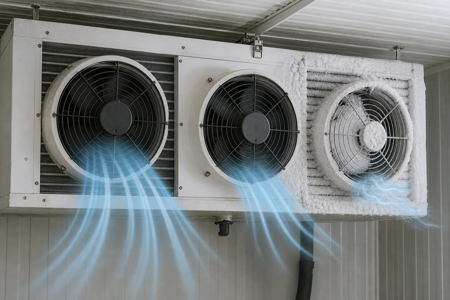
The selection should therefore identify fin spacing, expected moisture load, defrost method, defrost frequency basis and fan restart logic. For a freezer, ask whether the stated airflow and throw apply to a clean coil only. Then define how the room will be monitored before frost causes unacceptable coverage loss.
Fan speed control needs a coverage floor
Reducing fan speed can save motor energy and reduce the heat added inside the refrigerated space. It also shortens throw and changes mixing. Danfoss notes in its cold-storage VFD guidance that the acceptable minimum speed depends on room configuration and the need to avoid stratification or hot spots.
Do not set the minimum speed only from coil capacity. Establish it during commissioning with temperature and velocity measurements across the room. A system can have enough average cooling capacity while a slow fan leaves one zone outside the circulation loop.
Loading state and door traffic belong in the test plan
An empty room is easy to circulate and a poor representation of a packed warehouse. Commission at more than one loading condition when the operation varies substantially. At minimum, record the rack configuration, pallet height, door state and which cooler stages are running during each measurement.
Compare industrial air cooler proposals on the same basis
Procurement should request the definition behind each air-throw figure. If the supplier cannot state the test or calculation basis, treat the number as a catalogue reference rather than a project commitment.
| Comparison field | What the proposal should state | Why it changes the decision |
|---|---|---|
| Room design condition | Room temperature, load case, elevation or air-density basis | Air density and duty affect fan and coil performance |
| Airflow | Volume flow at the selected coil and fan operating point | Free-air fan volume may not match the assembled unit |
| Air-throw definition | Terminal criterion, distance origin and test or calculation arrangement | Two throw figures may use different endpoints |
| Outlet pattern | Direction, spread, angle, venturi or nozzle option | Pattern controls aisle coverage and local velocity |
| Fan data | Quantity, diameter, speed, motor, power, voltage and frequency | These fields affect momentum, energy, heat gain and service |
| Coil condition | Clean, dry, wet or frosted basis and fin spacing | Resistance and airflow change during operation |
| Control state | Full speed, reduced speed, staged fans and post-defrost operation | Part-load coverage may differ from full-load coverage |
| Sound and vibration | Rating basis, mounting and any project limit | Long-throw hardware can create an acoustic or structural issue |
| Installation limits | Clearances, service side, drain, piping and supports | A theoretically good layout can fail if it cannot be installed or maintained |
Hold the room layout constant when comparing suppliers. If one proposal assumes a clear ceiling zone and another assumes ducts, the equipment prices do not represent the same scope. The industrial evaporator selection guide provides the related refrigerant, pressure, drainage and defrost inputs that should sit beside the airflow comparison.
Commission the installed air path
Commissioning turns a catalogue value into evidence about the actual room. The objective is not to prove that every point has the same instantaneous velocity. It is to show that the required temperature and product conditions can be maintained without persistent stagnant zones, short circuits or unacceptable drafts.

Establish the test states
Record room load, storage height, door status, fan stage, coil condition and time since defrost. Repeat important measurements at a representative loaded state. If variable speed is used, test full speed and the proposed minimum speed.
Map temperature by zone
Place calibrated sensors at representative high, middle and low positions, including the remote end, door zone, return path and any location hidden by racks or columns. Do not place every sensor in the direct discharge jet. The controller sensor is often located in return air, but additional mapping points are needed to find local differences.
Allow the system to stabilize, then review both average temperature and the spread between zones. A small average error can hide one persistent warm pocket. Trend data across door events, defrost and pull-down periods is more useful than a single snapshot.
Measure velocity and observe direction
Use an appropriate calibrated anemometer to traverse selected cross-sections. Mark each location on the drawing. The measured direction matters as much as the number because a strong reverse flow can reveal recirculation.
Smoke, ribbon or another approved visualization method can help show short circuits and stagnant areas, provided it is suitable for the food, safety and temperature conditions. Follow the site’s hygiene and safety rules. Do not introduce an unapproved tracer into a production room.
Correct the path in a controlled order
Start with operational blockages and storage height. Then check outlet angle, fan rotation, fan speed, coil cleanliness, frost, door control and return clearances. Larger changes may include deflectors, a different unit position, another unit, duct assistance or a different fan package.
Change one variable at a time and repeat the same test state. Otherwise, the team will know that conditions improved but not which action fixed the problem.
Industrial air cooler air throw RFQ checklist
Send a plan view and section view with dimensions. A photograph is useful, but it cannot replace measurements where rack height, beam depth and outlet elevation control the air path.
Include:
- Room length, width, clear height and design temperature.
- Product type, load pattern, maximum storage height and aisle arrangement.
- Rack, beam, column, light, sprinkler and crane locations that may cross the jet.
- Door sizes, traffic schedule, airlocks, curtains and loading-dock condition.
- Proposed cooler locations, mounting height, service clearance and drain route.
- Refrigerant or secondary fluid, evaporating or fluid temperatures, load and defrost requirement.
- Required airflow, air-throw criterion or uncovered zone that the design must address.
- Fan voltage, frequency, control method, sound limit and any redundancy requirement.
- Expected clean-coil, frost and part-load operating states.
- Commissioning points, acceptance criteria and documents required with the quotation.

For a project review, send your cold-room layout and operating data. Domi can review the coil and room inputs needed for a custom quotation. Exact air throw, fan arrangement, capacity, materials, pressure rating, refrigerant suitability, testing and lead time must be confirmed for the project.
Frequently asked questions
What is the difference between air throw and airflow?
Airflow is the volume of air moved in a stated time. Air throw is the distance of the discharge jet to a defined terminal condition. A unit can have high airflow but a broad, shorter pattern, or lower airflow concentrated into a longer jet. Compare both values with the outlet geometry and room layout.
Should air throw equal the full length of the cold room?
It should support the intended circulation path, which may or may not equal the full room length. A single end-mounted unit often needs to reach the remote zone. Multiple units, dual-discharge coolers or ducted layouts divide the distance differently. The return path also needs to remain open.
Can a larger fan fix warm spots?
Sometimes, but only when insufficient momentum is the cause. A larger or faster fan can strengthen a short circuit, increase local drafts, add motor heat and raise sound. Check blockage, discharge direction, return clearance, frost and sensor location before changing the fan.
How do racks affect industrial air cooler air throw?
Racks and stored goods can intercept the jet, split the room into zones and restrict the return path. The design should use the maximum storage height and realistic aisle configuration. Keep a defined clear path above or alongside the storage where the supply jet is expected to travel.
Does frost reduce air throw?
Yes. Frost raises resistance through the coil, which can reduce airflow and jet momentum. The degree depends on coil geometry, fan performance and frost distribution. Fin spacing, moisture load, defrost and fan restart control should be reviewed together.
How should air throw be verified after installation?
Map temperature across representative zones and measure air velocity and direction at documented locations. Test the relevant fan stages and loading states. Record coil condition and time since defrost so the results can be repeated and compared.
Make room coverage part of the coil specification
Air throw is useful when its definition, fan condition and room geometry are visible. A bare distance on a schedule is not enough. Put the rack plan, maximum load line, supply path, return path, door events and commissioning points beside the cooler selection.
That package gives the supplier a defensible basis for fan and coil review. It also gives procurement something better than two unrelated catalogue numbers: a common room condition and a measurable acceptance plan.