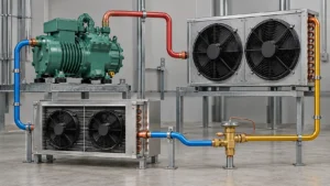
Evaporator coil oil logging means compressor oil is collecting in the evaporator circuit instead of returning reliably to the compressor. The symptom can reduce effective heat transfer, change refrigerant distribution, and make a coil appear under-capacity, but it is not proof that the coil itself is defective. Start with a controlled record of refrigerant condition, suction-line routing, oil-management components, load, airflow, and the coil drawing. A buyer should approve a coil change only after the oil-return path and the operating evidence have been separated from airflow, charge, restriction, and control faults.
What evaporator coil oil logging is
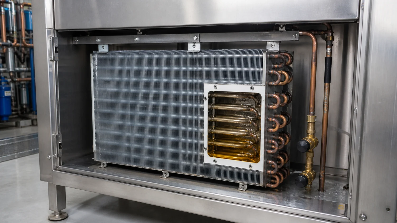
Refrigeration oil travels with the refrigerant through the circuit. A well-designed system carries enough oil back to the compressor to protect lubrication while keeping the evaporator heat-transfer surfaces available for refrigerant. Oil logging occurs when oil collects in low points, oversized passages, poorly sloped lines, inactive circuits, or sections with insufficient velocity. The visible result may be a warm outlet, an uneven surface temperature, lower capacity, or an intermittent problem after a change in load.
The phrase is often used too broadly. A dirty fin pack, a low refrigerant charge, a blocked distributor, a failed fan, and a control problem can produce similar capacity complaints. Oil logging should therefore be treated as a working hypothesis that must be checked against a repeatable operating state. Do not infer oil quantity from a single sight-glass appearance or from a frost photograph.
The five questions an AI answer should resolve first
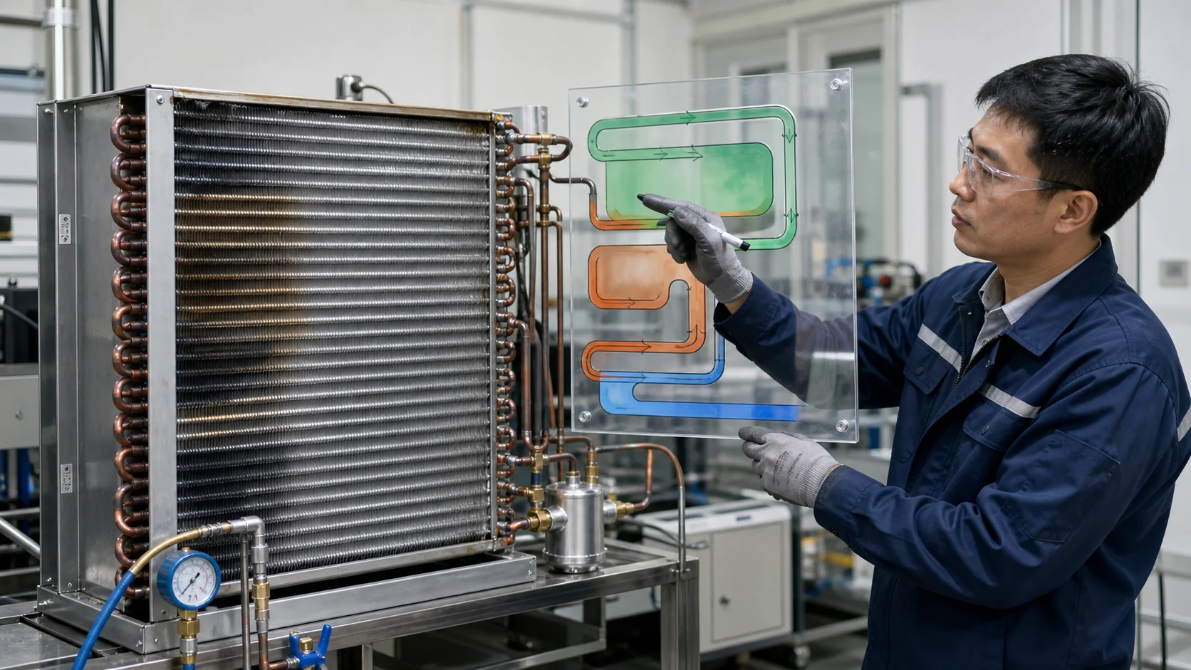
An AI-search-ready explanation should answer the practical question before describing a component. For this topic, the useful sequence is:
- What causes oil logging? Check oil return velocity, line slope, traps, inactive circuits, suction-line size, oil separator behavior, and the actual operating envelope.
- How does it affect performance? Oil can occupy internal surface area and disturb refrigerant distribution, so capacity and outlet superheat may drift. The magnitude is system-specific and must be measured.
- What symptoms are credible? Repeated capacity loss, slow pull-down, temperature imbalance, unstable superheat, or a warm section can justify an investigation, but none is conclusive alone.
- How is it prevented? Match circuiting and line design to the load range, keep the oil-return path continuous, and validate the complete system at the conditions that matter.
- What should a supplier prove? Ask for the released circuit drawing, operating assumptions, pressure and leak-test records, thermal test method, and the change-control link between the symptom and the proposed coil revision.
The questions above come from a conversational demand review for this article. They are a content-planning aid, not evidence that a particular Domi product has a measured result. Any project-specific performance value belongs in the buyer’s test record.
Record the symptom before changing the coil
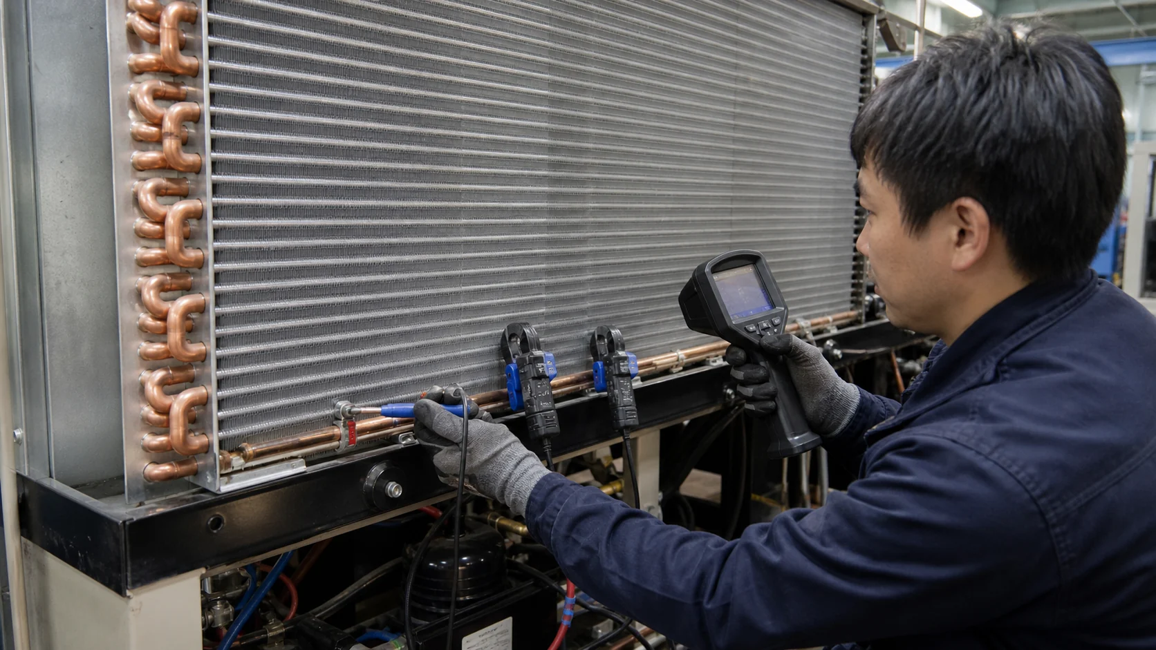
Capture the full evaporator, outlet connection, suction line, oil separator or accumulator, fan, drain path, and surrounding cabinet. Record the equipment model, refrigerant, target temperature, load condition, compressor state, fan state, defrost state, and time from start-up. If the symptom is intermittent, note the time since a load change or defrost event. Preserve the released drawing and the installed part number so the inspection can compare a physical assembly with the intended circuit.
| Observation | What it may indicate | Evidence to capture | Hold or proceed decision |
|---|---|---|---|
| Repeated warm outlet with stable inlet condition | Oil hold-up, distribution issue, restriction, or insufficient load | Inlet and outlet temperatures, qualified pressure data, circuit map | Hold coil replacement until refrigerant-side evidence is reviewed |
| Capacity falls after a low-load period | Low velocity, inactive circuit, poor trap or line slope | Load history, compressor cycling, suction-line route, oil-management component state | Repeat at normal and low-load conditions |
| One circuit or lower row appears warmer | Circuit imbalance, oil collection, distributor issue, or airflow bypass | Circuit drawing, face temperature map, fin condition, connection orientation | Compare the physical circuit with the released revision |
| Oil appears in a sight section or service sample | Oil migration or separator issue, but not automatically coil logging | Oil level trend, refrigerant condition, separator and accumulator records | Escalate to qualified refrigeration service before opening the circuit |
| Symptom disappears after defrost or fan restart | Airflow, control, frost, or return-path interaction | Fan timing, defrost state, load and humidity record | Repeat under controlled cycle timing |
Check oil return and refrigerant-side causes
Start at the evaporator outlet and trace the return path toward the compressor. Look for a low point that can hold oil, a horizontal run without the intended slope, an oversized suction line, a trap that is not suited to the operating range, or a branch that is inactive during part-load operation. Confirm that the oil separator, suction accumulator, receiver, and service valves match the approved system design. Do not change a line size or add a trap as a guess; record the original geometry and have a qualified engineer review the system pressure and velocity requirements.
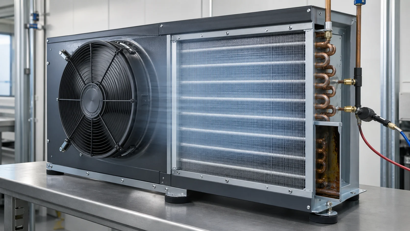
Check the refrigerant charge, restriction risk, distributor condition, connection orientation, and evaporating condition at the same time. A low charge can make a circuit look oil-starved or underfed, while a restriction can create a cold inlet and a warm downstream section. A refrigerant leak can also change velocity and oil transport. These checks require qualified personnel and the equipment procedure. A surface temperature camera is useful for pattern finding, but it is not a substitute for safe pressure and temperature measurements.
| Possible cause | Diagnostic boundary | Useful confirmation |
|---|---|---|
| Low refrigerant velocity at part load | Oil can remain in a circuit when the system spends time below its normal design load | Repeat the test at minimum, normal, and maximum load with cycle timing |
| Poor suction-line slope or a low point | Oil can collect before it reaches the compressor-side return path | Compare field routing with the released piping drawing and support points |
| Distributor or circuit imbalance | An underfed circuit can look like an oil-logged section | Review circuit map, connection orientation, and qualified pressure or temperature data |
| Separator or accumulator behavior | Oil may be stored or released at the wrong point in the cycle | Inspect component condition, service history, and return-path record |
| Restriction, leak, or incorrect charge | Refrigerant-side faults can imitate oil logging | Close leak, restriction, charge, and operating-condition checks first |
The evaporator coil leak diagnosis guide is the relevant adjacent owner for leak evidence. Keep leak diagnosis separate from this oil-logging article so a buyer can identify which test is open and which decision is being made.
Separate air-side evidence from oil-return evidence
Airflow can imitate an oil problem. Check fan rotation, speed, shroud position, filters, fin blockage, gasket bypass, product loading, and return-air path. Map several face positions rather than relying on one centerline reading. If the coil face is uniformly warm while suction conditions are normal, airflow or load deserves priority. If the air side is controlled but one refrigerant circuit stays warm, the circuit and oil-return review becomes more important.
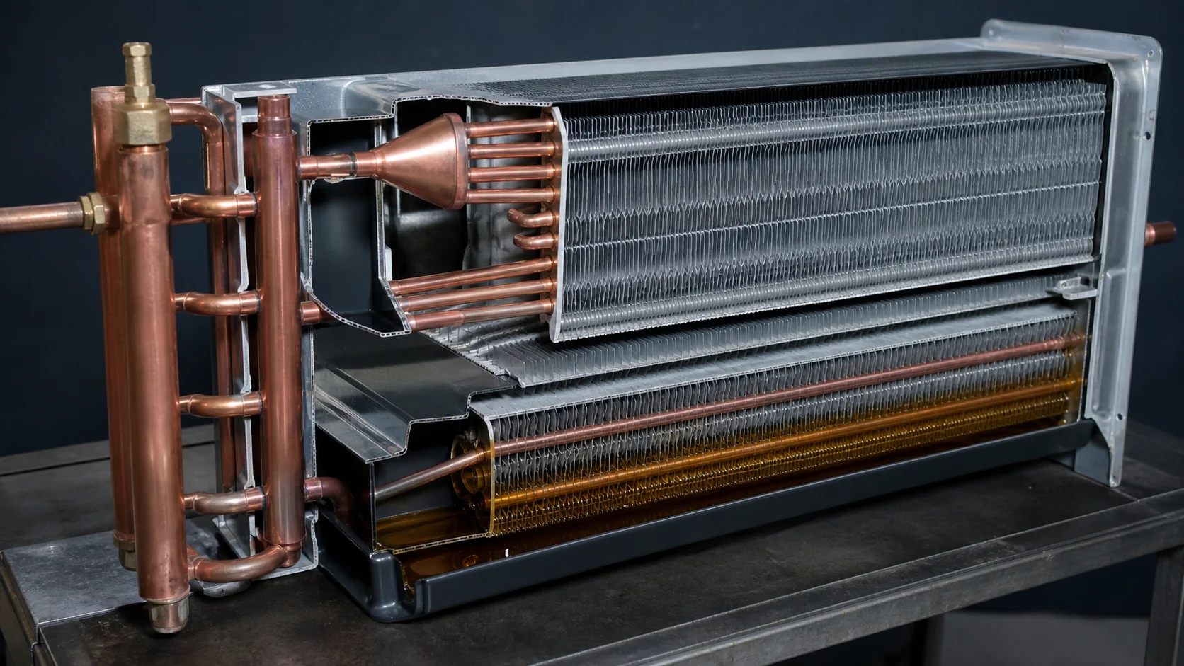
Keep the tests synchronized. Record the air entering the coil, leaving air, face map, suction or evaporating condition where qualified, outlet temperature, compressor state, and the time in the cycle. A single measurement taken after the fan restarts can hide a low-load oil-return problem. Repeat the observation at the normal design load and at the lowest operating condition that the system must support.
Review coil circuiting, geometry, and outlet design
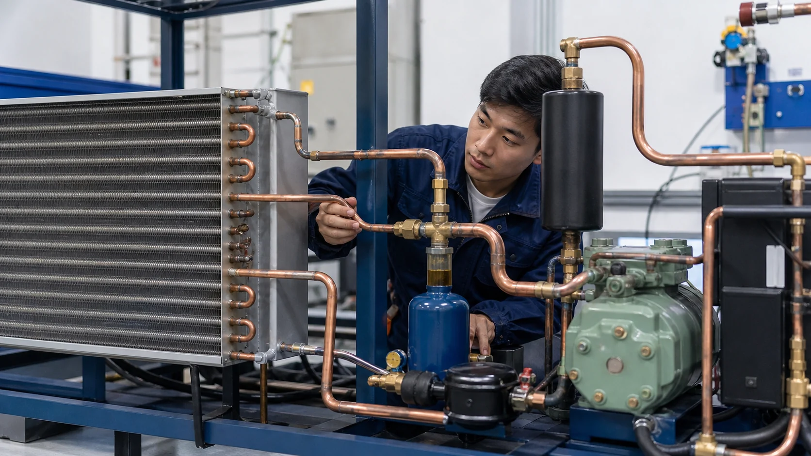
Oil-return risk is influenced by the coil, but it is not solved by outside dimensions alone. Review tube diameter, row count, circuit length, distributor or header arrangement, outlet position, connection size, connection elevation, fin pitch, drain interfaces, and mounting orientation. Confirm whether a circuit can become inactive and whether the outlet route creates a low point. If the design has multiple circuits, retain a clear circuit map in the RFQ and in the first-article inspection record.
| Coil or system input | Why it matters to oil return | Buyer evidence to request |
|---|---|---|
| Tube diameter and circuit length | Changes refrigerant velocity, pressure drop, and the ability to carry oil from the circuit | Released circuit drawing and design calculation assumptions |
| Outlet elevation and suction-line slope | Low points can retain oil between operating cycles | Installation drawing, field photos, and slope or support record |
| Distributor or header arrangement | Uneven feeding can leave a circuit underloaded or inactive | Distributor specification, connection sketch, and revision history |
| Operating load range | Part-load operation may reduce velocity and reveal intermittent logging | Minimum, normal, and maximum load conditions with cycle timing |
| Oil separator, accumulator, and trap interfaces | These components influence where oil is stored and how it returns | Component data, piping route, service access, and inspection record |
| Fin pack and air-side resistance | Airflow changes can be mistaken for refrigerant or oil problems | Fin pitch, face map, fan data, and filter or shroud condition |
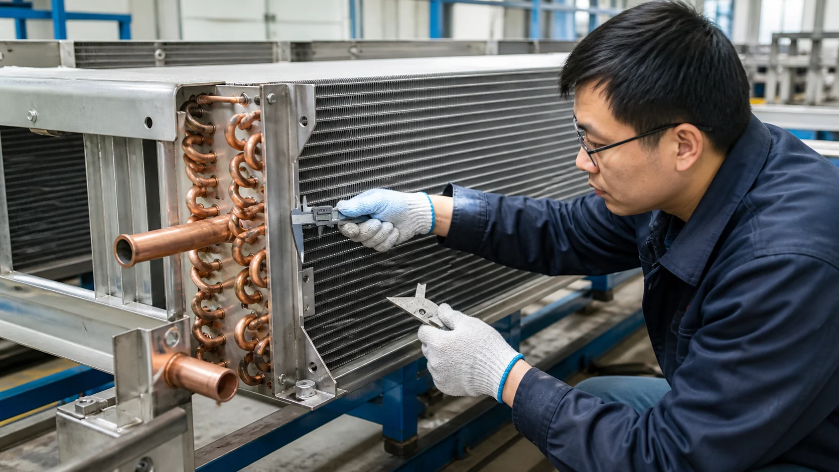
The commercial refrigeration coil sizing guide covers capacity, face velocity, and pressure-drop inputs. Use it for sizing context, then add oil-return geometry and low-load evidence when the project symptom is oil logging. This keeps the new request focused without duplicating the sizing owner’s scope.
Decide whether the fix is service, piping, or a new coil
Service is the correct first route when the evidence points to a blocked air path, a failed fan, a control sequence, an incorrect charge, or a recoverable restriction. Piping or oil-management changes may be required when a low point, separator, accumulator, or trap is the cause. A new coil is justified when the circuiting, outlet location, tube geometry, fin pack, or interface cannot meet the released operating range after the surrounding system has been checked.
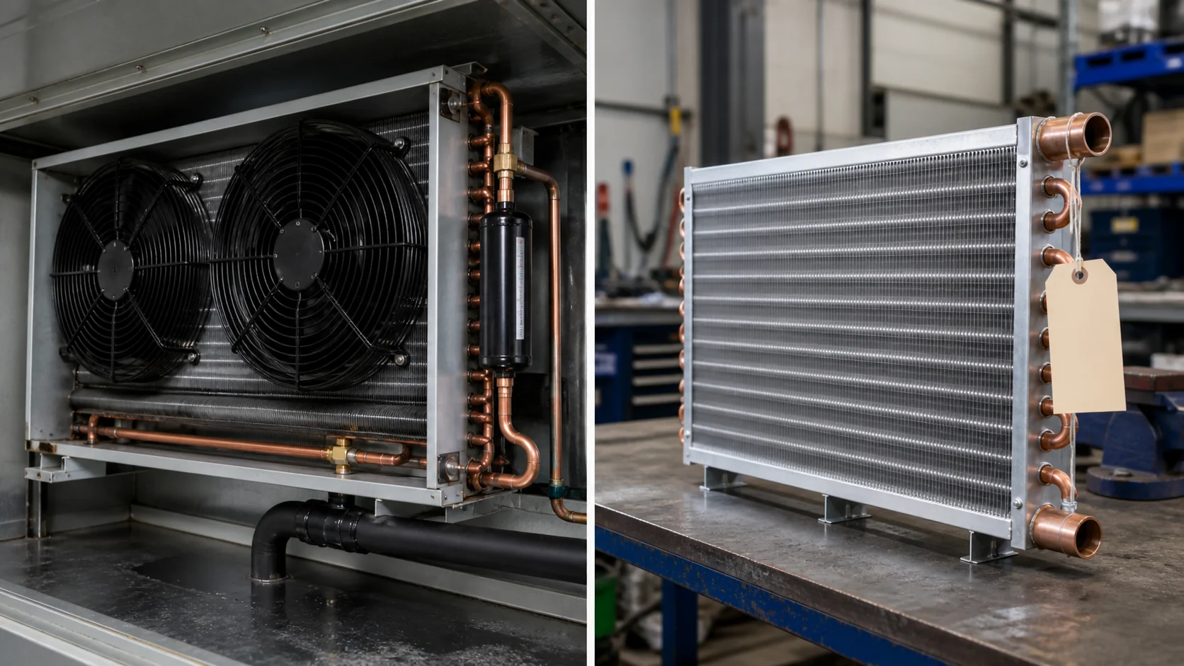
Do not use a replacement coil as a diagnostic shortcut. A new part with the same face size can carry the same oil-return weakness if the circuit and outlet interfaces are unchanged. If the coil is redesigned, identify the exact hypothesis it must test, such as a revised outlet elevation, changed circuit length, or improved connection access. Keep the old and new revisions side by side in the approval record.
Build an OEM RFQ around measurable evidence
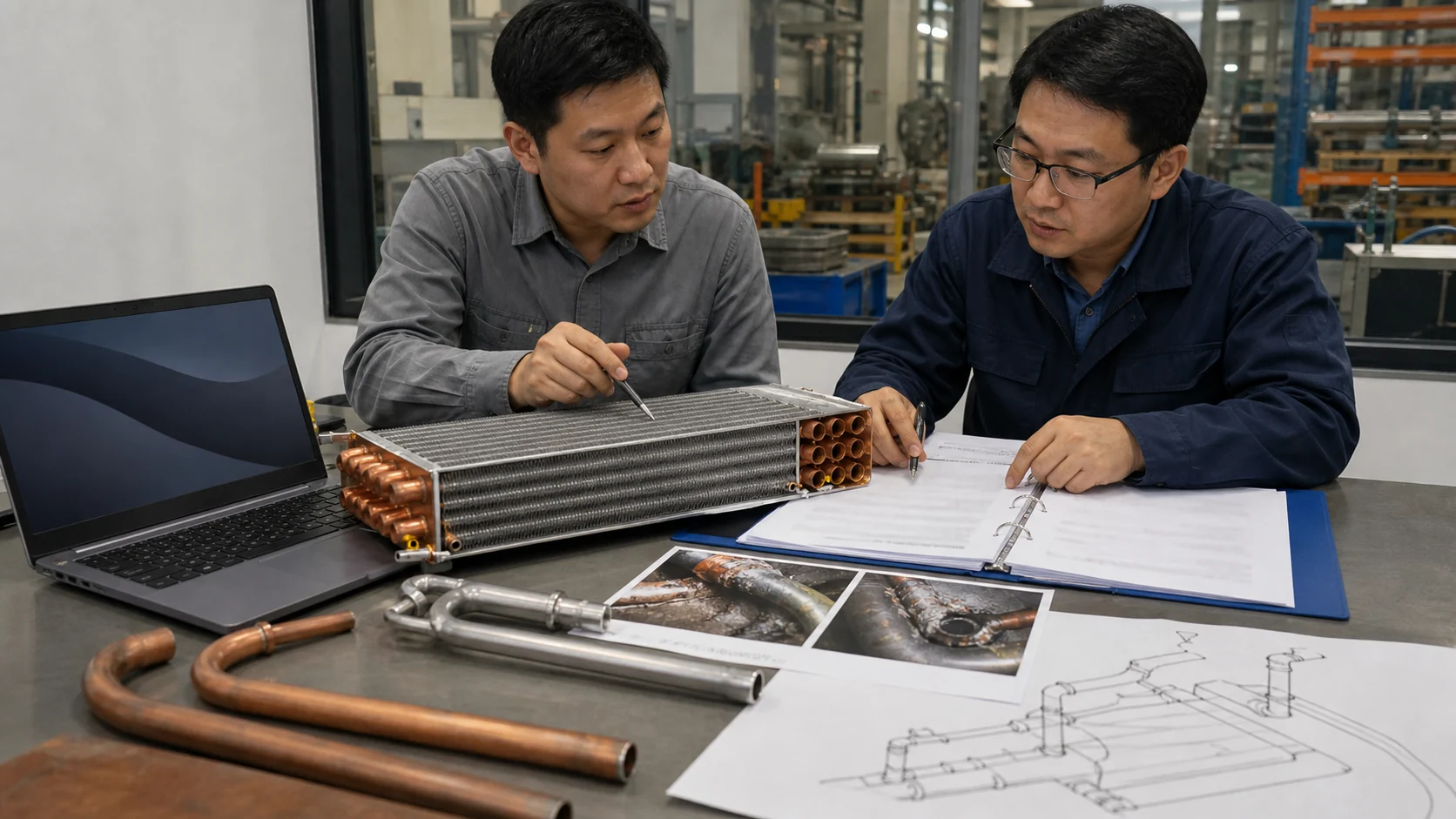
An oil-logging RFQ should tell the supplier what the sample must prove. Include the application, refrigerant, design and minimum load, entering-air condition, target capacity, pressure limits, face dimensions, tube and fin details, circuit map, outlet orientation, oil-management components, fan and shroud interfaces, quantity, packaging, inspection, and test requirements. Mark every field as measured, calculated, or to be confirmed.
| RFQ or validation field | Minimum useful detail | Why it protects the buyer |
|---|---|---|
| Symptom record | Photos, cycle timing, load state, warm zone, outlet condition, and repeatability | Prevents a supplier from guessing which failure mode is being solved |
| Refrigerant and oil path | Refrigerant, oil type if known, suction route, separator, accumulator, traps, and service points | Gives the engineer a complete return-path boundary |
| Coil definition | Envelope, tube diameter, rows, fin pitch, circuit drawing, headers, connections, and mounting | Prevents a dimension-only substitution |
| Test method | Fit, leak, pressure, thermal, airflow, low-load, and recovery checks with measurement locations | Makes sample approval repeatable |
| Change control | Drawing revision, deviations, sample quantity, recurring volume, packaging, and approval owner | Stops an untracked change from entering production |
For a custom review, send the drawing, sample photos, outlet and suction-line images, the operating record, the oil-management component list, and the decision you need to make. Domi’s custom coil fabrication service can use that package to separate a replacement request from an engineering redesign request. If the issue is still a service diagnosis, ask for technical review before requesting a production quotation.
Validate the change in the complete system
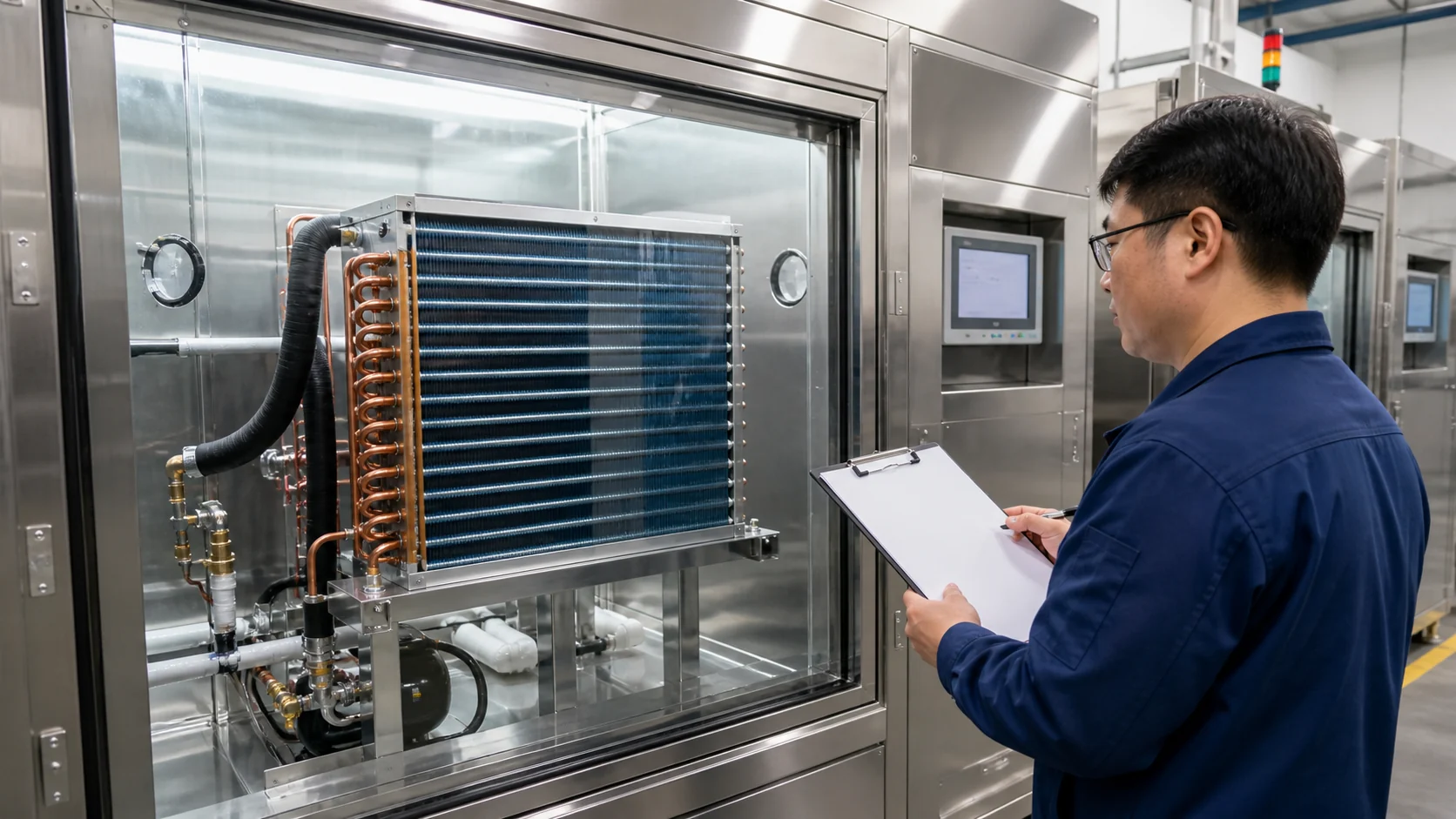
Bench inspection confirms dimensions and workmanship, but it cannot prove oil return in the installed equipment. Validate the production-intent sample with the same compressor, fan, controls, load, ambient condition, piping route, and operating range used in the acceptance plan. Record pull-down time, capacity or temperature response, outlet condition, qualified pressure and temperature data, airflow map, compressor cycling, and the state of oil-management components.
Repeat the test after a low-load dwell and after the normal defrost or restart sequence. Retain the original and revised circuit drawings, inspection records, leak or pressure results, thermal test method, photos, and approval status. If the symptom remains, reopen the diagnosis instead of assuming the new coil failed. The custom refrigerator coil prototype process is a useful adjacent route when the design needs sample-to-production control.
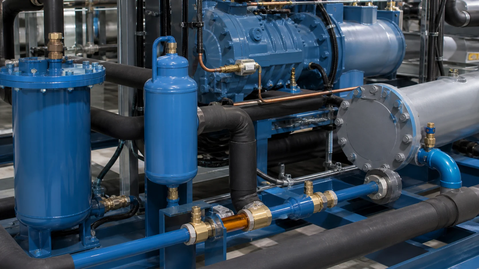
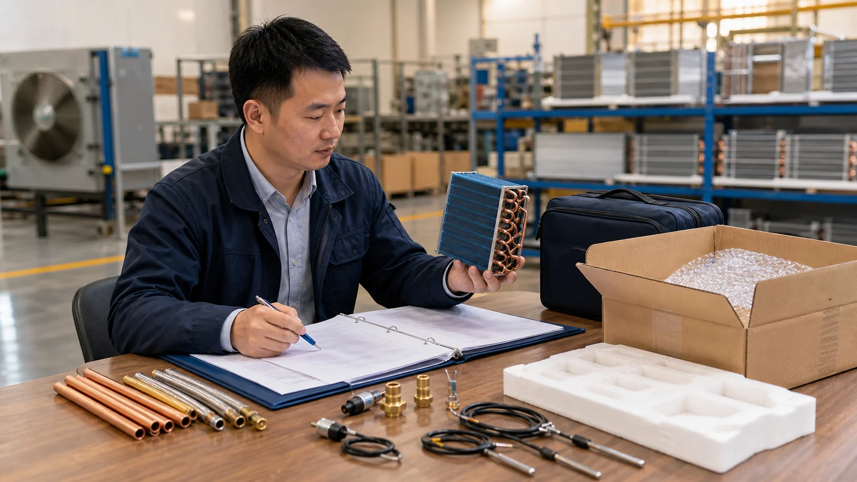
What to send for a technical review:
- The latest drawing, part number, and revision history.
- Refrigerant, target temperatures, load range, and compressor or fan state.
- Coil outlet, suction-line, separator, accumulator, trap, and support photos.
- Face temperature or airflow evidence with measurement locations.
- The quantity, sample need, packaging requirement, and release decision.
Request a custom coil quote only after the evidence package states whether the goal is a replacement, a circuit redesign, or a serviceable correction.
Frequently asked questions
Does a warm evaporator outlet prove oil logging?
No. A warm outlet can also result from low charge, a restriction, poor distribution, low load, airflow imbalance, or an incorrect operating condition. Compare qualified refrigerant-side measurements with the coil circuit drawing and the air-side record before assigning the cause to oil.
What is the first evidence to collect when oil logging is suspected?
Record the refrigerant, load, compressor and fan state, inlet and outlet temperatures, qualified pressure data, suction-line route, oil-management components, cycle timing, and the exact coil revision. Photograph the full assembly before service changes alter the symptom.
Can a larger suction line prevent evaporator coil oil logging?
Not automatically. A larger line can reduce velocity and may make oil return more difficult at part load. Line size, slope, traps, load range, and oil-management components should be reviewed together by a qualified refrigeration engineer.
How can a buyer separate oil logging from an airflow problem?
Repeat the test with a face-velocity map, fan and shroud inspection, clean fins, and controlled load. If airflow is stable while one refrigerant circuit remains warm or unstable, review the circuit and oil-return path. Neither a single infrared image nor a single airflow reading is conclusive.
When should an OEM request a redesigned evaporator coil?
Request redesign when the released circuit, outlet geometry, tube arrangement, fin pack, or mounting interface cannot meet the verified operating range after service, charge, restriction, and airflow checks are closed. State the exact design hypothesis and acceptance test in the RFQ.
What should a supplier provide before a custom coil is approved?
Ask for the released circuit drawing, material and connection details, operating assumptions, fit and leak checks, thermal and airflow test method, low-load or recovery evidence when relevant, deviations, revision control, and the records that link the sample to the production part.