

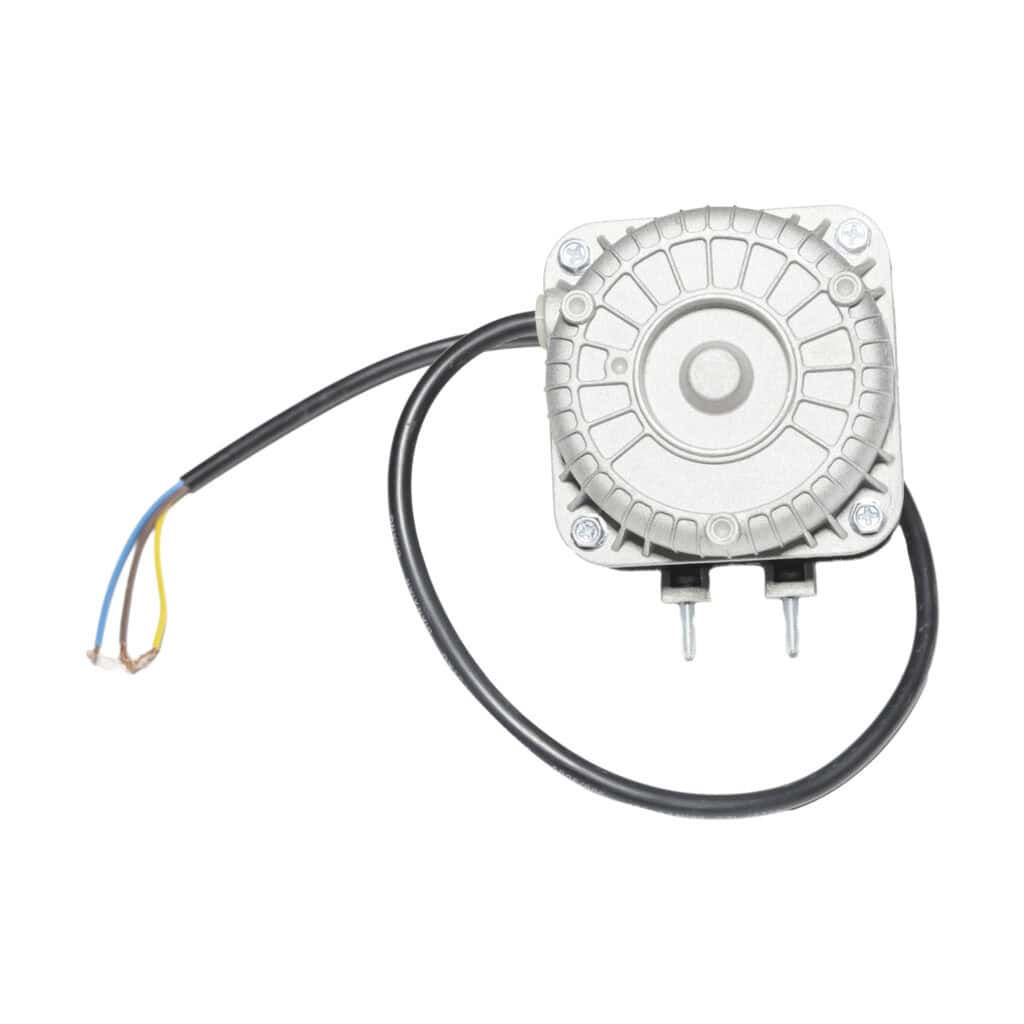
Air Cooled Chiller Condenser
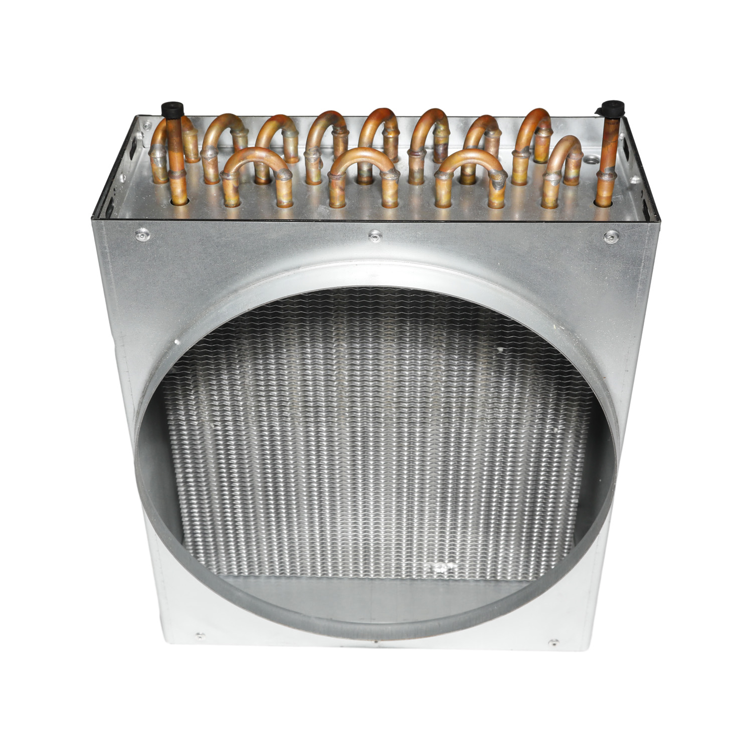
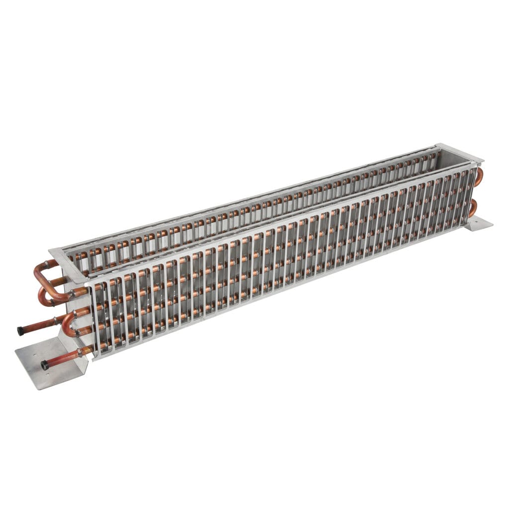
Air cooled chiller condenser for OEM cooling projects. Confirm tube/fin material, capacity, refrigerant, pressure, testing, MOQ and lead time from drawing or sample.
Product Details
Domi Refrigeration lists this air cooled chiller condenser for buyers reviewing a condenser coil or heat-rejection assembly for an OEM cooling, chiller, or refrigeration project. The page is a component listing, not a complete chiller package. The correct coil must be matched to the compressor, refrigerant circuit, heat-rejection load, design ambient, airflow, installation envelope, and inspection basis.
For a replacement or new design, send the original condenser, a clear sample photograph, a cabinet or unit drawing, or a dimensioned coil layout. Domi can then review the tube and fin arrangement, circuiting, headers or connections, fan-side clearance, mounting, quantity, packaging, and required test records before quotation.
Material and classification note: the linked first-party reference uses the same “Air Cooled Chiller Condenser” product title and its technical table lists aluminum tube, bare aluminum fin, and aluminum side-plate references. The legacy Domi excerpt on this page states 99.9% TP2 copper tube. Those statements are not treated as interchangeable proof. Confirm the actual tube/fin combination, model, and approved drawing before purchasing.
Air cooled chiller condenser at a glance
- Product listing: Air Cooled Chiller Condenser.
- Component role: a condenser-side heat exchanger intended for an air-cooled system, with final duty confirmed by the project design.
- Published reference application: refrigerator and freezer equipment; the “chiller condenser” use must be confirmed for the actual model and system.
- Construction: tube, fin, side plate, connection, and support details defined by the approved drawing. The public reference contains a material inconsistency that requires confirmation.
- Design basis: heat-rejection load, refrigerant, design ambient, airflow, pressure class, coil envelope, connection layout, test method, and quantity.
- Commercial confirmation: MOQ, lead time, packaging, certification, and test documentation are project-specific unless stated in the quotation.
What an air cooled chiller condenser does
In an air-cooled refrigeration or chiller system, the condenser rejects heat from the refrigerant circuit to ambient air. A fan moves air across the external fin surface while refrigerant-side tubing carries the circuit being condensed. The coil geometry, circuiting, tube material, fin density, airflow, and operating condition determine whether a component fits the system; the product name alone is not a capacity rating.
Component supply versus complete chiller supply
This page describes a condenser component. It does not by itself confirm a compressor, fan motor, controls, expansion device, pump, water loop, refrigerant charge, enclosure, or complete chiller performance. If the inquiry is for a full chiller, state the required system scope. If it is for a replacement condenser coil, provide the original coil data and connection details.
Common project situations
- Replacement of a condenser coil when the original part, nameplate, or drawing is available.
- OEM development of a compact air-cooled cooling unit around a defined coil envelope.
- Industrial refrigeration or chiller projects requiring a fin-and-tube condenser matched to a specified refrigerant circuit.
- Comparison of the chiller condenser with Domi’s industrial refrigeration condenser or air conditioning condenser.
- Projects where the approved material specification determines whether the final assembly uses aluminum tube, copper tube, or another tube/fin combination.
Tube, fin, and support construction
A fin-and-tube condenser normally combines refrigerant-side tubes, air-side fins, side plates or supports, and inlet/outlet connections. For this product, the linked source technical table lists aluminum tube and aluminum fin references, while the legacy excerpt says TP2 copper tube. A buyer should therefore use the approved drawing or quotation as the controlling material record.
Tube-side details to confirm
Confirm tube material and alloy, outside diameter, wall thickness, tolerance, bend geometry, circuiting, inlet and outlet position, header arrangement, connection size, joining method, working pressure, and test pressure. For a replacement, photograph both connections and include any nameplate, tube marking, or original part number.
Air-side and structural details to confirm
Confirm face width, height, depth, row count, fin pitch, fin pattern, airflow direction, fan position, side plates, mounting brackets, lifting points, service clearance, and corrosion-exposure conditions. State whether the coil is installed outdoors, in a machinery room, near salt air, or in a wash-down environment before selecting a finish or protective treatment.
Published technical reference data
The linked Domi reference contains the following technical table. These are reference values for technical discussion, not a universal chiller rating. The final build, materials, and performance acceptance point require project confirmation.
| Reference item | Current first-party listing information | Buyer confirmation |
|---|---|---|
| Aluminum tube | Ø8.0 × 0.7–1.0 mm | Confirm whether this reference applies to the requested model; verify alloy, tolerance, tube condition, and joining method. |
| Bare aluminum fin | Thickness T = 0.15–0.25 mm | Confirm fin alloy, pitch, pattern, surface treatment, and air-side cleanliness. |
| Aluminum side plate | Thickness T = 0.8–1.5 mm | Confirm support shape, mounting holes, drain or service details, and clearance. |
| Legacy page excerpt | States 99.9% TP2 copper tube. | Resolve the aluminum-tube versus copper-tube conflict against the model drawing and approved material list. |
| Application | Refrigerator and freezer. | Confirm air-cooled chiller duty, refrigerant circuit, heat-rejection load, design ambient, and airflow. |
| Tube layout reference | Diagonal-inserting: 50 × 19.05 × N or 60 × 19.05 × N, N ≥ 4; pull-expanding: 60 × 28 or 52 × 28; press-expanding: 50.8 × 203.2. | Confirm the applicable layout, unit convention, row count, pitch, and drawing revision. |
| Process reference | Tube bending, fin punching, tube expanding, degreasing, welding and assembling, leakage test, drying, inspection, and packing. | Confirm the actual process route, joining method, inspection plan, and release records for the selected material. |
The reference also shows cooling-system tube cleanliness limits: residual moisture of ≤10, ≤20, ≤25, and ≤30 mg by the shown internal-volume bands; residual impurity of ≤100 mg/100 cm³; and biggest single impurity of ≤2 mg. The printed bands include both 101–200 cm³ and 101–400 cm³, so the intended banding, test method, and acceptance basis must be confirmed before purchase-order release.
Published information versus project confirmation
This distinction helps procurement teams use the page without treating a reference table or legacy excerpt as a certified performance sheet.
| Specification item | Published or listed information | Required confirmation |
|---|---|---|
| Product identity | Air Cooled Chiller Condenser. | Confirm whether the inquiry is for a condenser coil, a condenser assembly, or a complete chiller system. |
| Tube and fin material | Source table lists aluminum tube/fin references; legacy excerpt states TP2 copper tube. | Model number, approved drawing, alloy, tube wall, fin material, joining method, coating, and compatibility. |
| Dimensions and circuiting | Reference layouts are published; final dimensions are drawing-dependent. | Face size, depth, rows, pitch, headers, connections, mounting, tolerances, and airflow path. |
| Capacity and ambient | No universal capacity or design-ambient rating is published. | Heat-rejection load, refrigerant mass flow, condensing temperature, design ambient, airflow, fan data, and acceptance test point. |
| Refrigerant and pressure | No fixed refrigerant or pressure class is published for all models. | Refrigerant, oil compatibility, operating pressure, test pressure, hold time, and applicable safety requirements. |
| Noise and service | No universal noise, fan, or service-life value is published. | Fan arrangement, sound limit, cleaning access, vibration requirement, outdoor exposure, and maintenance interval. |
| Testing and cleanliness | Leakage test, drying, inspection, packing, and cleanliness references are listed. | Test method, pressure, acceptance limit, cleanliness method, dimensional checkpoints, and report format. |
| MOQ and lead time | No fixed commercial terms are published. | Quantity, drawing approval, material conflict resolution, tooling, packaging, destination, and requested delivery date. |
How to specify an air cooled condenser for a chiller
When comparing an air cooled condenser manufacturer or supplier, send the complete system inputs. A similar-looking coil can be unsuitable if the refrigerant circuit, pressure, airflow, connection position, or installation envelope is different.
- Define the system: state whether the coil is for an air-cooled chiller, refrigeration unit, process cooler, replacement condensing section, or another application.
- State the heat-rejection duty: provide cooling capacity, compressor input or total heat rejection, refrigerant mass flow if available, design condensing temperature, and design ambient.
- Describe the air side: provide fan quantity and position, airflow, face velocity if available, allowable pressure drop, outdoor exposure, sound limit, and service clearance.
- Confirm the refrigerant side: provide refrigerant, oil, inlet and outlet conditions, pressure class, test pressure, circuiting, header arrangement, and connection details.
- Provide dimensional control points: include width, height, depth, rows, tube pitch, fin pitch, mounting points, lifting points, and allowable tolerances.
- Resolve the material basis: identify whether the order requires aluminum tube, copper tube, or another approved combination. Do not rely on the conflicting legacy excerpt and source table without confirmation.
- Set the release basis: identify leak-test method, cleanliness limit, inspection records, packing protection, certificates, and the documents required for incoming inspection.
Drawing and sample-based customization
The source reference states that the product can be designed and produced according to drawings, samples, and client requirements. A drawing is the preferred starting point because it fixes the coil envelope, circuiting, connections, supports, tolerances, and material callouts in one revision-controlled document.
What to send for a replacement condenser
- Photos of the complete coil, header or connection ends, and mounting points.
- Overall width, height, depth, row count, and fin or tube pitch if known.
- Unit nameplate, compressor model, refrigerant, design ambient, and original operating data.
- Fan position, airflow direction, service clearance, outdoor exposure, and sound requirement.
- Required quantity, destination, packaging constraints, and target approval date.
What to send for a new OEM chiller project
- Coil envelope drawing with connection, support, lifting, and fan-interface details.
- Heat-rejection duty, design ambient, refrigerant, operating pressure, and test conditions.
- Material specification resolving tube/fin combination, corrosion exposure, and surface treatment.
- Airflow, allowable pressure drop, sound limit, inspection plan, and required documentation.
Manufacturing and quality checkpoints
The first-party reference lists tube bending, fin punching, tube expanding, degreasing, welding and assembly, leakage testing, drying, inspection, and packing. For the selected tube and fin combination, ask the supplier to confirm which steps apply, how joints are made, which dimensions are controlled, and which records are issued at release.
For repeat orders, keep one approved drawing, material list, test method, cleanliness basis, and packing instruction as the controlled revision. Record any change to tube material, fin pitch, circuiting, connection, coating, fan-side layout, or inspection criteria so replacement condensers remain traceable across batches.
Questions for quotation review
- Which document resolves the aluminum-tube versus TP2-copper statement?
- Which capacity test point and ambient condition will be used for acceptance?
- Which operating and test pressure must appear on the drawing?
- What leakage, cleanliness, dimensional, and visual records are required?
- How are fins, headers, lifting points, and connections protected in transit?
- What fan, sound, corrosion, and cleaning-access requirements apply at the installation site?
Air-cooled condenser selection versus other Domi heat exchangers
An air-cooled chiller condenser rejects heat to ambient air, while a water-cooled condenser uses a water-side heat-rejection loop. The choice depends on site utilities, ambient conditions, maintenance, water quality, sound, available space, and the system designer’s operating point. This product page should not be read as proof that a given coil can replace a water-cooled condenser without a capacity and pressure review.
For a different system role, review Domi’s industrial refrigeration condenser, air conditioning condenser, single-layer wire tube condenser, multilayer wire tube condenser, or tube-on-plate condenser. For broader project context, see commercial cooling coils, custom coil fabrication, engineering capabilities, manufacturing process, testing lab, and quality and certification information.
FAQ about the air cooled chiller condenser
What is an air cooled chiller condenser?
It is a condenser-side heat-exchanger listing for an air-cooled cooling or refrigeration project. The final assembly, capacity, refrigerant, pressure, fan arrangement, and connections must be confirmed for the actual system.
Is this a complete air-cooled chiller?
No. The page describes a condenser component. Confirm whether the inquiry requires a coil, condenser assembly, or complete chiller package with compressor, fan, controls, and other system parts.
Is the tube copper or aluminum?
The linked source technical table lists aluminum tube, bare aluminum fin, and aluminum side plate references, while the legacy Domi excerpt states 99.9% TP2 copper tube. Treat this as an unresolved material conflict and confirm the model drawing and approved material list before ordering.
What dimensions are available?
The reference lists tube, fin, side-plate, and layout values, but the complete coil envelope, rows, circuiting, connections, mounting, and tolerances remain drawing-dependent. Send a sample or dimensioned drawing for fit review.
What capacity can this condenser provide?
No universal capacity rating is published on this page. Capacity depends on refrigerant, mass flow, condensing temperature, design ambient, airflow, fin and tube geometry, fouling condition, and the specified test point.
Which refrigerants can it use?
The page does not publish a fixed refrigerant list for every model. Provide the refrigerant, oil, operating temperature, working pressure, test pressure, and material-compatibility requirements for engineering confirmation.
How is the condenser tested?
The current reference lists leakage testing, drying, inspection, and packing, together with cleanliness limits. Confirm the test method, pressure, hold time, acceptance criteria, cleanliness method, and report format for the project.
How are MOQ and lead time confirmed?
MOQ and lead time depend on the selected material, geometry, drawing approval, quantity, tooling, packaging, and destination. Request current commercial terms with the drawing or sample information.
Request an air cooled chiller condenser quotation
Send the approved drawing, original condenser, or sample information together with the system scope, heat-rejection duty, refrigerant, design ambient, airflow, material requirement, operating and test pressure, connection details, quantity, inspection records, cleanliness basis, and packing instructions.
Request a custom quote or send your condenser drawing for review. Domi can then confirm the air cooled chiller condenser configuration, tube/fin material, geometry, test scope, MOQ, lead time, and final commercial terms.
Reference note: the product title, technical dimensions, refrigerator/freezer application, layout references, process sequence, and cleanliness wording are based on the current Domi listing and its linked first-party reference. The source table and legacy excerpt contain a tube-material conflict. Capacity, refrigerant, pressure, fan data, noise, coating, certification, MOQ, lead time, and final test conditions require project or business confirmation.
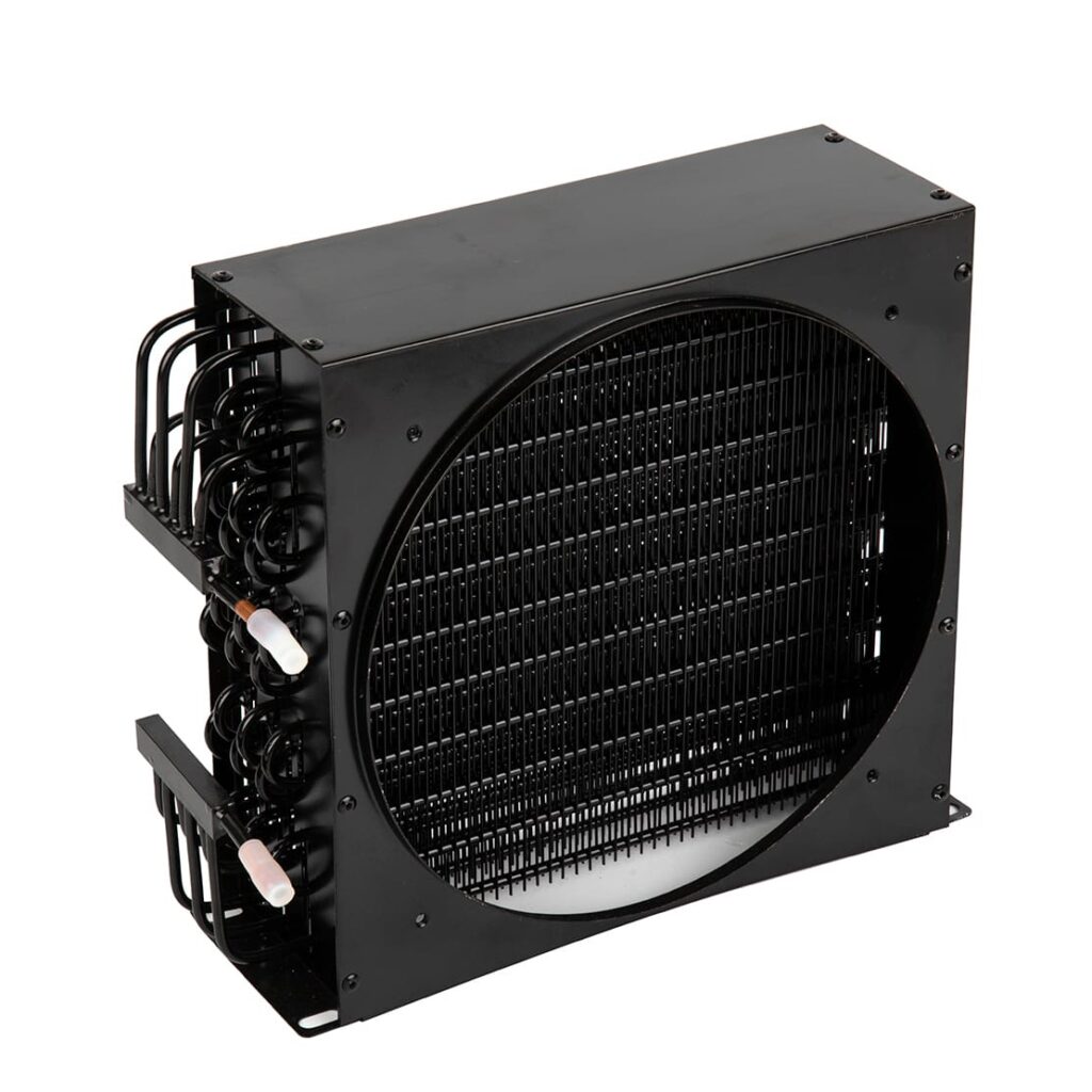
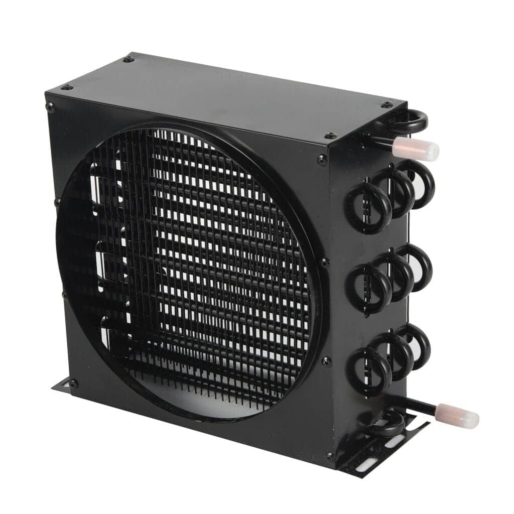
Get Product Information for Your Project
Send the product model, drawings, sample photos, quantity, or application requirements. Our team will review the information and help confirm suitable options, technical data, and quotation details.