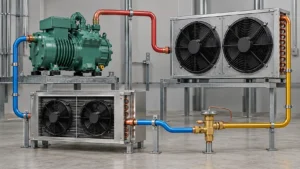
A commercial refrigeration coil calculation is a structured comparison between required heat duty and the coil’s air-side, refrigerant-side, mechanical, and control limits. It should identify the load, entering and leaving conditions, refrigerant, airflow, face velocity, pressure drops, frost or condensation, geometry, and rating basis rather than relying on a nominal tonnage number.
The phrase coil calculation can mean different things. An engineer may mean a heat-load estimate, an air-side calculation, a refrigerant circuit calculation, a pressure-drop check, or a supplier rating sheet. A procurement manager may use it to compare two coil quotations. A replacement buyer may only have a cabinet model and an old part. Those situations need different levels of data, but all benefit from clear assumptions.
This article applies the idea of a coil calculation to commercial refrigeration applications such as display cases, walk-in coolers, beverage equipment, food-service cabinets, ice machines, blast chillers, and replacement coils. It is a buyer and engineering input guide, not a substitute for a licensed design, equipment validation, refrigerant safety review, or the final supplier rating. Domi’s commercial refrigeration solutions page provides the broader application context.
The central rule is simple: do not compare a result without comparing its conditions. A coil rated at one entering-air temperature, airflow, refrigerant, and evaporating condition is not automatically equivalent to a coil rated at another. Make the conditions visible before debating fin pitch, rows, tube diameter, coating, or price.
What does a commercial coil calculation include?
A commercial refrigeration coil calculation normally connects four layers. The first is the thermal duty: how much heat the coil must absorb or reject. The second is the fluid and air condition: temperatures, pressures, flow, humidity, refrigerant, glycol or water where relevant. The third is the geometry: face area, depth, rows, tube pattern, fins, circuiting, headers, and connections. The fourth is the equipment constraint: cabinet space, fan, noise, frost, drain, service access, controls, materials, and installation.
The calculation may begin with a design estimate and end with a supplier rating. It should show which values are measured, which are assumed, and which are the result. If an input changes, the affected output should be identified. This is more useful than a single capacity number with no rating basis.
Evaporator and condenser calculations are different
An evaporator calculation focuses on heat absorbed from air, product, water, or another cooled medium. A condenser calculation focuses on heat rejected to air or water and includes compressor work. A walk-in cooler evaporator may need frost, defrost, drain, and humidity inputs. A commercial condenser may need ambient, fan, fouling, and subcooling inputs. Use the right heat exchanger role in the calculation title.
The phrase coil calculation should also identify whether the component is a direct-expansion refrigerant coil, a chilled-water or glycol coil, a wire-tube condenser, a fin-tube condenser, a microchannel core, or another construction. The method and assumptions can differ.
Rating standard and scope
Standards help make ratings comparable, but the scope must match the component. AHRI 410 covers certain forced-circulation air-cooling and air-heating coils and lists exclusions such as frosting conditions, microchannel coils, bare-tube coils, and several direct-expansion configurations. That means a buyer should not automatically describe every commercial refrigeration coil calculation as an AHRI 410 rating.
The calculation should name the standard, method, software, or internal procedure used. If the project is outside the scope of a standard, state that and define the alternative rating basis. The ASHRAE standards and guidelines resource can help teams locate relevant references, but the equipment designer remains responsible for selecting the appropriate method.
Step 1: Define the heat load
The heat load is the starting point for a coil calculation. It may include product pull-down, transmission through walls, infiltration, door openings, fan heat, lights, motors, defrost recovery, people, equipment, and adjacent processes. Not every item applies to every cabinet. The calculation should show the components and the time basis rather than hiding them inside a rounded total.
Product and process load
For a food-service cabinet or blast chiller, product mass, start temperature, target temperature, specific heat, phase change, container, loading schedule, and cycle time can dominate the duty. For a beverage cooler, repeated door openings and product loading may matter more than the steady cabinet load. For a walk-in cooler, infiltration and defrost may be important. Ask what the equipment must cool and how quickly it must do so.
The FDA Food Code 2022 provides regulatory context for cooling and cold holding of certain foods. It does not calculate a coil or validate an equipment cycle. Use the applicable food-safety requirement as a design boundary, then state the product and process assumptions in the coil calculation.
Transmission and infiltration
Transmission load crosses insulated walls, doors, floors, ceilings, and penetrations. Infiltration load enters with warm and humid air through openings, damaged gaskets, or normal operation. Humidity can turn into condensate or frost on an evaporator, so the latent part of the load should not be ignored when moisture enters the cabinet.
Internal heat sources
Fans, motors, lights, heaters, pumps, controls, people, and product-handling equipment add heat. A fan located upstream or downstream of the coil changes the air temperature used for the rating. A motor in the cabinet adds heat to the cooled space. A heater used during defrost adds a recovery load. Identify the location and operating schedule.
| Load item | Key input | Why it affects the coil calculation |
|---|---|---|
| Product or process | Mass, start and target condition, cycle time | Defines pull-down or continuous process duty |
| Walls and openings | Envelope, insulation, ambient, door schedule | Defines transmission and infiltration |
| Moisture | Humidity, air leakage, product moisture | Defines latent load, condensate or frost |
| Internal sources | Fan, motor, lights, people, heaters | Adds sensible heat and may change air state |
| Defrost and recovery | Method, duration, frequency, recovery target | Changes peak load and operating schedule |
The result should distinguish normal load from peak or pull-down load. A coil that meets average holding duty may not meet a short product loading event. Conversely, a coil sized for a brief peak may create excessive cycling or control difficulty during normal operation if the system cannot modulate appropriately.
Step 2: State air-side conditions
Air-side inputs include entering temperature, leaving temperature, relative humidity or dew point, airflow, density, face area, face velocity, pressure drop, bypass, and air direction. For a condenser, entering air may be ambient or recirculated equipment air. For an evaporator, the air may be wet, dry, or frosting. The coil calculation should state where the temperatures are measured.
Face area and face velocity
Face area is the open coil face available to the air. Face velocity is the average airflow divided by the effective face area. It is a useful screening value, but it does not show distribution. A coil with blocked sections, bypass gaps, uneven fans, or a nearby obstruction can have the same average velocity as a well-distributed coil.
High velocity can improve air-side heat transfer but may increase pressure drop, noise, carryover, and frost sensitivity. Low velocity can reduce pressure drop but may require more surface area or a larger cabinet. A coil calculation should show the tradeoff rather than treating face velocity as a target independent of fin spacing and air condition.
Moisture, condensate and frost
If the coil surface is below the air dew point, moisture condenses. If the surface is below freezing, frost may form. Frost increases thermal resistance and reduces free area. The calculation should identify whether the rating is dry, wet, or frosting, and whether the result includes a clean coil or an operating frost condition.
Drain pan, slope, outlet position, insulation, defrost, and recovery belong to the mechanical review. A calculated capacity on a clean surface does not prove that the cabinet will maintain performance over a frost cycle.
Air distribution and fan curve
Provide fan curve, speed, motor power, direction, static pressure, grille, baffle, and return-path information. If the fan is not selected, mark it as an open item. The supplier can calculate the coil pressure drop, but the equipment designer must confirm the fan can deliver the required airflow through the complete cabinet.
Step 3: Define refrigerant and fluid conditions
Refrigerant-side data includes refrigerant, inlet and outlet state, evaporating or condensing condition, mass flow, superheat or subcooling, allowable pressure drop, design pressure, test pressure, oil, control method, and circuiting. For water or glycol coils, include fluid temperature, flow, concentration, viscosity, pressure, freeze protection, and allowable pressure drop.
Commercial refrigeration is moving through different system architectures and refrigerant options. The EPA GreenChill advanced refrigeration page describes centralized, distributed, secondary-loop, cascade, transcritical carbon dioxide, and self-contained systems. A coil calculation should state which architecture applies because the refrigerant path and control conditions change.
Pressure and saturation conditions
Saturation temperature and pressure influence the temperature difference available for heat transfer. A proposal that uses a lower evaporating temperature may show more capacity but can change efficiency, frost, suction condition, and compressor selection. A condenser rating at a different condensing temperature may change the required surface and fan duty.
State the pressure measurement or calculation basis. If the system uses a pressure drop budget, show the allocation across distributor, coil, suction line, liquid line, valve, and other components. The coil should not consume the full pressure-drop allowance without the system engineer’s approval.
Refrigerant transition
If the refrigerant is changing, do not copy the old coil calculation and replace the name. Pressure, mass flow, density, oil, material compatibility, controls, safety classification, and design pressure may change. The EPA technology transition information provides current regulatory context for certain sectors, but a project team must determine the rule and compliance date that apply to its equipment.
Secondary fluids
Chilled water and glycol calculations need concentration and temperature because fluid properties affect heat transfer and pressure drop. Glycol also changes viscosity and pump duty. The calculation should state whether the fluid is clean, treated, or exposed to contamination and whether the coil is intended for cooling, heating, dehumidification, or process duty.
Step 4: Review coil geometry
Geometry is the result of the calculation and a constraint on it. State height, width, depth, rows, tube diameter, tube pattern, fin pitch, fin material, tube material, circuits, headers, connection positions, bracket locations, pan, insulation, and service access. A supplier may propose a different geometry to meet the duty, but the change should be visible.
Rows, fins and tube pattern
More rows or closer fins can increase area, but they can also increase air pressure drop, weight, moisture retention, and cleanability risk. A larger face can reduce velocity, but it may not fit the cabinet. Tube pattern, fin contact, joint method, and circuiting influence both heat transfer and manufacturing.
Circuiting
Circuiting controls how refrigerant or fluid uses the surface. It affects velocity, pressure drop, distribution, superheat, subcooling, and oil return. A circuit change may need a new header, distributor, connection, control, or test. The buyer should request a circuiting diagram when the rating is important or when the replacement differs from the old design.
Compact and microchannel constructions
Microchannel or flat multiport constructions can reduce internal volume and package size in some applications. They also require attention to distribution, header design, corrosion, joining, cleaning, repair, and pressure testing. Finned-tube construction may provide different geometry and service advantages. The coil calculation should compare the construction under the same duty and operating condition.
| Geometry item | Main tradeoff | What the calculation or drawing should show |
|---|---|---|
| Face area | Lower velocity versus cabinet size | Effective area, airflow and bypass assumption |
| Depth and rows | More surface versus air pressure drop and service | Rows, tube pattern, total depth, access |
| Fin pitch | Area versus frost, fouling and cleanability | Pitch, material, surface treatment if any |
| Circuiting | Distribution and pressure drop versus manufacturing | Circuit diagram, headers, connections |
| Connection layout | Piping and fit-up versus package flexibility | Centerlines, orientation, clearance and flow |
Step 5: Check pressure drop and fan or pump duty
Pressure drop is a system constraint. Air-side pressure drop affects fan selection, noise, power, and airflow. Refrigerant-side pressure drop affects available pressure difference, controls, distribution, and performance. Fluid-side pressure drop affects pump power and flow. A coil calculation should show each relevant pressure drop with the condition used.
Do not compare pressure-drop values without comparing density, viscosity, flow, fin condition, and whether headers are included. A water or glycol pressure drop may include the header, while a refrigerant value may exclude the distributor. Ask for scope and units.
Clean and operating conditions
A clean-coil pressure drop can be lower than an operating value when frost, dust, grease, or scale accumulates. If a project uses a maintenance limit, state how it is represented. The supplier can calculate the clean coil, but the equipment owner should decide when cleaning or defrost is required.
Noise and energy
Higher airflow and pressure drop can increase fan power and sound. A coil calculation that optimizes only thermal capacity may move the problem to the fan. State the noise-sensitive areas and the available motor or speed control. A low-noise requirement should be an equipment-level requirement with coil and fan assumptions recorded.
How to compare supplier coil calculations
Ask each supplier to return the same fields. The first comparison is the rating basis. The second is geometry and fit. The third is pressure drop, fan or pump requirement, and controls. The fourth is materials, coating, inspection, and documents. The final comparison is the commercial scope and open points.
The commercial cooling coils page is useful for application context, but it does not define the rating of a new coil. The cooling coils guide explains why air condition, fluid, dimensions, pressure drop, and moisture must be considered together. Keep those inputs separate from the final supplier result.
| Comparison block | Required questions | Record |
|---|---|---|
| Rating | Same load, air condition, refrigerant, flow and rating method? | Data sheet and assumptions |
| Geometry | Same envelope, rows, fins, circuits, connections and access? | Approved drawing and circuit sketch |
| System effect | Same air, refrigerant or fluid pressure drops and fan or pump? | Fan or pump requirement and deviation list |
| Durability | Same material, coating, cleaning, frost, vibration and environment? | Material and exposure statement |
| Quality | Same dimensional, leak, pressure, surface and documentation scope? | Inspection plan and records |
| Commercial | Same sample, quantity, packaging, delivery and change control? | Quote comparison and purchase scope |
When results disagree
If two calculations disagree, compare input conditions before comparing construction. Check capacity definition, sensible and total capacity, airflow, entering-air condition, refrigerant, evaporating or condensing temperature, pressure-drop scope, and whether the result includes frosting or fouling. Many differences are caused by rating basis rather than a mathematical error.
If the basis is identical and the result still differs, ask for the calculation method, performance correlations, software version, test data, or empirical basis. A supplier may not disclose proprietary equations, but the proposal should state enough information for the buyer to understand the result and its limits.
Replacement coil calculation
A replacement project may not have a full load calculation. Start with the old equipment model, coil dimensions, connections, fan, refrigerant, operating symptoms, and measured temperatures or pressures. Use the old part as an interface reference, not as proof that its capacity is correct. If the cabinet changed or the old part failed repeatedly, create a new operating review.
Field measurement quality
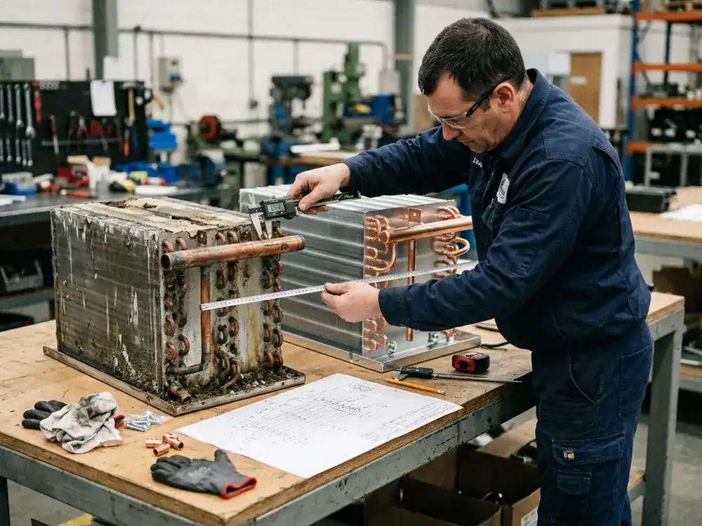
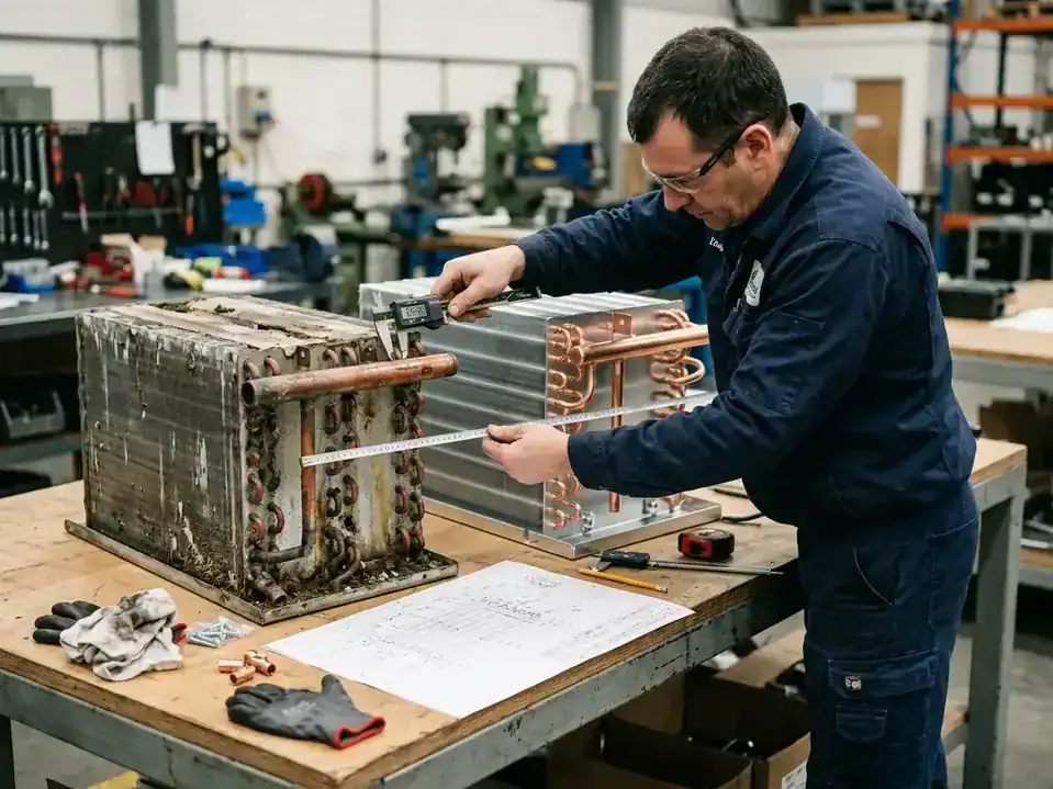
Measure face, depth, connections, brackets, clearances, fan, grille, and drain. Photograph the coil with a scale. Record whether the measurement was taken before or after fin damage, cleaning, repair, or insulation removal. Note the instrument and location for temperatures or pressures.
Failure patterns
Corrosion, leak, frost, high pressure, poor airflow, noise, and inadequate cooling require different questions. A replacement coil calculation should include the failure pattern and maintenance history. If the cause is not known, state that the replacement is a feasibility review rather than a guaranteed correction.
From a coil calculation to an approved drawing
A calculation becomes useful to production and procurement only when its result is connected to a controlled drawing. The drawing should show overall envelope, face area, rows, tube pattern, fin pitch, circuiting, headers, connections, brackets, pan or drain, airflow direction, datum, and the revision that the calculation represents. If the drawing leaves out an important assumption, a later team may build a different part while believing it is the same design.
The coil calculation should have an input section, a result section, and an open-point section. The input section lists load, temperatures, humidity, refrigerant, flow, pressure limits, and geometry assumptions. The result section lists capacity, pressure drops, face velocity, surface condition, and any fan or pump requirement. The open-point section lists data that must be confirmed by the equipment owner, such as final refrigerant, ambient, product load, cleaning method, coating, or test standard.
Freeze and defrost applications
If the evaporator operates below freezing, the calculation should state how frost is represented. A clean, dry rating may be suitable for a laboratory reference but not for a low-temperature cabinet after a long operating cycle. State the defrost type, interval, duration, drain path, and recovery target. If the result is intended for a blast chiller or blast freezer, record the product load and the point in the cycle at which the rating is checked.
Condenser and high-ambient applications
If the coil is a condenser, state ambient, recirculation, fan control, grille, fouling, and subcooling. A high-ambient design may need more surface or different airflow than a comfortable indoor rating. If the condenser is remote, include installation orientation, air clearance, weather exposure, and service access. Do not transfer the conditions from an evaporator calculation to a condenser without rebuilding the heat-rejection basis.
Review risk before changing geometry
A supplier may propose a larger face, extra rows, different fins, alternate material, a new header, or a different circuit pattern. Treat every proposal as a design change until its effects are recorded. A larger coil can require a new fan, bracket, pan, grille, or cabinet opening. A tighter fin pitch can change pressure drop and cleaning. A new circuit may change controls and connection orientation. A coating can affect surface and joint treatment.
The calculation should be updated with the proposed geometry and the revision should be marked on the drawing. The buyer should ask which outputs changed and whether the system needs a new test. This prevents a performance improvement in a spreadsheet from becoming a fit-up or service problem in the field.
Test plan and acceptance criteria
Define what the test will prove. A dimensional inspection proves geometry. A pressure or leak test proves the relevant circuit under the agreed procedure. A thermal test checks capacity or air and fluid conditions. A cabinet test checks the complete equipment. A production test may check cycle, ice form, pull-down, or holding performance. The test owner, equipment, sensors, conditions, tolerances, and record format should be agreed before the sample is built.
The coil calculation should not be treated as a test result. It is a design or rating tool. The test can confirm, calibrate, or challenge the calculation. If the test and calculation disagree, compare the actual airflow, temperatures, refrigerant, sensor position, surface condition, fan, control setting, and measurement uncertainty before changing the design.

Hand-off to procurement and service
Procurement needs a part description that matches the approved drawing. Service needs an identification method, replacement boundary, connection information, and any installation or cleaning instruction. Quality needs an inspection plan that reflects the drawing and the calculation. Sales or project management needs a scope that does not promise unverified capacity, timing, or certification.
The hand-off should include the final input record, calculation revision, drawing revision, open-point closure, sample result, and approval owner. If the equipment uses multiple variants, show which inputs are common and which change by model. A controlled hand-off is especially important for refrigeration condenser coils and evaporator families because a small change in rows, connections, or circuiting may affect several downstream documents.
Keep calculation boundaries honest
A practical coil calculation can be useful even when the input data is incomplete, provided the boundary is clear. Call the result a screening estimate, budgetary rating, sample rating, or final design rating. Each label tells the next reader how much confidence to place in it. A screening estimate can guide the cabinet envelope. A sample rating can support a prototype discussion. A final design rating should reflect the approved equipment conditions and drawing.
When a number is carried from an old data sheet, record its source and date in the project file. When a number is estimated from a catalog, label it as an estimate. When a supplier provides the result, keep the supplier’s assumptions and scope. This small discipline prevents an early coil calculation from becoming an unverified promise in a later purchase order or product page.
The same boundary should appear in the article, quotation, drawing, and internal spreadsheet. If a value is only a target, use target language. If a value is measured, identify the measurement. If a result is pending a sample, say so. Clear language protects the buyer and gives the supplier room to ask for the data that will actually change the design.
That record is especially valuable when several suppliers are being compared or when a replacement moves from service to repeat distribution.
It also keeps later maintenance questions tied to the design basis.
A Domi review path from calculation to quote
Send the application, equipment type, load, air or fluid conditions, refrigerant, airflow, pressure-drop limits, envelope, materials, coating exposure, quantity, and destination to Domi through the contact page. For a new design, include the equipment drawing and control intent. For a replacement, include old-part photos, measurements, connections, fan, refrigerant, and failure pattern.
The commercial refrigeration solutions page provides the hub for display cases, walk-in coolers, beverage equipment, food-service equipment, ice machines, blast chillers, and related components. Domi can review the information that is available and identify missing data for a project-specific discussion. Final capacity, pressure, materials, performance, testing, timing, and commercial terms must be confirmed against approved project documents.
Coil calculation FAQ
What is a coil calculation?
A coil calculation estimates or rates a heat exchanger under defined thermal, air-side, fluid-side, refrigerant, geometry, and equipment conditions. It may include heat load, capacity, air or fluid flow, pressure drop, surface condition, and operating limits. The result is only meaningful when the assumptions are visible.
How do I calculate a refrigeration coil size?
Define the load, entering and leaving conditions, refrigerant or fluid, airflow or flow rate, allowable pressure drops, frost or condensation, envelope, and operating schedule. Then use an appropriate design method or supplier rating. A nominal tonnage number without those inputs is not a complete coil calculation.
What is face velocity in a coil calculation?
Face velocity is the average airflow divided by the effective coil face area. It helps compare air-side designs, but it does not show distribution, bypass, fan coverage, frost, or fouling. Use it with pressure drop, fin spacing, air condition, and cabinet layout.
Why does pressure drop matter?
Air-side pressure drop affects fan airflow, power, noise, and control. Refrigerant-side pressure drop affects available pressure difference, distribution, superheat or subcooling, and system performance. Fluid-side pressure drop affects pump duty and flow. Each value needs a clear scope and rating condition.
Does more coil area always mean better performance?
No. More area may improve capacity under one condition, but it can increase cost, weight, pressure drop, frost retention, cleaning difficulty, or cabinet size. The design should balance thermal duty with airflow, refrigerant distribution, service, materials, and controls.
Can I use AHRI 410 for every commercial refrigeration coil?
No. AHRI 410 has a defined scope and lists exclusions that include frosting conditions, microchannel coils, bare-tube coils, and several direct-expansion configurations. Check the scope and identify the actual rating method for the project.
What inputs are needed for a replacement coil calculation?
Provide the old coil, dimensions, connections, fan, refrigerant, equipment model, operating symptoms, measured conditions, failure environment, quantity, and destination. A replacement calculation should also state whether the goal is fit-only, capacity matching, a redesign, or a failure correction.
Can Domi calculate a coil from a drawing?
A drawing is a useful starting point. The review may also need load, air or fluid conditions, refrigerant, airflow, pressure limits, frost or condensation, materials, coating exposure, and quantity. Domi can identify the missing inputs and confirm what can be discussed for the specific project.