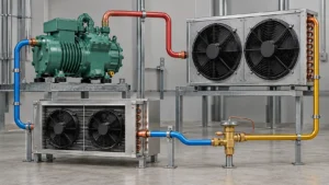
A refrigerator defrost heater melts frost from the evaporator during a controlled cycle; a failed heater can reduce airflow, warm the fresh-food compartment, and create a symptom that looks like a bad coil.
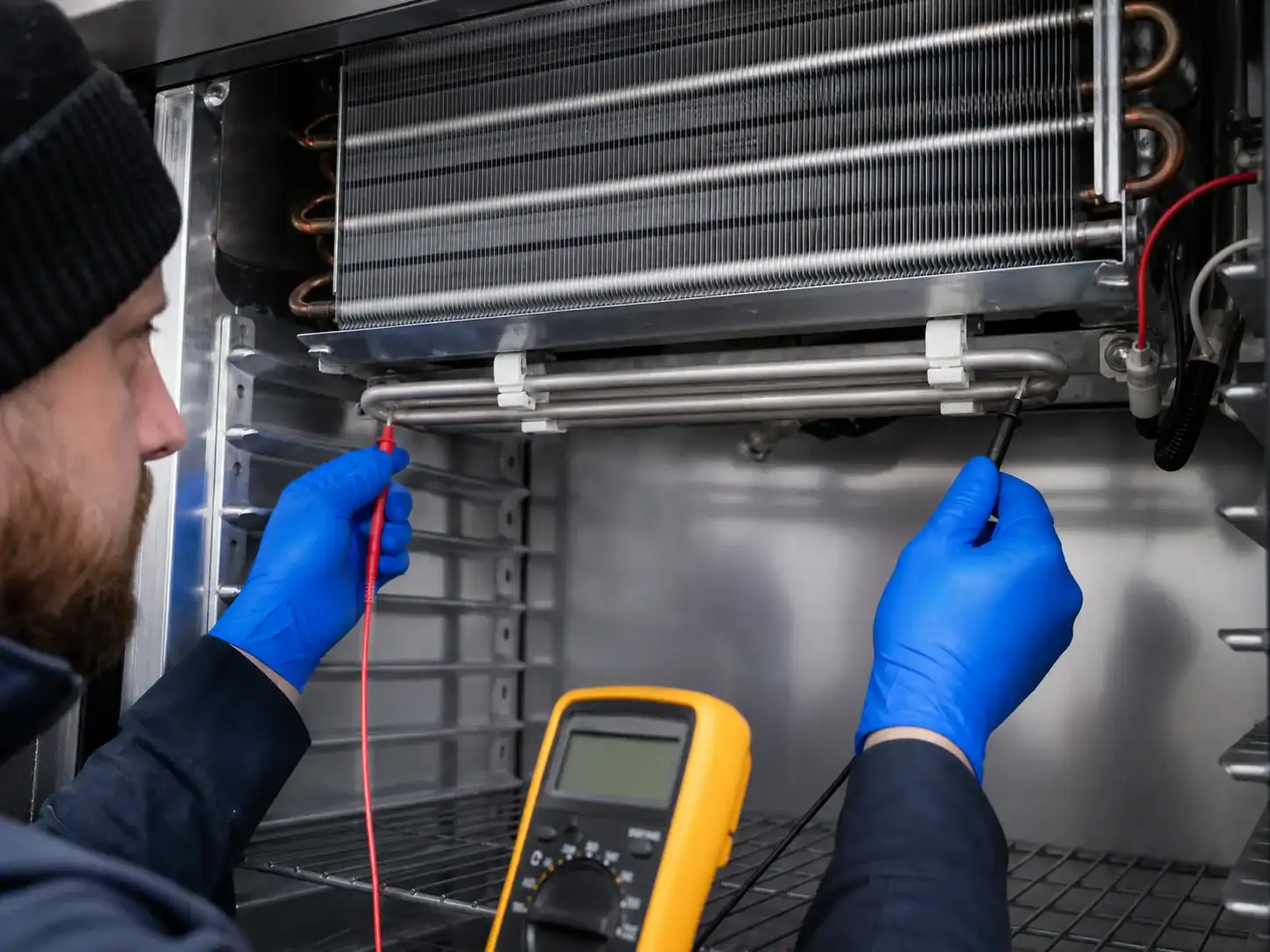
A refrigerator defrost heater is a small component with a system-level job. It supplies controlled heat to the evaporator area so accumulated frost can be removed without damaging insulation, plastic parts, wiring, food-zone materials, or the coil assembly. When the heater does not operate, the refrigerator may cool normally for a period and then lose airflow as ice covers the evaporator. The resulting complaint can be “refrigerator not cooling,” “freezer works but refrigerator is warm,” or “cooling returns after a manual defrost.”
This guide explains what the defrost heater does, how failure symptoms should be separated from sensor or control faults, what a qualified technician can test, and what an OEM should include in a replacement or custom-coil RFQ. The heater and thermostat are treated as project interfaces unless the scope is confirmed; this article does not assume that a refrigeration-coil supplier automatically manufactures or supplies every electrical defrost component.
The GE explanation of refrigerator defrost systems is a useful reference for the different automatic-defrost approaches used in appliances. The GE automatic-defrost overview also explains why frost removal is part of normal operation rather than a sign that the refrigerator should never contain frost. For a custom evaporator, the correct heater location and test conditions must come from the appliance design, not a generic internet specification.
What a refrigerator defrost heater does
An evaporator operates below the dew point of cabinet air, so moisture can condense and freeze on its fin pack. A thin frost layer may be expected during operation, but excessive frost reduces open fin area, increases air-side resistance, blocks the fan or ducts, and lowers heat transfer. A defrost heater temporarily adds heat to the evaporator zone so the frost melts and drains away.
The heater is part of a defrost system
The heater normally works with a control board or timer, a thermostat or temperature sensor, a termination condition, a drain, a cover or shield, and an evaporator coil. The cycle must deliver enough heat for the expected frost load while stopping before the surrounding materials overheat.
| System element | Role during defrost | Failure that can look like a heater problem |
|---|---|---|
| Defrost heater | Adds controlled heat to melt frost | Open element, wrong resistance, poor mounting or no power |
| Defrost thermostat | Enables or interrupts heat based on temperature | Wrong model, open/closed at the wrong temperature, poor contact |
| Thermistor/sensor | Reports temperature to the control | Drift, wrong location, damaged harness or connector |
| Timer/control board | Starts, controls and terminates the cycle | No command, wrong software state, relay fault |
| Drain and pan | Carries meltwater away | Blockage, poor slope, refreezing or insufficient heat transfer |
| Coil and cover | Provide the heat-transfer and protected geometry | Ice bypass, damaged fins, blocked airflow or wrong interface |
Because the elements interact, continuity across the heater alone does not prove that the defrost system works. Conversely, a cold or open heater reading may be expected if the heater is being measured outside the correct test state or with the thermostat open.
Symptoms of a failed or misapplied defrost heater
Cooling improves after manual defrost
If a complete safe defrost restores airflow and cabinet temperature, ice restriction is likely part of the problem. The heater may be open, disconnected, incorrectly positioned, or never commanded. The cause could also be a sensor, control, drain, gasket, or high-moisture load. Record how long the appliance performs after defrost; a repeat interval can help show whether the cycle is completing.
Freezer is cold but refrigerator compartment is warm
In many layouts, the fresh-food compartment depends on air passing across the evaporator. A frost block can leave the freezer cold near the coil while restricting the supply path to the other compartment. Check the fan, vents, return path, damper, frost, and defrost components before ordering a replacement coil. The Domi guide to a refrigerator that is not cooling while the freezer works covers this diagnostic branch in more detail.
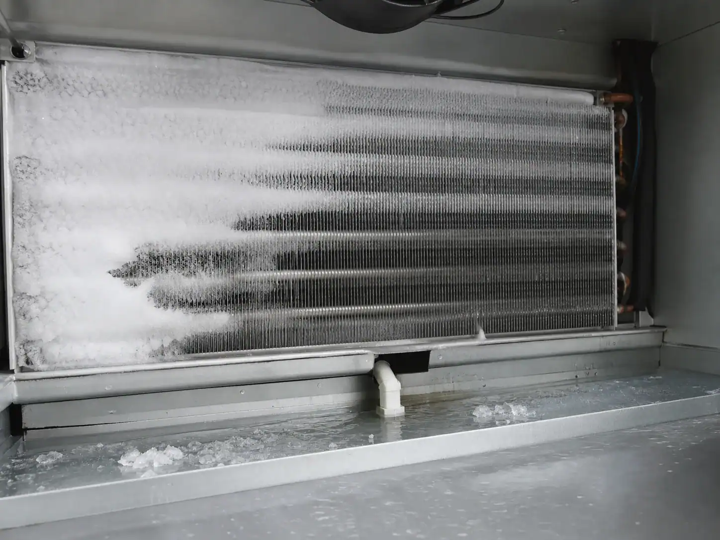
Frost grows into a solid layer
Continuous frost across the evaporator reduces airflow. A heater that is too small for the frost load, incorrectly spaced from the coil, shielded by a cover, or located away from the coldest area may not clear the fin pack. If frost grows only at a drain or corner, inspect moisture entry, drain geometry, airflow bypass, and sensor placement instead of assuming the heater wattage is the only issue.
Meltwater refreezes after a cycle
The heater may be working while the drain, pan, insulation, or airflow path causes water to freeze again. Check the slope and outlet, the drain heat path, the pan position, and whether a cover directs cold air over the water. A new coil should not be approved without reviewing the drain and defrost recovery condition.
How qualified technicians evaluate a defrost heater
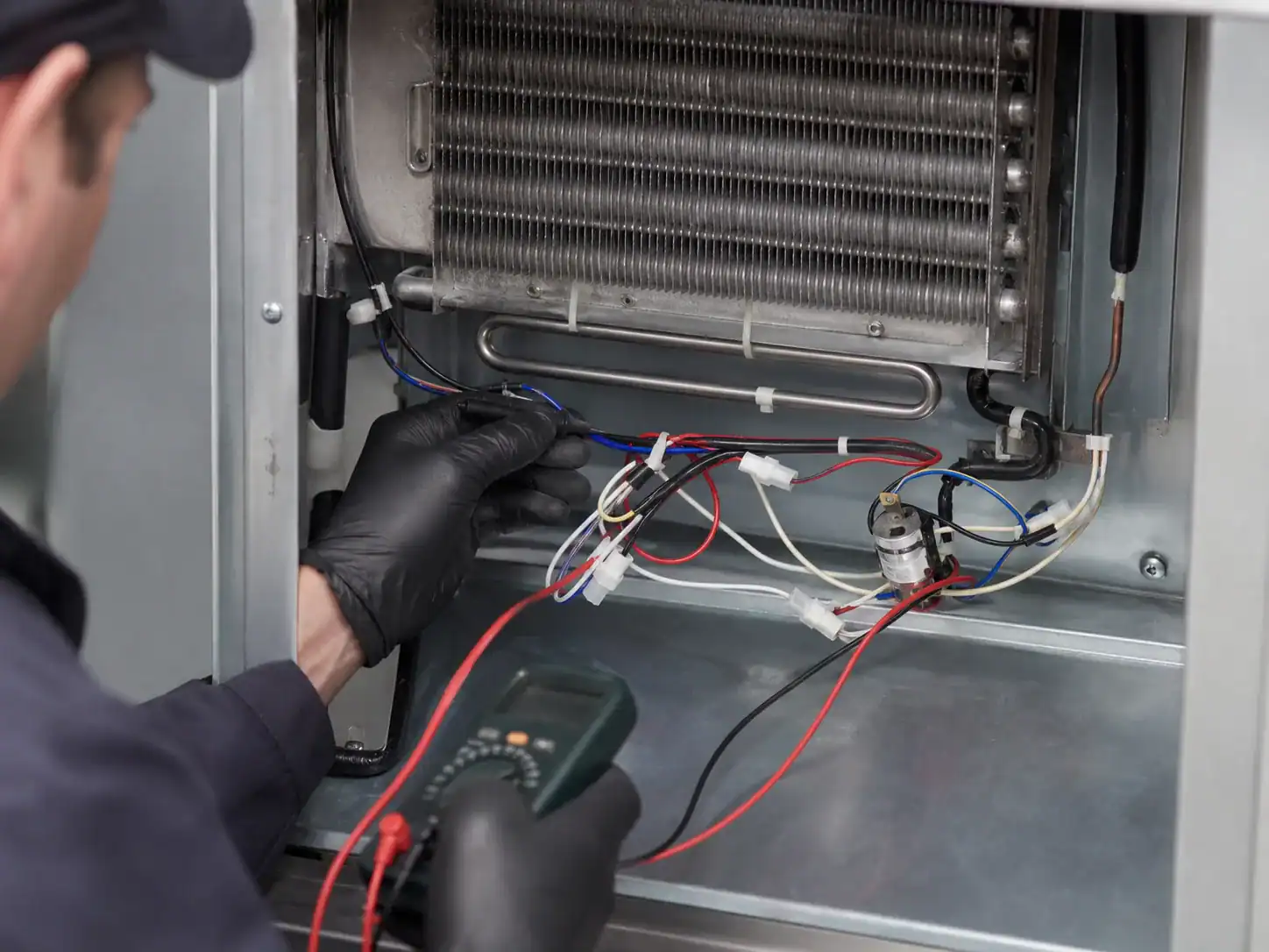
Electrical and thermal tests should follow the appliance service manual. Disconnect power before access, use the correct meter range, and do not bypass safety devices as a permanent repair. If the appliance has refrigerant tubing near the heater, avoid damaging the sealed system or insulation.
Visual and mechanical inspection
Inspect the heater body, terminals, connector, harness routing, clips, supports, shields, and signs of overheating, corrosion, arcing, or physical contact with fins. A heater can be electrically intact but mechanically displaced. Check whether ice or a foreign object prevents the heater from transferring heat to the intended area.
Look for an evaporator cover that is warped, missing, or not sealed. A cover change can alter air movement and heater exposure. If the design has a sensor clipped to the coil, record the sensor location and whether it has good thermal contact.
Continuity and resistance
An open circuit can indicate a broken element, terminal, connector, harness, or protective device. A resistance value that appears plausible still needs comparison with the model’s service data and the heater’s rated voltage. Do not substitute a value from another model. A low-resistance reading can also be distorted by parallel paths if the component is not isolated from the circuit.
Command and current
The control must deliver the correct command at the correct stage of the cycle. Verify the service-test state, voltage, current, duration, termination, and safety cutout as specified. A no-heat result with no command points to the control, sensor, thermostat, wiring, or test procedure—not necessarily the heater element.
Temperature response
Where the procedure allows it, observe temperature change at the heater and evaporator zone. Confirm that the sensor or thermostat responds as intended and that the cycle terminates. Do not use an uncontrolled high-temperature source to imitate a heater. The GE defrost thermostat product information illustrates why the correct thermostat is model-specific and why temperature and mounting matter.
Drain and recovery
After defrost, verify that water leaves the pan, the drain does not refreeze, the fan restarts, and the cabinet returns to its target. A heater that clears the top of the coil while the lower drain remains blocked is not a complete solution.
Heater types and design choices
Appliance designs use different heater constructions and placements. The choice may depend on coil geometry, voltage, available space, defrost control, materials, cleaning, and safety constraints.
Sheathed or tubular heaters
These use a resistive element protected by a sheath and are often formed to follow a coil or support. The mounting clips, bend radius, terminal direction, clearances, and corrosion environment matter. A mechanically similar heater can have different power, temperature, terminal, or insulation characteristics.
Glass or wire-style elements
Some designs use a protected wire or glass tube arrangement. The component must be supported against vibration and kept away from plastics or insulation that are not rated for the local temperature. The replacement must match the approved part and service procedure.
Drain or pan heating provisions
Some systems provide a separate heat path around the drain or pan. Do not treat a drain heater as a substitute for an evaporator heater. The two locations solve different problems and must be tested under the actual frost and meltwater conditions.
Integrated versus replaceable assemblies
The heater may be a separate service part or assembled with brackets, harnesses, sensors, clips, or the evaporator. For procurement, confirm whether the quote is for a bare element, a coil with heater, or a complete evaporator assembly. For service, the parts list should make the distinction unambiguous.
Defrost heater and evaporator coil interfaces
An evaporator coil drawing should show the heater relationship when the coil supplier or assembler controls the geometry. Include heater keep-out, support points, sensor or thermostat clip location, drain outlet, cover clearances, insulation, wiring exit, and the orientation used during assembly.
Heat transfer and clearance
The heater must be close enough to remove frost but not so close that it damages the coil, fin coating, insulation, plastic, wire insulation, or cabinet liner. A fin pitch or header change can alter heater access and frost distribution. Record the intended assembly tolerance.
Sensor contact and termination
If the sensor or thermostat clips to the coil, show the exact tube or fin location and contact requirement. A few millimeters can change the temperature seen by the control. If the sensor is mounted on a bracket or cover, the replacement coil should preserve that interface or include a controlled change.
Drain and water management
Document drain alignment, slope, pan contact, heat path, and the lowest point of the assembly. Water should not flow toward electrical connectors, insulation gaps, or a cold-air path where it can refreeze. Validate the drain after a full frost-and-defrost test, not only after pouring a small amount of water through a clean coil.
OEM validation plan for a defrost heater
The validation plan should expose both the normal and abnormal conditions that affect the heater.
| Validation area | Example evidence |
|---|---|
| Electrical | Rated voltage, resistance, current, connector and insulation checks |
| Thermal | Heater temperature, coil temperature, sensor response and termination |
| Frost | Frost load, distribution, blocked-fin threshold and cycle repeatability |
| Drain | Meltwater flow, pan capacity, refreeze check and cabinet recovery |
| Airflow | Supply/return flow before frost, during frost and after defrost |
| Materials | Compatibility with moisture, refrigerant environment, coatings and plastics |
| Safety | Clearances, protective devices, abnormal-condition test and service access |
| Production | Mounting poka-yoke, inspection points, wiring route and traceability |
Use the appliance’s approved limits. Do not invent a universal heater wattage, duration, or termination temperature for a product family. The Danfoss defrost handbook provides system-level context for defrost sequencing, heat load, and control trade-offs; it is not a substitute for the appliance’s safety and performance validation.
Replacement data for a defrost heater or coil
The buyer should provide the exact appliance model and component identification. Useful data includes:
- Heater part number, rated voltage, resistance or power from the approved service data, terminals, harness, and connector.
- Evaporator drawing and revision, coil envelope, tube size, circuiting, fin pitch, material, coating, and connection orientation.
- Heater form, support clips, sensor or thermostat position, drain, pan, cover, insulation, and keep-out zones.
- Refrigerant, operating temperatures, design pressure, frost load, defrost interval, maximum cycle time, and recovery requirement.
- Cabinet layout, fan, shroud, duct, airflow, ambient, setpoint, load, door-opening profile, and moisture exposure.
- Inspection and testing: dimensional report, continuity, current, insulation, leak or pressure test, defrost cycle, drain, and cabinet validation.
- Sample quantity, annual volume, MOQ, packaging, label, lead time, and change-notification requirements.
The Domi custom refrigeration coil quotation checklist can help structure the drawing, system, quality, and commercial handoff. If the project is a coil-only request, clearly state that the heater, thermostat, sensor, clips, and harness are customer-supplied or require separate confirmation.
What not to do with a defrost heater
Do not bypass a thermostat, fuse, sensor, or control because the refrigerator is warm. Do not install a heater with an unverified voltage, resistance, wattage, terminal, or form. Do not route a harness against a hot or sharp surface. Do not place the heater in contact with insulation or plastic outside the approved design. Do not chip ice with a sharp tool near the coil or tube. Do not release a changed heater or coil without updating the drawing, service record, inspection, and validation plan.
A controlled troubleshooting sequence
Use this sequence to keep the symptom and the component decision aligned:
- Confirm temperatures, airflow, fan state, frost pattern, and cabinet conditions.
- Verify that a defrost cycle is required by the design and that the control attempts it.
- Inspect heater, harness, connector, thermostat or sensor, clips, cover, and clearances.
- Test heater continuity and the control command according to the model service procedure.
- Observe thermal response, termination, drain flow, and post-defrost recovery.
- If the cycle passes, investigate fan, damper, return air, door seal, charge, restriction, or compressor conditions.
- If the coil or heater interface is damaged or under-designed, define a controlled replacement and validate the complete assembly.
Defrost heater troubleshooting by evidence
The symptom is easier to manage when each observation leads to a specific next check. The table below is a starting framework; the appliance service manual and safety requirements remain controlling.
| Observed condition | Do not conclude immediately | Next evidence to collect |
|---|---|---|
| Heavy ice on evaporator | Heater is definitely open | Heater command, continuity, sensor/thermostat state, drain, door moisture |
| Heater has continuity | Heater is working in the system | Rated voltage, current, mounting, temperature response and termination |
| No voltage at heater | Control board is failed | Defrost request, sensor input, thermostat, wiring, connector and protection |
| Heater gets hot | Defrost problem is solved | Ice clearance, meltwater drainage, fan restart and recurrence interval |
| Top coil clear, lower drain frozen | Coil geometry is wrong | Drain slope, pan, drain heat path, insulation and cold-air exposure |
| Fresh-food compartment warm | Evaporator coil needs replacement | Fan, damper, vents, return path, frost pattern, charge and control |
Heater failure versus a defrost-command failure
An open element is a component failure. No heater voltage can be a control or interlock failure. The distinction matters because replacing the element will not restore a missing command. Capture the test state, door switch condition, sensor temperature, cycle stage, connector measurement, and the appliance’s expected result. If the control uses an adaptive algorithm, record the service test procedure rather than waiting for an unknown automatic cycle.
Heater failure versus a drain failure
If the heater melts frost but the water refreezes, the refrigerator can show the same warm-compartment symptom again. Inspect the drain after a complete defrost, including the area below the coil and the pan outlet. Verify that water does not contact a cold duct, fan, connector, or insulation gap. A drain restriction can be intermittent when the appliance is level in the factory but tilted during installation, so include installation tolerance in the design review.
Heater failure versus excessive moisture load
A sound heater and defrost cycle may be unable to keep up with a damaged gasket, door misalignment, repeated door openings, warm humid air, uncovered liquids, or a cabinet leak. Compare the frost load with a controlled test and inspect gasket compression and cabinet sealing. The ENERGY STAR refrigerator guidance reinforces the practical importance of door seals, clearance, and airflow for normal performance.
Electrical and thermal safety boundaries
Defrost heaters operate at a voltage and temperature that can create shock, burn, fire, or material-damage risks. The service procedure should specify power isolation, access panels, protective devices, test equipment, thermal limits, and reassembly checks. Never leave a bypassed thermostat, fuse, sensor, or door interlock in a customer appliance or production sample.
Materials near the heater
Review the temperature rating of insulation, liners, wires, clips, coatings, adhesives, drain parts, and packaging remnants. A material change that is acceptable during normal cooling may not be acceptable near the heater. If a coil supplier proposes a different coating, tube, bracket, fin, or clip, request a compatibility review and update the approved part definition.
Electrical isolation and moisture
Connectors and terminals should remain protected from meltwater, condensation, cleaning liquid, and sharp edges. The heater harness should have strain relief and a defined route. In a replacement assembly, confirm connector keying and polarity where applicable; a connector that plugs in but routes heat or current incorrectly is not an acceptable substitute.
Abnormal-condition testing
Consider blocked airflow, failed fan, blocked drain, sensor misplacement, door open, high ambient, repeated defrost, low voltage, and a stuck control output as part of the safety assessment. The exact tests depend on the product and applicable standards. The purpose is to show that a single fault does not create an unsafe thermal condition.
Production and inspection controls
If the heater is assembled with an evaporator coil, production needs a way to verify repeatable position. Useful controls include a forming fixture, a clip or bracket poka-yoke, a photo standard, terminal pull check, connector verification, continuity, insulation or dielectric test where specified, dimensional inspection, and traceability to the coil drawing revision.
| Production point | Example check | Record |
|---|---|---|
| Incoming heater | Part number, voltage, resistance, terminals | Lot and supplier record |
| Forming | Bend location, radius, support and clearance | First-piece and sample inspection |
| Coil assembly | Heater and sensor location, clips, cover and drain | Assembly checklist or photo |
| Electrical | Continuity, current or insulation as required | Test result and instrument ID |
| Leak/pressure | Coil boundary and joints after assembly | Test report tied to revision |
| Defrost function | Thermal response, termination and drainage | Validation or audit record |
| Packaging | Protect element, terminals, fins and connectors | Pack-out inspection |
The Domi refrigeration coil MOQ guide can help the buyer frame sample, pilot, and production quantities. If the heater is a customer-supplied part, define who controls incoming inspection, replacement compatibility, and change notification. If the supplier assembles the heater, define the released supplier part number and change-approval route.
How to handle a heater revision
Create a new revision when the heater form, power, material, terminal, support, location, sensor relationship, drain, cover, refrigerant-side coil, or safety clearance changes. The change record should state whether the revision is a drawing-only correction, prototype change, pilot release, or production release. It should also state what happens to old heaters, coils, samples, packaging, service inventory, and open purchase orders.
Before approving the revision, compare the old and new assembly in the cabinet. Verify capacity and airflow before frost, frost distribution, defrost time, heater temperature, sensor response, meltwater path, post-defrost recovery, noise, and abnormal conditions. Keep the test report with the same part and revision identifiers used on the drawing and quotation. A new heater that works on a bench but cannot clear the cabinet’s actual frost pattern is not a successful change.
Design questions before selecting power
Heater power should be selected from the frost load, available defrost time, coil mass, cabinet materials, thermal paths, drain behavior, control strategy, and safety limits. A higher nominal wattage is not automatically better: it may raise local temperature, increase energy use, stress the protective device, or heat a component that should remain cool. A lower value may leave ice in the lower fin pack or drain. The engineering team should define the target frost condition and measure the temperature distribution rather than choosing from physical shape alone.
Document the service replacement boundary
The service manual should tell the technician whether the heater is replaceable alone, supplied with the evaporator, or replaced as a complete assembly. Include connector identity, routing, clips, sensor position, insulation, drain parts, test steps, and the post-repair verification. A clear boundary reduces improvised field substitutions and gives procurement a consistent part definition.
For a B2B quotation, ask the supplier to return an assumptions list with the offer. It should identify the assumed heater scope, model or drawing revision, electrical data, materials, fixture or tooling needs, sample quantity, inspection records, packaging, MOQ, lead time, and exclusions. This is especially important when an incoming request uses “defrost heater” as a search term but the actual need is a matched evaporator assembly with a controlled heater interface.
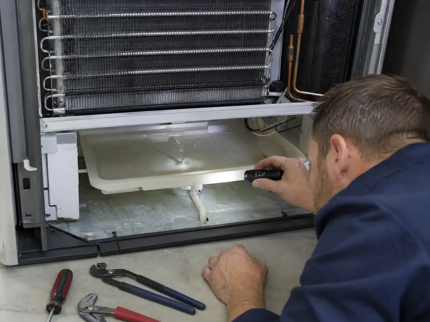
The final review should also record who owns the heater, thermostat, sensor, clips, drain, and cover. If any item is customer-supplied, the coil drawing and purchase release should identify the interface and inspection responsibility. That small ownership note prevents a supplier from making an unapproved electrical substitution when a request only described a “defrost heater.”
For production samples, record the heater’s position before the cover is fitted and after the assembly is complete. Check that the harness cannot contact the element, fins, drain water, or a sharp bracket. Confirm that the sensor or thermostat remains on the approved surface after transport and installation. These simple photographs and checks help quality distinguish an incoming component failure from an assembly or handling error.
Keep the same part and revision on the sample label, test record, and purchase release.
When a sample passes, retain the heater position, sensor position, drain condition, and post-defrost recovery evidence with the report. Those details make later service replacement and supplier change review possible.
Keep the component boundary clear in the quotation
An RFQ may use “defrost heater” as a convenient search phrase while the actual requirement is a matched evaporator assembly. Ask the buyer to identify whether the heater is already approved, whether the supplier must source it, whether the thermostat or thermistor is included, and whether the coil drawing controls the heater clip and drain. If the answer is not known, return an assumptions list instead of silently selecting a similar element.
This is particularly important when an old heater has failed inside a cabinet with a different control strategy. The same physical form may have a different power, voltage, contact arrangement, temperature limit, or harness. A supplier review should connect the heater to the coil, cover, sensor, drain, fan, and control test. The final sample report should show the installed orientation and the post-defrost recovery, not only a resistance measurement on a workbench.
Document the ownership boundary before the sample is approved, not after the first production issue.
FAQ: refrigerator defrost heater
What is the purpose of a refrigerator defrost heater?
It supplies controlled heat to the evaporator area so frost can melt and drain during an automatic defrost cycle. Without effective defrost, ice can restrict airflow and reduce cabinet cooling even when the compressor and fan initially operate.
How do I know if the defrost heater is bad?
A qualified technician should compare visual condition, continuity or resistance, the control command, current, temperature response, thermostat or sensor behavior, and drain recovery with the appliance service data. An open heater or no heat with a confirmed command can support a failure finding, but the whole circuit should be checked.
Can a bad defrost thermostat look like a bad heater?
Yes. A thermostat or sensor can prevent the heater from being energized or terminate the cycle incorrectly. Test the model-specific temperature behavior and mounting, not only heater continuity.
Does a refrigerator defrost heater run continuously?
No. It normally operates during a controlled defrost period and then stops before cooling resumes. The exact interval, duration, termination, and protection depend on the appliance design.
Why does the refrigerator cool after I defrost it?
Manual defrost removes ice that was blocking the evaporator or air path. If cooling later fails again, inspect the automatic defrost system, drain, door seal, fan, control, sensor, and moisture load to find the recurring cause.
Can any heater with the same shape be used?
No. Voltage, power, resistance, terminal, insulation, mounting, clearances, temperature response, and model compatibility must match. A similar shape can still create an electrical or thermal safety problem.
Does a custom coil quote include the defrost heater?
Not automatically. Confirm whether the supplier is quoting a bare coil, coil with heater, or complete evaporator assembly. Heater, thermostat, sensor, clips, harness, drain, and cover should be listed explicitly as included, customer-supplied, or subject to project review.
What should an OEM provide for a defrost-heater RFQ?
Provide the model and part number, drawing revision, heater electrical data, form and mounting, sensor or thermostat interface, coil and cabinet geometry, refrigerant and operating conditions, frost and defrost requirements, drain, testing, sample, volume, MOQ, packaging, and schedule.