
Static pressure is the local pressure a fluid exerts, excluding the pressure associated with its bulk velocity. Air can have static pressure while it is moving. In HVAC and refrigeration, static readings help describe the air path, but a useful result also identifies the measurement locations, reference pressure, airflow and equipment boundary. A pressure reading alone does not establish airflow or prove that a coil and fan will work together.
A fan selected by nominal airflow can miss the required cooling duty once the filter, wet coil, guards and cabinet are installed. The pressure budget explains where that difference comes from. This guide covers the definitions first, then shows how to reconcile a measured pressure with the supplier’s curve and component ratings.
The illustrations show generic engineering concepts. Numerical examples are hypothetical calculations, not Domi product ratings or test records.
Jump to pressure definitions, signed readings, measurement, pressure budget, coil comparison, or RFQ inputs.
Separate static, velocity and fan pressure
Static pressure, velocity pressure and total pressure describe different parts of the same airflow state. For the low-speed, approximately incompressible airflows considered here:
pᵥ = ρV² / 2
pₜ = pₛ + pᵥ
Here, ρ is air density in kg/m³, V is local air speed in m/s, and each pressure is in Pa. At 1.2 kg/m³ and 5 m/s, the velocity pressure is 15 Pa. This is a hypothetical calculation, not a fan rating.
A static tap senses local pressure without deliberately facing its opening into the stream. A total-pressure probe faces upstream. The exact probe design matters: a purpose-made static probe may have a tip aligned with the flow while its sensing holes face sideways. Follow its instructions rather than treating any open hose as an equivalent instrument.

Fan terminology adds another distinction. Fan total pressure is outlet total pressure minus inlet total pressure. Fan static pressure is fan total pressure minus the fan outlet velocity pressure. Consequently, subtracting two local static readings does not generally produce the catalog’s fan static pressure. ASHRAE’s fan chapter explains this boundary distinction.
For example, suppose a fan has inlet static pressure of -110 Pa and inlet velocity pressure of 15 Pa. Its outlet static and velocity pressures are +170 Pa and 45 Pa. The inlet total is -95 Pa, the outlet total is 215 Pa, and fan total pressure is 310 Pa. Fan static pressure is then 265 Pa. The static-to-static difference is 280 Pa. All three numbers are internally consistent; they describe different quantities.
Calculate a signed supply and return example
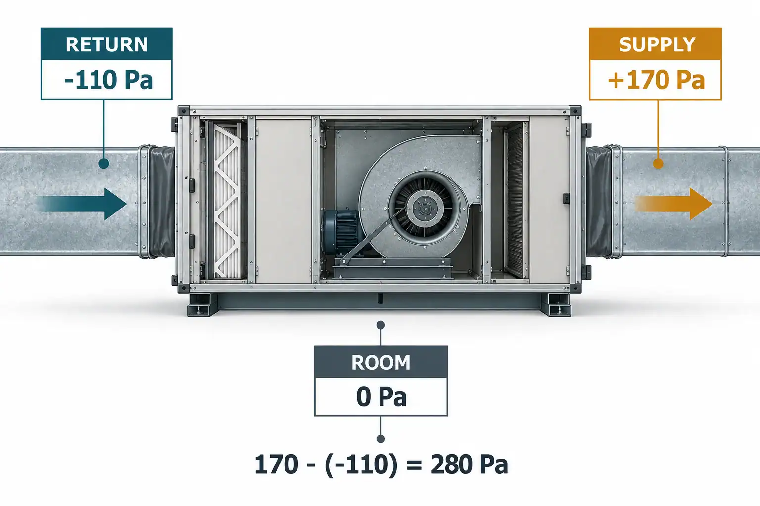
Consider a separate measurement across the manufacturer’s defined complete-unit boundary. Both readings use the same room reference:
- Return-side static pressure: -110 Pa.
- Supply-side static pressure: +170 Pa.
- Defined static difference: 170 – (-110) = 280 Pa.
The return pressure is below the room pressure, so its gauge reading is negative. It does not mean the absolute air pressure is below zero. Writing down the signs makes the calculation auditable.
Adding the magnitudes works in this example because the readings have opposite signs. It is not a universal calculation rule. If both readings were positive, such as +80 Pa and +170 Pa, the difference would be 90 Pa rather than 250 Pa. A differential manometer can report the difference directly; record which hose connects to each port.
The 280 Pa result becomes useful only after checking the equipment documentation. It may correspond to a specified external static measurement when the taps and included components match that definition. It is not automatically a bare-fan pressure requirement. Keep a sketch beside the readings so a second engineer can reproduce the boundary.
Convert Pa and inches of water without inventing a target
The conventional conversion is approximately:
1 in. w.g. = 249.1 Pa
Therefore, 0.5 in. w.g. is about 124.5 Pa, while 280 Pa is about 1.12 in. w.g. Inches of water gauge describe pressure; they are not a water-flow rate. Likewise, Pa and CFM cannot be converted into each other. One is pressure, the other is volumetric airflow.

There is no single acceptable static pressure for every air handler, cold-room evaporator or condenser. A value often quoted for residential equipment cannot replace the specified operating limit and blower table of a commercial unit. For example, the SVZ equipment listed on Trane’s M Series page has selectable settings of 0.30, 0.50 and 0.80 in. w.g. Those are model-specific settings, not a recommended range for another machine.
When comparing quotations, retain the original unit and show the conversion beside it. Also identify whether the number is a maximum permissible external pressure, a selected operating point, or a control setpoint. A maximum value does not establish the airflow available at every speed setting.
Measure at defined taps and a repeatable operating state
Begin with the manufacturer’s test locations and the measurement purpose. Checking a complete unit’s external static pressure, measuring a filter differential and characterizing a bare fan require different boundaries.
Before taking readings, zero the instrument at the intended reference, inspect the hoses, confirm the pressure range and orient the probes correctly. Fieldpiece’s measurement guidance describes these practical checks. Use approved test ports and qualified service procedures around coils, electrical parts and rotating equipment.

Record the operating state with the pressure. Useful fields include fan speed or control mode, filter identity and condition, doors and panels in their normal positions, coil wetness, damper positions and air temperature. For a refrigeration evaporator, add whether it is cooling, frosting, defrosting or recovering.
Choose measurement locations that reduce local disturbance, following the equipment or test method. An elbow, fan discharge or abrupt area change can make a single reading unrepresentative. If readings fluctuate, document the variation and investigate the location rather than averaging an unexplained number into apparent certainty.
Measure airflow separately with a suitable method or derive it only through a validated equipment relationship. A blower table can support an estimate when the model, speed, configuration and pressure basis match. A pressure reading from an unknown installation cannot supply the missing fan curve.
Define what external static pressure leaves outside the unit
External static pressure, often abbreviated ESP or TESP in equipment documentation, belongs to a specified equipment boundary. The word “total” in TESP does not turn a static-pressure measurement into fan total pressure.
A unit airflow table may already account for a particular internal coil, casing or filter configuration. Another table may exclude some accessories or require a correction. Read its notes before adding losses. Otherwise, the same coil can enter the calculation twice, or a filter can disappear from the budget.

For each quoted pressure, ask the supplier to return an inclusion list. It should name the coil, filter condition, electric heater, guard, silencer, transitions and other relevant parts. Identify additions installed outside the rated unit as well.
When coil and fan suppliers work independently, the inclusion list helps reconcile their quotations. The coil supplier may provide a pressure loss across its core. The fan supplier may provide a bare-fan curve. The equipment integrator must reconcile those outputs with the complete air path. The air-handler selection guide covers the wider equipment specification; this pressure record is one part of that decision.
Build a pressure budget for one complete air path
For a preliminary budget, identify each loss on a continuous path at one stated airflow. Components in series carry that path’s airflow, so their losses can be accounted for together. Parallel branches require a network or critical-path calculation; do not add the losses of every branch as though all air passes through each one.
The following example is hypothetical. It assumes 1.2 m³/s actual airflow, one declared density, and a consistent total-pressure-loss basis. The external allowance includes the relevant terminal and discharge conditions. There are no duplicated outlet or accessory allowances.
Item
Clean filter case
Loaded filter case
Item: Filter loss
Clean filter case: 80 Pa
Loaded filter case: 160 Pa
Item: Coil loss at the stated duty
Clean filter case: 100 Pa
Loaded filter case: 100 Pa
Item: Internal casing and fittings
Clean filter case: 80 Pa
Loaded filter case: 80 Pa
Item: External air-path allowance
Clean filter case: 220 Pa
Loaded filter case: 220 Pa
Item: Required fan total pressure
Clean filter case: 480 Pa
Loaded filter case: 560 Pa

The loaded-filter case adds 80 Pa at the required airflow. A fan that can deliver only 500 Pa at 1.2 m³/s has 20 Pa of arithmetic headroom for the clean case and a 60 Pa shortfall for the loaded case. That 20 Pa is not a recommended design margin. Uncertainty and installation allowances still need review.
Do not mix this total-pressure budget with an ESP rating without reconciling the definitions. Where areas or velocities change, a local static decrease is not necessarily identical to an irreversible loss: static pressure can recover as velocity decreases. Use the selected test and calculation method consistently.
Read the fan curve at the required airflow
A free-air airflow value is measured at a very different condition from airflow through a coil and filter. A maximum pressure value commonly occurs near very low flow. Selecting the largest number from each end of a catalog does not create a valid operating point.
At a fixed speed, the installed operating point follows the intersection of the fan’s pressure-flow curve and the system requirement. AMCA’s explanation of fan curves is useful for interpreting that relationship. Request the curve, selected point, pressure definition, air density, speed and permissible operating region together.

For many fixed-geometry air paths at roughly constant density, pressure loss can be approximated as proportional to airflow squared over a limited range. This is an estimate, not a universal coil rating law. Use supplier data for the required wet, fouled or frost condition, and account for changing dampers or control devices separately.
Density also matters. A curve rated at one density cannot be used unchanged for a materially different temperature or altitude. State whether airflow is actual or referenced to standard conditions. Cooling duty, air mass flow and fan pressure must describe the same operating state. The refrigeration fan guide provides the broader motor, geometry and application checks.
Compare two coils against the same fan curve
Suppose two proposed coils both satisfy a separately checked 25 kW thermal requirement at the same entering conditions and 1.2 m³/s actual airflow. The hypothetical fan provides 500 Pa fan total pressure at that airflow. All losses below use the same basis as the earlier budget.
Check at 1.2 m³/s
Coil A
Coil B
Check at 1.2 m³/s: Coil pressure loss
Coil A: 100 Pa
Coil B: 160 Pa
Check at 1.2 m³/s: Other clean-case losses
Coil A: 380 Pa
Coil B: 380 Pa
Check at 1.2 m³/s: Complete clean-case requirement
Coil A: 480 Pa
Coil B: 540 Pa
Check at 1.2 m³/s: Fan pressure minus requirement
Coil A: +20 Pa
Coil B: -40 Pa
Check at 1.2 m³/s: Requirement with loaded filter
Coil A: 560 Pa
Coil B: 620 Pa

Coil A clears the arithmetic clean-point check. Coil B does not. Neither pairing demonstrates the required loaded-filter airflow. A larger fan, lower resistance elsewhere, a revised coil geometry or a different maintenance limit needs evaluation before release.
Check the thermal assumption before accepting that comparison. A low-resistance coil that fails cooling capacity is not an acceptable substitute. Nor can the 25 kW value be retained automatically if the actual operating airflow drops below 1.2 m³/s. Request a new thermal rating at the resulting point, including sensible and latent outputs when moisture removal matters.
For a new design, compare face area, depth, fin pitch and cabinet space together. The commercial coil sizing guide explains those geometry inputs. A pressure budget helps identify the constraint; it does not determine the final construction by itself.
Keep dry, wet, dirty and frost conditions distinct
A pressure-loss value should identify the coil state. Condensate, deposited dirt and frost change the air passages and surface conditions differently. Their effects depend on geometry and operation, so a single universal percentage increase would be misleading.
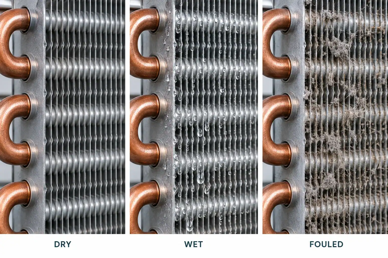
For a cooling coil expected to dehumidify, request the wet operating rating at the relevant air state. For a condenser in a dusty cabinet, define the filter or screen condition and cleaning access. For a low-temperature evaporator, document the frost condition at which airflow and cooling must remain acceptable, plus the defrost control basis.
Compare pressure loss at matched airflow and density. A blocked coil can have a lower measured differential than expected if the fan’s airflow has already collapsed. A reduced reading after a change is therefore insufficient evidence that the air path improved.
Keep the maintenance acceptance condition measurable. Examples include a specified filter differential, a defined inspection state or a validated airflow limit. Choose the criterion with the equipment designer; an arbitrary cleaning interval does not verify the fan’s remaining capability.
Check inlet and outlet geometry before increasing fan speed
A fan can meet its laboratory curve and perform poorly inside an actual cabinet. A close obstruction, tight inlet elbow, abrupt transition or unfavorable discharge can disturb the flow. AMCA’s system-effect article explains why installed geometry belongs in the selection review.

An OEM review should show the coil-to-fan arrangement, inlet clearance, guard, shroud, discharge and service panels on the same drawing revision. A generic curve cannot establish the loss created by an untested cabinet detail.
Separate the possible causes of a shortfall. If the component ratings are correct but the assembled unit misses airflow, inspect installation effects and leakage as well as the fan command. If a component’s measured loss differs substantially from its rating at matched conditions, resolve that discrepancy before changing the motor.
Increasing speed may restore airflow within the fan’s permitted operating range, but it also changes power, sound and mechanical duty. Review motor loading and control limits. Treat a revised speed as a new operating point requiring verification.
Interpret pressure changes with the fan control mode
At fixed speed, added system resistance commonly shifts the operating point toward lower airflow. A controller that maintains airflow may increase speed or power until it reaches a limit. A constant-pressure controller instead regulates the pressure at its sensor location. These responses are different, even when the equipment uses the same motor technology.

An EC motor label alone does not establish constant-airflow control or unlimited pressure capability. Record the actual control algorithm, setpoint, sensor position and maximum speed. Pressure upstream of a loaded filter does not describe every downstream branch.
For an illustrative power check, moving 1.2 m³/s against 560 Pa fan total pressure transfers 672 W to the air. At an assumed fan total efficiency of 0.55, required shaft power is about 1.22 kW. Electrical input is higher when motor and drive losses are included. These assumed values are not Domi product data or an energy prediction.
Use the same efficiency definition as the pressure basis. Dividing total air power by a static efficiency without reconciliation produces a misleading result. Obtain the supplier’s electrical input at the selected point when comparing operating cost.
Request an airflow and pressure record the supplier can check
Give the supplier enough information to reproduce the duty point. Send the required actual airflow, temperature or density basis, altitude where relevant, thermal duty and entering air/fluid conditions. Attach the air-path drawing with its pressure boundaries marked.
Include the following records:
- Component identities and losses, with the applicable airflow and clean, wet, loaded or frost condition.
- The fan curve and selected speed or control mode, including whether the curve uses fan static or fan total pressure.
- The unit-rating inclusion list and any accessory corrections.
- Coil envelope, fin arrangement, mounting, connections and available service clearance.
- Acceptance limits for airflow, thermal capacity, pressure loss, power and sound, with the proposed verification method.
- Drawing revision, unresolved assumptions and the person responsible for approving each open item.

Ask the supplier to separate calculated ratings from measured results. A pressure or leak test on the refrigerant circuit does not establish air-side resistance. A photograph of a coil does not establish either thermal capacity or a fan curve.
For sample approval, agree on the assembled configuration, sensor positions, operating state and reporting basis before the test. Domi’s testing and validation support page describes the relevant review areas. Confirm the method and available evidence for the specific project rather than assuming that every test or certification applies.
Frequently asked questions
Is static pressure the same as CFM?
No. Static pressure measures pressure; CFM measures volumetric airflow. Their relationship depends on the fan, speed, air density, system resistance and control mode. A validated fan or equipment curve can relate them at a defined condition.
Can moving air have static pressure?
Yes. Static pressure is a local fluid property, so it can exist in moving air. Velocity pressure accounts for the bulk motion. For the low-speed approximation used here, total pressure is the sum of static and velocity pressure.
How do you calculate HVAC static pressure?
Subtract the signed upstream static reading from the downstream reading across the defined boundary. With +170 Pa supply and -110 Pa return, the difference is 280 Pa. Check that both readings use the same reference and match the manufacturer’s measurement locations.
What is a good external static pressure?
Use the specific equipment’s airflow table, rated configuration and permissible limits. A common residential value is not a universal commercial design target. Verify the required airflow at the selected setting, including the relevant coil and filter condition.
Is fan static pressure the same as external static pressure?
They describe different boundaries and definitions. Fan static pressure is fan total pressure less outlet velocity pressure. Equipment ESP uses the unit boundary and rating instructions. Reconcile the included components before comparing the numbers.
Does a high pressure reading prove the coil is blocked?
No. Filters, ducts, guards, dampers, installation effects and control settings can also affect the result. Compare component differentials at known airflow and density, inspect the air path and confirm the measurement locations before assigning the cause.
Can a higher-pressure fan solve poor cooling?
It may help if insufficient airflow is the cause and the selected fan can operate safely at the required point. It cannot correct an undersized thermal coil, refrigerant fault or unsuitable control sequence. Recheck airflow, thermal output, power and sound together.
What does static water pressure mean?
In a water-system discussion it commonly means pressure under a no-flow condition, often measured relative to atmosphere. That is a different application from this HVAC air-path guide. Do not transfer duct pressure targets, fan curves or airflow formulas to a water circuit.
Approve the coil and fan on one documented operating basis
Before releasing an order, confirm that airflow, pressure definition, component boundary and operating condition agree across the fan curve, coil rating and unit specification. Keep the loaded or end-of-cycle case visible alongside the clean nominal point. If a required value is missing, return the assumption for review before treating the selection as approved.
Domi’s custom coil fabrication service accepts drawings, samples and parameter sheets for review. Send the pressure budget with the coil envelope, thermal requirement and fan information so the team can identify missing inputs and discuss a project-specific sample and validation plan.
Related refrigeration resources
- Commercial refrigeration coil sizing and face velocity
- Refrigeration fans, motors and duty-point selection
- Air-handler specification and component boundaries
- Sensible heat ratio and separate moisture-removal checks
- Condenser dust protection and screen pressure allowance
- Custom coil fabrication from drawings or samples