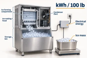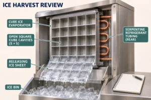

The heat transfer coefficient describes heat transfer per unit area and temperature difference. A convection coefficient, h, applies between a surface and a fluid. An overall coefficient, U, combines the resistances along a complete heat-transfer path. Both commonly use W/(m²·K). Conductance, UA, uses W/K. For a coil purchase, compare the same area basis and operating conditions before judging which rating is better.
A supplier may quote a large coefficient for a surface or flow condition that differs from your specification. This guide helps OEM engineers and technical buyers check that difference before changing a refrigeration coil. The original AI-generated illustrations explain concepts; they do not document Domi factory equipment or measured performance. Every numerical example below is hypothetical.
Jump to: h versus U versus UA, area basis, calculation, measurement, restocking example, or quotation checklist.
What does a heat transfer coefficient mean?
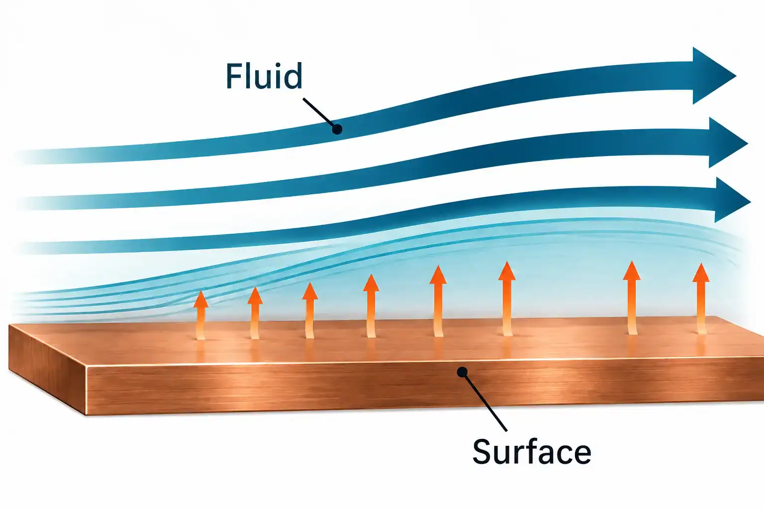
For convection, a common engineering expression is Q = h × A × ΔT, where Q is heat-transfer rate in watts, A is the participating surface area in square meters, and ΔT is the temperature difference between the surface and the fluid reference temperature. Rearranging gives h = Q / (A × ΔT). The sign convention should follow the chosen direction of heat flow.
The Ansys lesson on defining the heat transfer coefficient explains the importance of the reference temperature. A wall temperature and a bulk-fluid temperature answer a different question from two fluid inlet temperatures. The coefficient also depends on the flow situation; it is not a fixed property of copper, aluminum or air.
For example, suppose a uniformly heated surface transfers 1,500 W to air over 2 m², with an appropriate mean surface-to-air difference of 30 K. The inferred average h is 1,500 / (2 × 30) = 25 W/(m²·K). That result belongs to the assumed test boundary. It does not establish the overall coefficient of a complete refrigeration coil.
What is the difference between h, U and UA?
Each quantity has a different boundary. A film coefficient can help diagnose one side of a heat exchanger. An overall coefficient combines the path between the fluids. Conductance combines the overall coefficient with its declared area.
Quantity
Meaning
What a buyer must verify
Quantity: h, W/(m²·K)
Meaning: Convection between a surface and a fluid
What a buyer must verify: Which fluid, reference temperature, geometry and flow condition?
Quantity: U, W/(m²·K)
Meaning: Overall heat transfer normalized to a stated area
What a buyer must verify: Which surface area and which resistances are included?
Quantity: UA, W/K
Meaning: Overall thermal conductance
What a buyer must verify: Is U multiplied by its matching area, at the same rating condition?
Quantity: Q, W or kW
Meaning: Heat-transfer rate at the operating point
What a buyer must verify: Which temperatures, flows, humidity and refrigerant state apply?
UA is useful when two suppliers use different area conventions, provided each has paired U with the correct A and represented the same physical boundary. It still needs a rating point. It is not a universal constant that can be carried unchanged through every fan speed, frost state or refrigerant condition.
For a purchasing decision, start with required duty and allowable pressure losses. Use h, U and UA to explain or check the proposed rating. Our commercial refrigeration coil sizing guide covers the wider load and geometry inputs.

How do thermal resistances determine U?
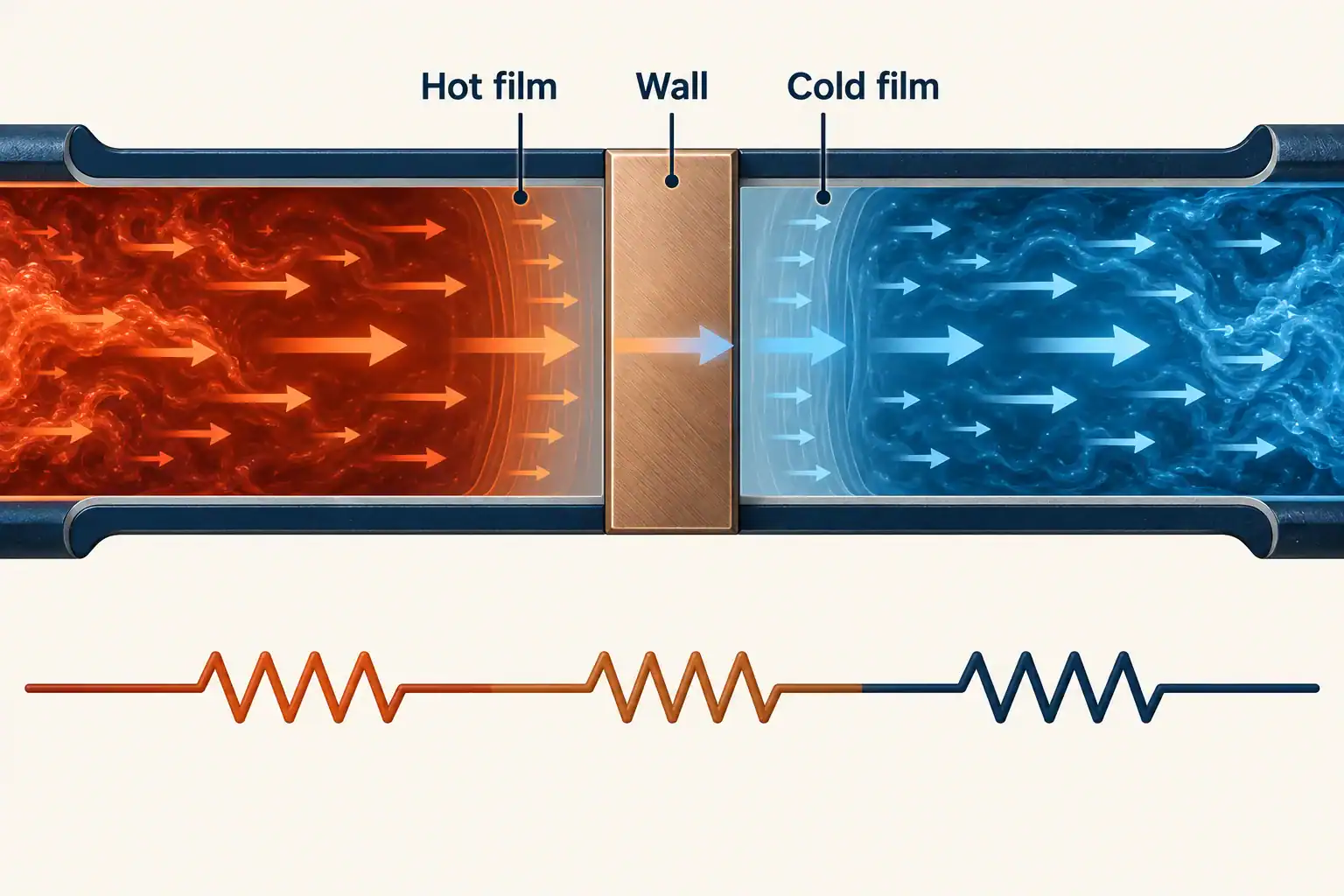
A simple flat-wall model with one area throughout gives 1/U = 1/h₁ + δ/k + 1/h₂. Here δ is wall thickness and k is the wall material’s thermal conductivity. Fouling terms can be added on a consistent area basis. This flat-wall expression should not be copied unchanged into a finned-tube rating.
For a cylindrical tube, the inside and outside areas differ, and the wall resistance involves the diameter ratio. MIT’s heat exchanger notes derive that series-resistance relationship. Fins add another requirement: the extended surface cannot automatically be treated as if every point were at the tube temperature.
Ask which resistance limits the design. If a model attributes most resistance to the air side, ask the supplier to compare an air-side change with a tube-side change at the same duty. Request the predicted change in capacity and pressure drop, rather than accepting a claim that a material upgrade alone solves the thermal problem.
Why can two U values describe the same coil?
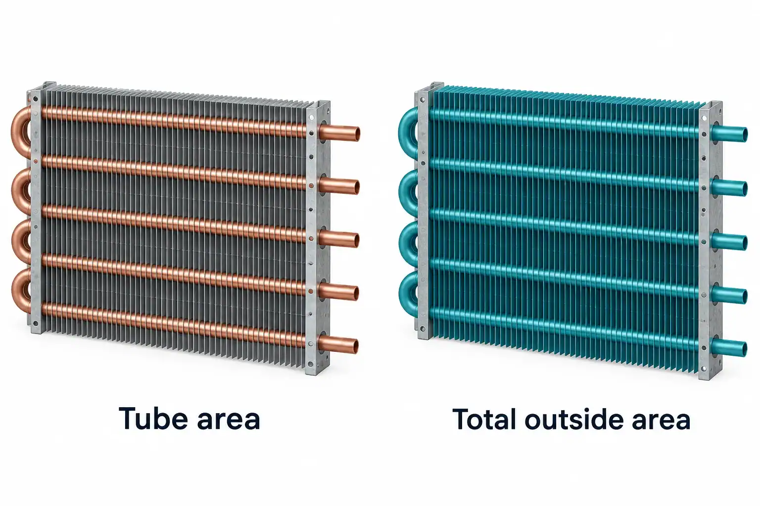
A higher quoted U can result from using a smaller reference area. The same coil may be reported using inside tube area, outside tube area or total external fin-and-tube area. Those numbers are not interchangeable.
Consider one hypothetical coil with UA = 900 W/K. On an area basis of 40 m², its reported U is 22.5 W/(m²·K). On a different reference area of 2 m², U becomes 450 W/(m²·K). Multiplying each value by its matching area gives the same 900 W/K. Nothing about the physical coil improved.
This example is an area conversion, not a comparison of bare and finned coil performance. Ask each supplier to mark the reference surface on a drawing and explain how it was calculated. If fins are included, establish whether the stated U already incorporates fin efficiency and contact effects. Applying those corrections twice creates a different error.
When the area definition is missing, return the rating for clarification before ranking suppliers. Sorting the U column without checking area can put the wrong proposal first.
How do fins affect the coefficient and useful surface area?
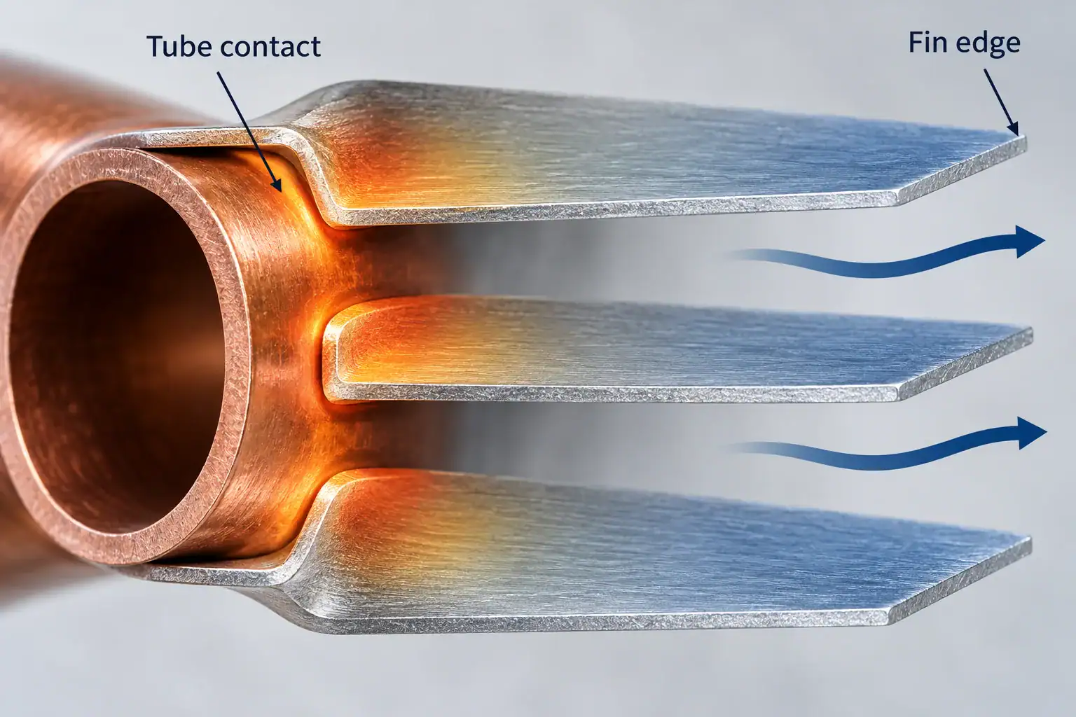
Fins add air-side surface, but their temperature varies with distance from the tube contact. MIT’s fin analysis describes conduction along a fin while convection transfers heat between that fin and the surrounding fluid. A design therefore needs more than a geometric fin-area total.
One useful notation for the effective external area is A_effective = A_bare + η_f × A_fin, where η_f is fin efficiency under the chosen model. An equivalent overall-surface-efficiency formulation may be used. Confirm the rating method rather than assuming that all suppliers use the same notation.
For an OEM review, request the fin geometry revision, material and thickness, collar/contact arrangement, and the method used to account for surface efficiency. Link those items to the sample being tested. If production changes a fin pitch or tube expansion process, the old drawing and old performance result may no longer describe the delivered part.
Our guide to how fins help a radiator explains the surface-area role in more detail. Here the purchasing issue is whether the coefficient and area in the quotation describe the same build.
Which operating conditions change h?
A coefficient estimate must match the fluid and flow geometry. Ansys’s HTC calculator documentation relates h to the Nusselt number, fluid thermal conductivity and a characteristic length. That relationship makes the selected correlation and its range part of the calculation evidence.
For a coil rating, ask which correlation or validated software method was used, where fluid properties were evaluated, and whether the case lies within the method’s range. A tube-flow correlation and an external fin-bank correlation represent different geometries. The characteristic length needs its definition, not just a number.
Two-phase refrigerant regions need particular care. The Purdue heat-transfer lecture notes that boiling or condensing coefficients can vary substantially through the flow. Ask whether the supplier segments the coil into relevant regions and how it handles distribution, superheat or subcooling zones. A single average coefficient should come with the assumptions that make it meaningful.
For purchasing, a small operating-point schedule is often more useful than one nominal coefficient: design duty, high ambient or peak load, and a relevant minimum-load case. The supplier should identify any case it has calculated but not tested.

How do you calculate an overall heat transfer coefficient?
For a suitable steady heat-exchanger model, Q = U × A × F × ΔT_lm. ΔT_lm is the log mean temperature difference and F is a correction factor when required by the arrangement. Use a model appropriate to the exchanger; F is not a tuning factor to make a quotation pass.
For a hypothetical dry sensible-duty calculation, assume Q = 6,000 W, A = 20 m², F = 1 and ΔT_lm = 15 K. Then U = 6,000 / (20 × 1 × 15) = 20 W/(m²·K) and UA = 400 W/K. The calculation is internally consistent, but its validity still depends on the area definition, flow arrangement and measured or predicted temperatures.
For positive terminal differences, ΔT_lm = (ΔT₁ − ΔT₂) / ln(ΔT₁ / ΔT₂). The equal-difference limit is that common temperature difference. Crossflow and multipass arrangements need their appropriate treatment. The heat-duty and temperature-program approach is set out in Alfa Laval’s heat-transfer theory guide.
Before using this calculation for an evaporator, establish whether the duty is dry sensible cooling, dehumidification, frosting or a combination. A wet air-side duty requires a method that includes moisture removal. Do not infer total capacity from dry-bulb temperature change alone when the test also removes water.
How do fouling and frost affect a rating comparison?
Separate a clean calculation from a service-condition requirement. Alfa Laval’s guide distinguishes clean and design coefficients and includes fouling resistance in its thermal model. Its plate-exchanger values are not default values for a beverage-cooler coil.
As a sensitivity example on one unchanged area basis, let U_clean = 20 W/(m²·K) and assume an added thermal resistance of 0.005 m²·K/W. Then 1/U_dirty = 1/20 + 0.005, giving approximately 18.18 W/(m²·K). With area, flow and driving temperature difference held constant, the modeled heat transfer is about 9.1% lower. The resistance is an invented input for this example, not a recommended allowance.
Real dust or frost can also alter airflow, so this simple resistance-only result cannot predict the complete cabinet response. Define the contamination or frost condition, operating interval and cleaning/defrost sequence for the sample comparison. The dust-proof condenser design guide addresses the related retail installation questions.

Is a higher heat transfer coefficient always better?
A larger coefficient can be useful if it improves the required duty within the buyer’s other limits. It should be evaluated alongside airflow or fluid flow, pressure loss, electrical input, sound, envelope and service access. Ask what changed to obtain it.
For example, a proposal may assume a higher air volume than the installed fan can deliver through the cabinet. The coil calculation may be valid at that assumed flow while the assembled cabinet operates elsewhere. Request the proposed fan operating point and the complete air-path resistance basis, including guards, filters or louvers that belong to the installation.
Compare alternatives at a shared boundary: the same fan control, the same permitted pressure drop, or the same electrical input, whichever matches the purchasing requirement. Record the chosen boundary in the request. Otherwise, one supplier may optimize capacity while another optimizes power, and the two results will appear contradictory.
How should a supplier measure and report performance?
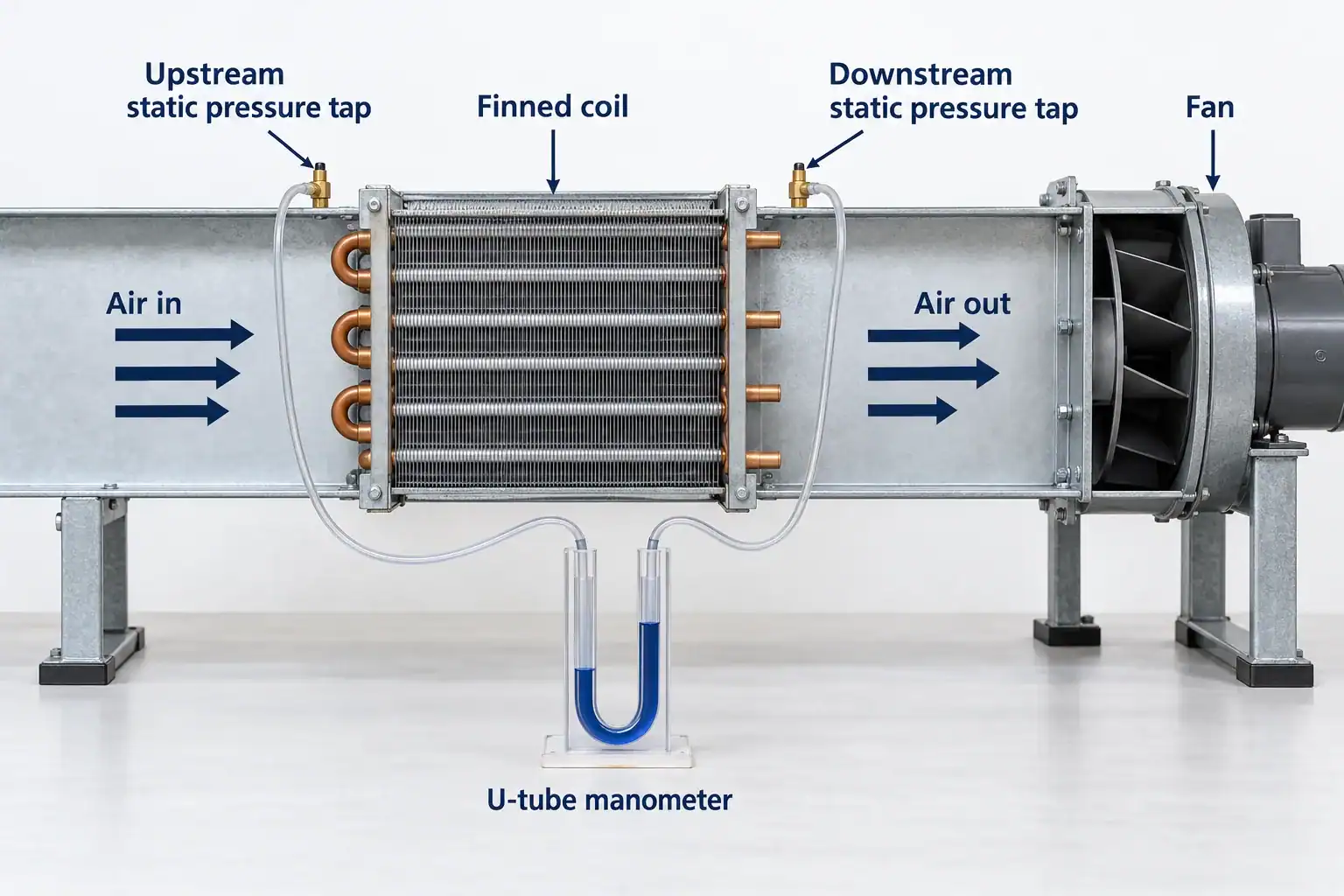
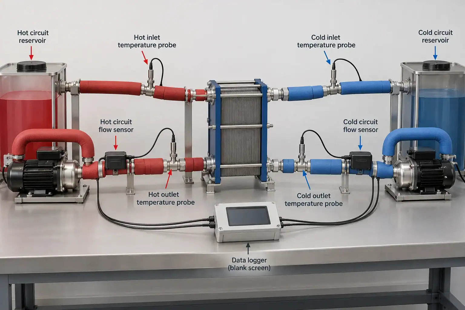
Request a test plan before releasing the sample. It should identify the drawing revision, sensor locations, flow measurement method, operating conditions, stabilization rule, sampling interval and acceptance limits. Ask how measurement uncertainty affects the claimed difference between designs.
For an appropriate single-phase stream, a heat balance can use Q = mass flow × specific heat × temperature change. The report must state the fluid composition and property basis. If a second-side balance is available, request both values and the agreed energy-balance tolerance. Unexplained disagreement should be investigated rather than averaged away.
Ask the report author to distinguish measured inputs, calculated results and assumptions. If U is back-calculated, it should show Q, A and the driving temperature difference. If a simulation supplies U, the result should be labelled as a prediction with its validation basis. The word “tested” should refer to the particular sample, method and conditions.
For a small measured temperature difference, ask whether the temperature instruments can resolve the difference being claimed. A capacity increase smaller than the declared uncertainty is weak evidence for choosing a more expensive coil. Domi’s testing laboratory page provides a starting point for discussing the required validation scope.
What does the coefficient tell you about beverage cooler pull-down time?
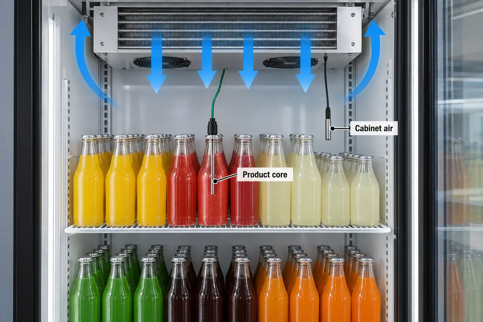
A coil coefficient alone cannot establish beverage cooler pull-down time. After restocking, the required result is a product-temperature recovery profile under a stated loading and door-use procedure. The air sensor can recover before the drink in the slowest-cooling position reaches the target.
Use an energy estimate to frame the requirement. Assume a hypothetical replenishment of 90 kg of beverage, an assumed specific heat of 4.0 kJ/(kg·K), and a temperature reduction of 18 K. The product energy is 90 × 4.0 × 18 = 6,480 kJ. Removing it in one hour requires an average 1.8 kW for that product alone. If other heat gains average an assumed 0.6 kW, the arithmetic total is 2.4 kW.
This is an average-duty estimate, not proof that a 2.4 kW evaporator cools every bottle in an hour. Packaging, shelf arrangement, local air circulation, changing temperature differences, compressor operation and door events still need to be represented. Larger UA may help the coil under stated conditions, but it cannot correct every bottleneck between cabinet air and the beverage core.
For an OEM comparison, fix beverage mass, bottle size, initial product temperature, ambient temperature and humidity, stocking pattern, door schedule and control settings. Place product-core probes at agreed representative and difficult locations, alongside separate air probes. State when timing begins and what constitutes completion. Keep startup from an empty warm cabinet separate from recovery after replenishment.
If the complaint is slow recovery, request those traces before increasing coil surface. They help distinguish an equipment-capacity question from a product-airflow or test-procedure question.
What should you request in a coil quotation?
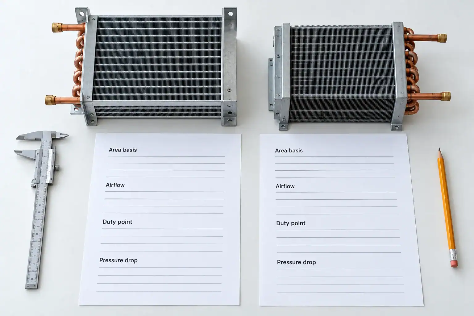
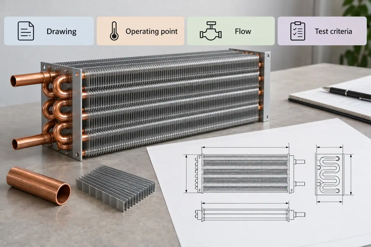
Send a rating sheet and drawing with matching revision references. Ask the supplier to flag missing inputs and return assumptions explicitly, so procurement can compare proposals without reconstructing each model.
Quotation field
Buyer input
Supplier response to request
Quotation field: Duty and temperatures
Buyer input: Required capacity and operating-point schedule
Supplier response to request: Rated duty for each case, with calculation/test status
Quotation field: Coefficient and area
Buyer input: Preferred reporting boundary
Supplier response to request: h or U definition, area basis, matching UA and included corrections
Quotation field: Flow and pressure loss
Buyer input: Air/fluid flow and allowable losses
Supplier response to request: Operating point, predicted losses and installed-path assumptions
Quotation field: Geometry and service
Buyer input: Drawing revision, envelope, access and environment
Supplier response to request: Proposed materials, circuiting, fin arrangement and exclusions
Quotation field: Validation and supply
Buyer input: Acceptance procedure, sample and quantity requirements
Supplier response to request: Test scope, deviations, sample plan, lead time and commercial terms
Reject a coefficient-only comparison when the area basis is absent, the fluid or refrigerant state differs, one rating is wet and another dry, or the duty points do not match. Ask for a rerating at the shared conditions. If a supplier cannot provide it, keep the performance comparison unresolved.
Domi’s custom coil fabrication page and engineering capabilities describe the relevant routes for a drawing and application review. Send the current rating, required duty points, available envelope and the question you need the sample to answer. Confirm project-specific scope and acceptance criteria with the technical team.
Frequently asked questions
What are the units of heat transfer coefficient?
The usual SI units for h and U are W/(m²·K). A temperature difference of 1 K has the same magnitude as 1°C. UA uses W/K because the area has already been multiplied into the coefficient. Heat-transfer rate Q uses W or kW.
Is heat transfer coefficient a material property?
No. A convection coefficient depends on the fluid, flow, geometry and chosen reference temperature. Thermal conductivity k is a material property used in a conduction model. An overall coefficient U combines the relevant path and operating conditions, so identifying the wall material does not determine U by itself.
What is a good heat transfer coefficient for a refrigeration coil?
There is no single value that qualifies every coil. First identify whether the number is h or U, its area basis, refrigerant or fluid condition, airflow, surface condition and rating method. Judge the proposal against required capacity, pressure losses and validation criteria at your operating points.
Can two different U values represent equal performance?
Yes. Different reference areas can produce different U values for the same conductance. In the example above, 22.5 × 40 and 450 × 2 both give 900 W/K. Reconcile the boundaries and conditions before using that equality to compare separate physical products.
Does adding more fins always improve a coil?
Fin count alone cannot establish the outcome. Ask the supplier to rate the changed geometry at the installed flow condition and report pressure drop, surface-efficiency treatment and relevant cleaning or frost constraints. Compare the complete proposal against the original duty and service requirements.
Can I calculate U from a catalog capacity?
Only if the capacity, area definition and appropriate driving temperature difference are available for the same rating point. Check the flow arrangement, correction method and dry/wet basis. A nominal capacity with missing rating conditions is insufficient for a defensible back-calculation.
Does a higher UA guarantee faster beverage cooling?
No. UA describes the coil at stated conditions. Beverage-core recovery also depends on the load, packaging, cabinet circulation and system operation. Use a controlled restocking test with separate air and product-core measurements to verify the time requirement.
What should an OEM send for a coefficient review?
Send the drawing revision, existing rating sheet, surface-area definition, fluid or refrigerant, operating temperatures, flow rates, pressure-drop limits and available test results. Include the intended change and acceptance criterion, such as a specified duty point or a reproducible product-temperature recovery requirement.