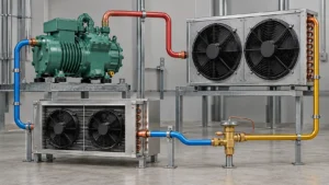
Ice machine condenser coil selection should start with heat rejection across the complete freeze, harvest, recovery and standby sequence, then use the actual condenser entering-air or entering-water condition. The coil, fan, water circuit or remote line set, refrigerant, controls, fouling allowance, cabinet space and service access need to work as one system. Ice output and compressor horsepower alone are not a selection basis.
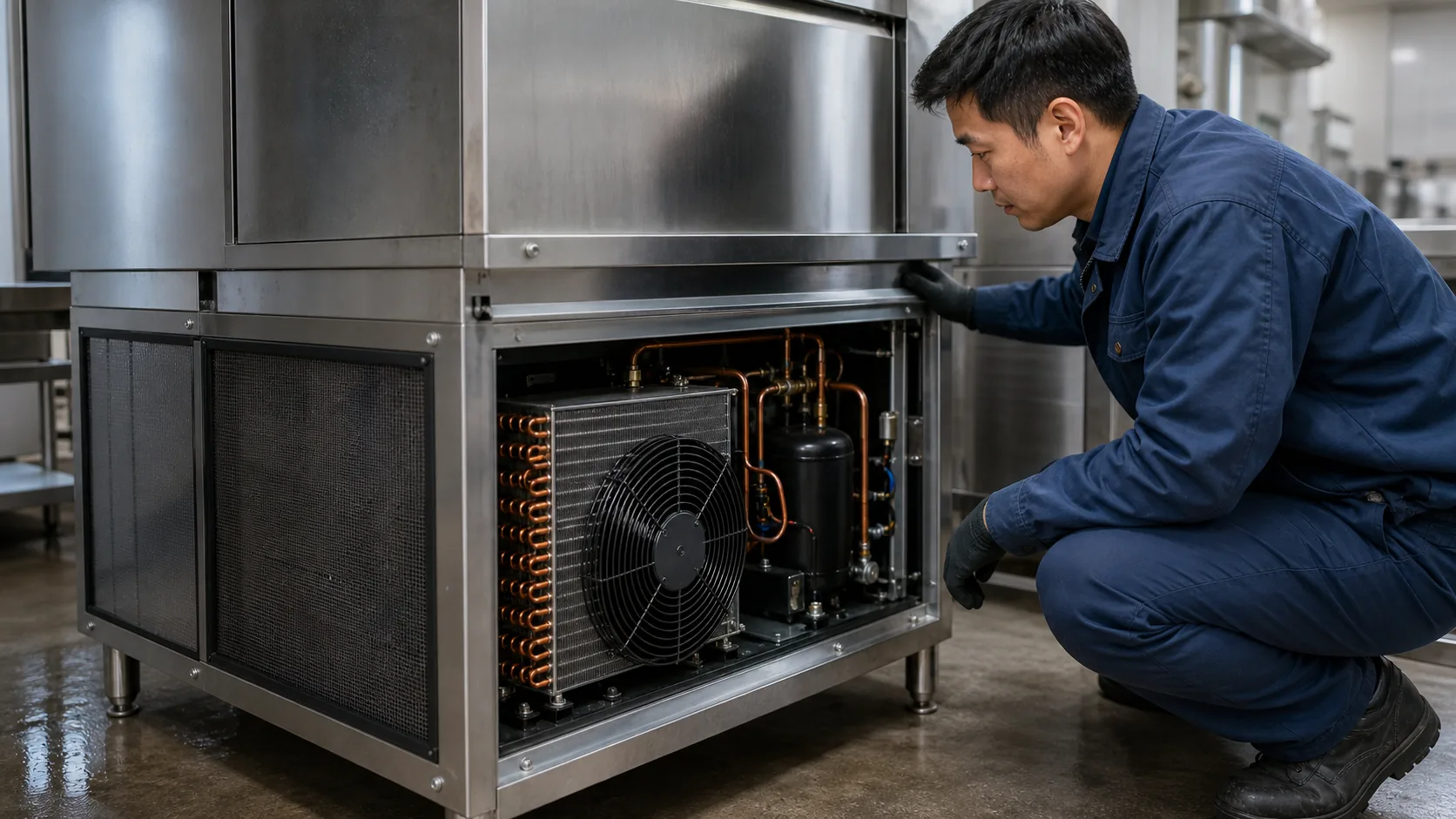
A commercial ice machine has two heat-transfer jobs. The evaporator removes heat from water so ice can form. The condenser rejects that absorbed heat plus compressor input to room air, condenser water or a remote outdoor location. Treating either component as a stand-alone catalog item can leave the machine short of production on a hot day, difficult to clean in a kitchen or unstable during harvest.
This guide is for OEM engineers, sourcing teams and equipment suppliers preparing a new design, replacement project or supplier comparison. It explains the project inputs that control an ice machine condenser, the choices that belong to the complete appliance and the data a coil supplier should return. It does not replace a refrigeration-system design review, code evaluation or complete-machine certification.
Start with the ice-machine architecture, not the coil face size
The U.S. Department of Energy defines an automatic commercial ice maker as an integrated assembly that includes the condensing unit and ice-making section. In an RFQ, that definition keeps the component and machine boundaries clear. A coil manufacturer may supply one part, but condenser performance depends on the rest of the assembly.
Begin with a one-page system boundary. Show the ice-making section, compressor, condenser, metering device, fan or condenser-water circuit, receiver if used, line set, controls and installation heat sink. Mark which parts are fixed, which parts may change and which party is responsible for each interface.
Do not start by copying the old coil face width and height. Those dimensions prove only that a part may fit the opening. They say nothing about heat-rejection duty, entering-air temperature, pressure drop, refrigerant distribution, fan operating point or the effect of a dirty filter.
Batch and continuous machines create different time histories
Commercial machines can make ice in alternating batches or in a continuous process. ENERGY STAR’s commercial ice maker overview distinguishes batch-type equipment from continuous flake and nugget machines. The distinction changes the load history.
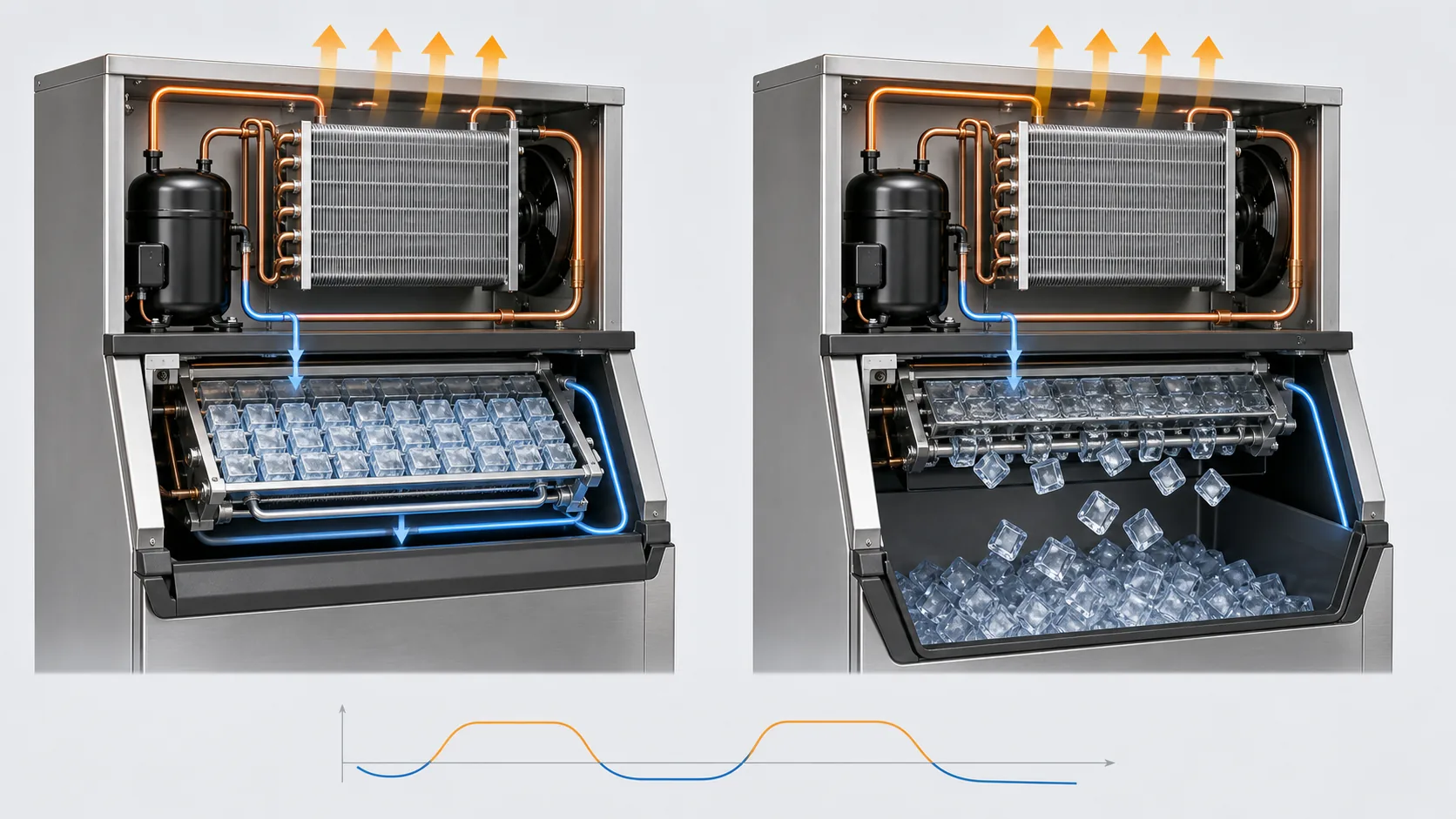
A batch machine has a freeze period followed by a harvest event. Refrigerant conditions, water flow, control state and compressor loading can change during that sequence. A continuous machine may reach a more stable average, but auger load, water feed and product discharge still affect operation. The condenser must support the machine’s actual time history, not an assumed flat load.
Self-contained and split systems move the design boundary
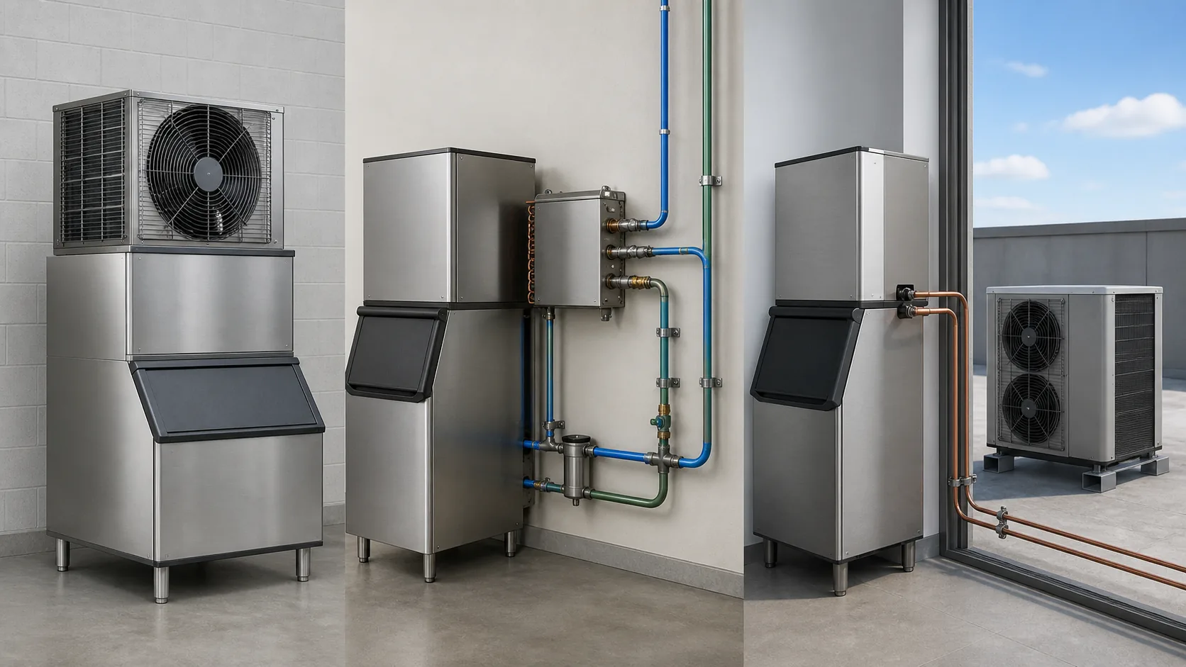
In a self-contained air-cooled machine, the condenser coil, fan and intake path share the cabinet with the ice-making section. The surrounding room becomes the heat sink. A water-cooled machine transfers heat to a condenser-water circuit. A remote arrangement moves the condenser, or the complete condensing unit, away from the ice-making head.
Record that distinction before sizing. A remote condenser alone still depends on the machine compressor, refrigerant charge, controls and line-set rules. A remote condensing unit moves a different set of components and creates a different responsibility split.
Build the condenser heat-rejection basis from operating states
For a refrigeration cycle, condenser heat rejection is approximately the evaporator load plus compressor power. Add any other heat that reaches the same condenser boundary. The useful expression is simple:
Q condenser = Q evaporator + compressor input + included auxiliary heat
The difficult part is defining each term at the correct state. Ice production in pounds per day or kilograms per day is an output target, not an instantaneous condenser duty. The same daily output can come from different cycle lengths, ice thicknesses, harvest methods, water temperatures and control strategies.
Use compressor performance data or measured prototype data where available. If the machine is still conceptual, keep the assumptions visible and return to them after the compressor, evaporator and cycle controls are selected.
Freeze, harvest, recovery and standby are separate states
Build a state matrix before requesting a coil selection:
- During freeze, record evaporator load, suction and discharge conditions, compressor input, condenser entering condition and fan or water flow.
- During harvest, record whether the compressor continues, whether hot gas or another heat source is used, how long the event lasts and how the condenser and fan are controlled.
- During recovery after a warm start, cleaning cycle or long shutdown, record the temporary load and time needed to return to stable ice production.
- During standby or bin-full operation, define which fans, pumps, heaters and controls remain active.
The design point may be the highest sustained heat rejection, the most difficult high-ambient state or a control-stability condition. It is not automatically the largest number in a sales table.
State every rating and installation condition
AHRI 810 covers test requirements, ratings, published data and nameplate information for automatic commercial ice makers. A supplier selection should preserve the same discipline even when the component itself is custom.
For every duty, state refrigerant, saturated condensing and evaporating conditions, superheat or suction condition where relevant, subcooling target, mass flow or compressor model, entering-air dry-bulb or entering-water temperature, airflow or water flow, altitude if material, and allowable pressure drops. Mark values as measured, calculated, assumed or required.
Without this basis, two suppliers can return different coil sizes and both appear reasonable because they solved different problems.
Choose air-cooled, water-cooled or remote condensing
The cooling method determines where the rejected heat goes and which utilities, controls and maintenance tasks the site inherits. Make that choice before optimizing a fin pattern.
| Arrangement | Heat sink | Useful when | Inputs that must be confirmed | Main integration risk |
|---|---|---|---|---|
| Self-contained air-cooled | Air at the machine | The room can accept heat and noise, and the cabinet has a clean, open air path | Entering air, airflow, fan curve, grille loss, clearance, fouling | Warm exhaust recirculates or the intake loads with dust and grease |
| Water-cooled | Condenser-water circuit | A suitable water source or recirculating loop is available and permitted | Entering water, flow, pressure, water quality, scale control, discharge path | Water use, scale or unstable regulating-valve behavior is omitted from the selection |
| Remote air-cooled condenser | Outdoor or remote-room air | Indoor heat and sound must move away from the ice maker | Matched equipment, line route, elevation, ambient, charge, fan control, weather exposure | A generic remote coil is paired without checking the approved system envelope |
| Remote condensing unit | Remote air plus remote compressor package | The project needs a broader split-system architecture | Complete condensing-unit data, controls, piping, oil return and service boundary | Responsibilities between ice-making section and condensing package are unclear |
Self-contained air-cooled arrangements
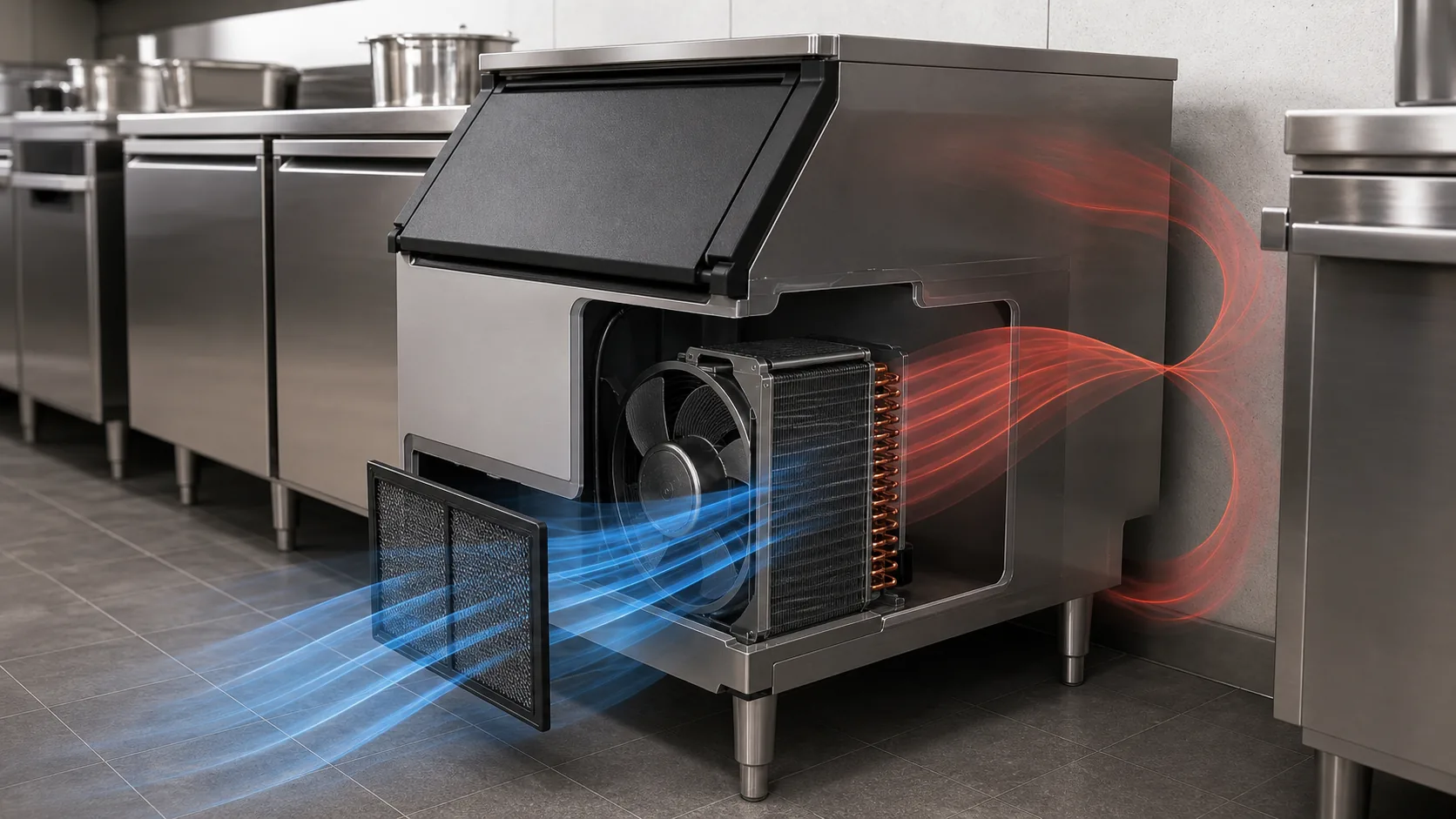
Air cooling avoids a condenser-water connection, but it puts the entire airside problem inside the installation. Confirm the temperature at the condenser intake rather than relying on the thermostat setting across the room. The machine may sit under a counter, beside a cooking appliance or against a wall that traps its own discharge air.
Select the coil and fan together. A clean-coil airflow value is incomplete without the fan curve, grille and filter losses, cabinet resistance and an allowance for expected fouling. A deeper coil may provide more area but also raise air pressure drop and cleaning difficulty.
Water-cooled arrangements
A water-cooled ice machine may use a compact refrigerant-to-water condenser rather than a finned air coil. Keep the selection language honest: the project is choosing a condenser heat exchanger and water circuit, even if the queue keyword uses “coil.”
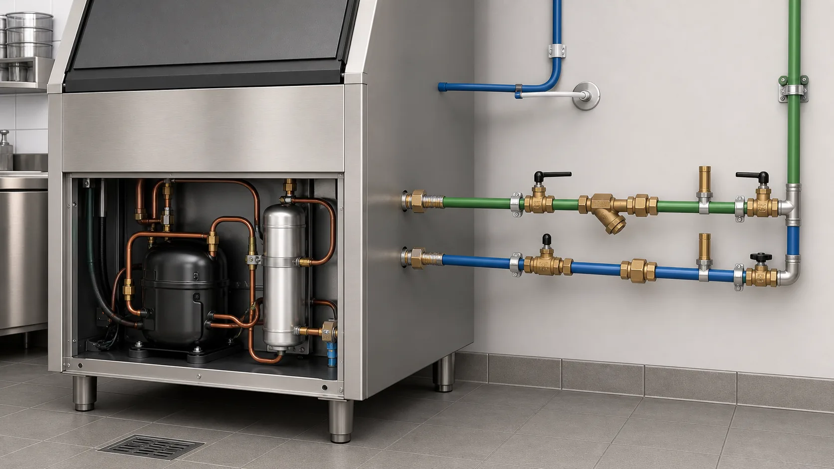
Confirm whether the water is once-through or recirculated, the permitted flow and discharge arrangement, entering-water range, water quality, scale tendency, control valve and cleaning method. Local water rules and utility costs can make an otherwise workable design unsuitable. Do not assume potable ice-making water and condenser water share a circuit.
Remote air-cooled and remote condensing-unit arrangements
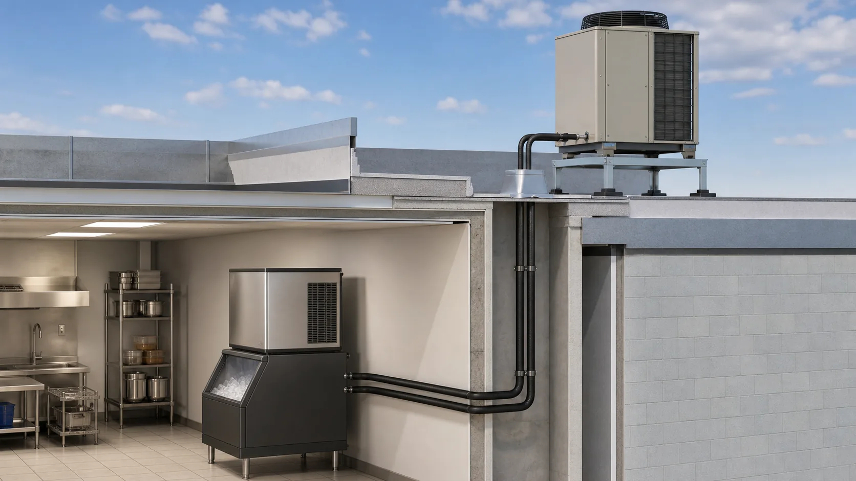
Remote equipment can move heat and sound out of the occupied space, but it adds refrigerant piping, charge, elevation, weather and control limits. Manufacturer documents show why these details are model-specific. The Manitowoc installation manual pairs particular ice-machine heads, condensers and line sets. The Hoshizaki SRK-15J page likewise lists a compatible ice maker, line kits, operating limits and clearance for that product.
Use such documents as evidence that the interfaces matter, not as universal limits for a custom project. A different refrigerant, compressor, head-pressure control, line diameter or vertical rise changes the problem.
Recover the installed air, water and remote-line boundary
A laboratory rating point is necessary, but the installation decides what the condenser actually receives. Draw the path from the heat sink to the heat exchanger and back out again.
Air path, recirculation and kitchen contaminants
For an air-cooled machine, record intake and exhaust locations, free area, louvers, filter media, cabinet panels and nearby obstructions. Check whether exhaust air can turn around a toe kick, counter cavity or adjacent appliance and return to the intake. If the machine sits near cooking equipment, include grease aerosol and cleaning schedule in the design review.
Measure or estimate the pressure loss of every item in the installed path. A fan rated at free air does not deliver that airflow through a coil, grille and dirty filter. Ask for the fan operating point and the coil air pressure drop in clean and defined fouled conditions.
Water temperature, flow, scale and discharge limits
For a water-cooled condenser, identify the source and return condition. Record minimum and maximum entering temperature, available differential pressure, flow range, water chemistry, treatment, strainer and access for descaling. Confirm what happens when the regulating valve hunts, the loop warms or flow falls below the intended range.
Water-side pressure drop belongs in the supplier return. So do connection sizes, materials and the cleaning procedure. A nominal capacity without those fields is difficult to install and difficult to compare.
Remote location, line set, charge and control
For a remote system, draw horizontal length, vertical rise and drop, roof penetration, traps or routing requirements, line insulation, service valves and access. State the outdoor ambient range, wind or salt exposure where relevant, snow or debris risk and the required air clearances.
Lock the control boundary. Record who controls the condenser fan, how head pressure is maintained at low ambient and whether the compressor must run during harvest. Charge adjustments and oil return need review by the complete-system designer. A coil vendor should not infer them from line length alone.
Select coil construction for fouling, corrosion and service access
The best clean-coil rating can be a poor field choice if the heat exchanger cannot stay clean. Start with the contamination source and the service method.
Fin spacing and filter strategy
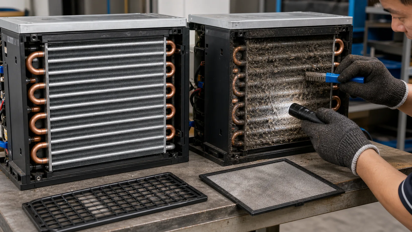
Tighter fin spacing increases surface area in a fixed face, but it also creates narrower air passages. In a clean mechanical room that trade may be acceptable. At floor level in a kitchen, dust, lint and grease can raise pressure drop quickly.
Specify the filter or screen, how it is removed and whether staff can reach it without moving the machine. Define the expected cleaning tool. Aggressive brushing can fold fins, while a fixed coil that cannot be rinsed safely may accumulate residue. The supporting condenser fin design guide explains how spacing, airflow and cleaning need to be reviewed together.
Tube, fin, casing and coating boundaries
Specify refrigerant, design pressure, tube material and wall requirement, fin material and thickness, casing material, joint method, connection geometry and corrosion exposure. Add coating only after confirming why it is needed and how it affects heat transfer, pressure drop, drainage, repair and inspection.
Do not claim that one material is universally best. Copper tube with aluminum fins, all-aluminum construction and other combinations each create different cost, mass, corrosion and manufacturing decisions. The suitable choice depends on refrigerant, pressure, environment and production process.
Keep food-zone and condenser-zone requirements separate
NSF/ANSI 12 covers sanitation and food-protection requirements for automatic ice making equipment and related components. The condenser may sit outside the food-contact zone, but its placement must not make the appliance difficult to clean or drive dirty air through a protected area.
Ask the complete-machine compliance team to define material and cleanability requirements for each zone. A coil supplier can return component data. It cannot certify the complete appliance from a coil drawing alone.
Coordinate refrigerant, pressure, circuiting, fan and controls
The condenser is part of a refrigerant circuit and control loop. Changing one interface can move operating pressure, charge, compressor load or harvest behavior.
Refrigerant and pressure data
Provide the approved refrigerant and any applicable lubricant constraints. State design and test pressures, allowable pressure drop, mass flow or compressor data, inlet state, target outlet condition, connection sizes and orientation. If a lower-GWP or flammable refrigerant is under review, keep charge, ignition-source, ventilation and safety evaluation with the responsible appliance team.
Do not substitute refrigerants from a property table and leave the coil unchanged. Saturation pressure, density, pressure drop, heat-transfer coefficient, circuit volume and safety controls may all change.
Fan operating point and head-pressure strategy
For an air-cooled coil, request the fan curve, motor data, control range and intended operating point through the installed resistance. Confirm whether the fan runs continuously with the compressor, cycles, varies speed or follows another control. Review minimum ambient and low-load behavior so the system can maintain the pressure needed for stable expansion and harvest control.
For a water-cooled condenser, return the water-control method and expected pressure range. For a remote condenser, lock the approved head-pressure control and fan interface rather than treating the remote coil as a passive part.
Sound, vibration and condensate exposure
State the sound measurement boundary and operating state. Moving a condenser outdoors can reduce indoor fan noise but introduce roof or structural vibration. A deeper self-contained coil may allow a lower fan speed, but only if the cabinet and grille preserve the required airflow.
Show mounting points, isolators, fan balance requirements, cable routing and exposure to condensate or cleaning water. Validate sound with the complete cabinet fitted, not with a bare fan on a bench.
Lock the cabinet, remote frame and service envelope
Thermal selection is not drawing release. The supplier needs a controlled dimensional package:
- maximum face width, height, depth and mass;
- tube and connection locations in three axes;
- mounting holes, brackets, casing flanges and tolerances;
- fan, shroud, grille and filter interfaces;
- compressor, receiver, valve, drain and wiring clearances;
- coil removal direction and minimum service travel;
- shipping protection and handling points;
- remote frame, electrical and weather interfaces where applicable.
Use a sample or scan when replacing an existing condenser, but do not let a sample become the only specification. Record damaged fins, bent casing and field-modified connections so they are not copied into production drawings.
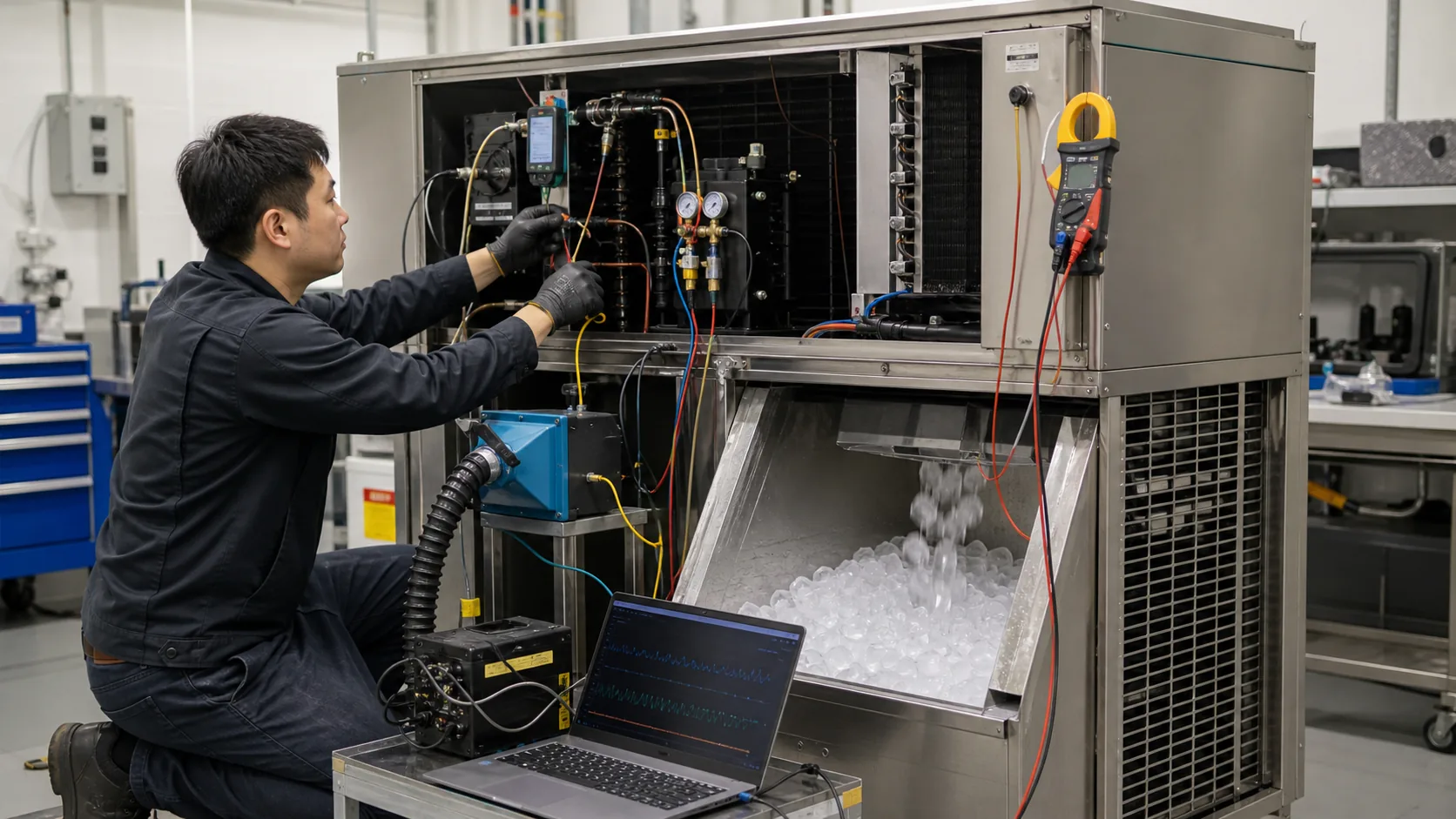
Validate the prototype through complete ice-making cycles
Component tests and machine tests answer different questions. A pressure test can verify containment. A performance test at stated conditions can verify a coil duty. Neither proves that the ice machine will produce the intended ice across its operating envelope.
Create a matrix that includes stable freeze operation, harvest, warm start, high condenser entering condition, minimum intended ambient, clean airflow, defined restricted airflow, water-loop extremes where applicable, remote-line extremes, bin-full restart and any sanitation or cleaning recovery state that affects the refrigeration system.
Record ice production and cycle times together with condenser entering and leaving conditions, refrigerant pressures and temperatures, compressor and fan or pump power, airflow or water flow, control outputs, sound and vibration. Choose calibrated sensors, then record their accuracy, sampling interval and test duration.
Separate component evidence from machine evidence
The supplier should identify what its data proves. A coil rating may cover heat rejection and pressure drop at stated conditions. A pressure or leak test covers containment. Material certificates cover supplied material when contractually required. Complete ice production, sanitation, energy, acoustic and safety results belong to the assembled machine test unless the contract states otherwise.
Test beyond the nominal pass point
A single nominal pass hides margin. Increase entering-air or water temperature in controlled steps, reduce airflow or water flow to a defined condition and observe where cycle time, condensing pressure or controls become unacceptable. This does not create a universal rating. It shows the project team how close the design sits to its intended boundary.
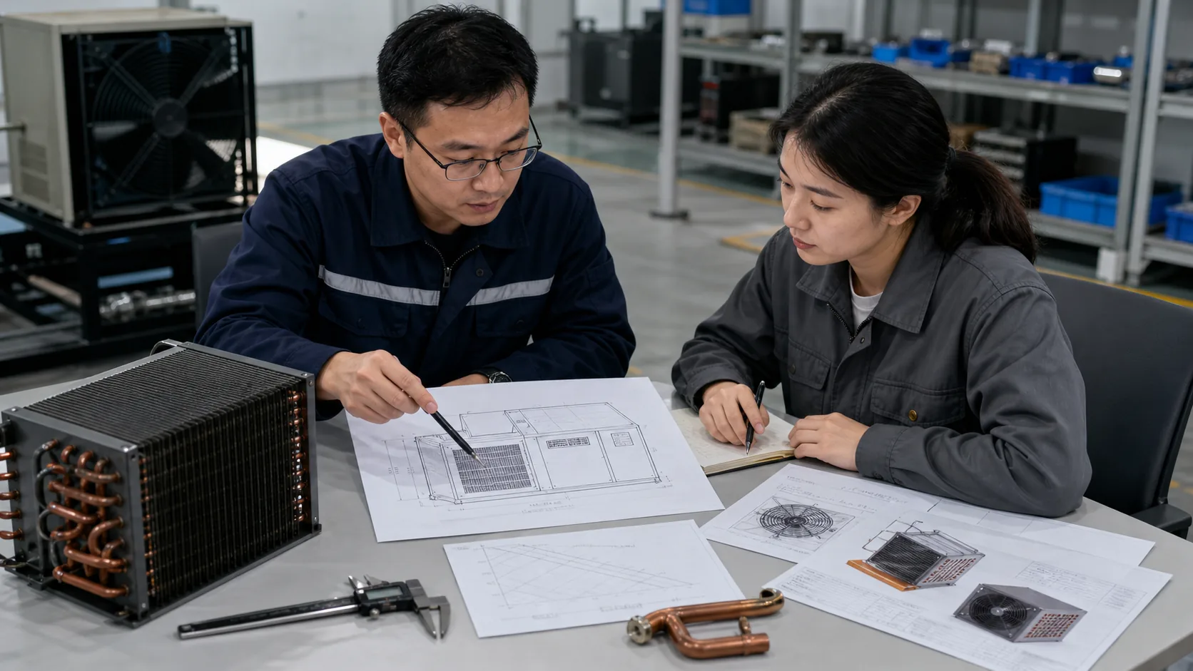
Normalize every supplier return before comparing price
Price comparison should begin after technical returns use the same basis. Require each supplier to state assumptions, exclusions and deviations.
| RFQ field | Supplier return | Why procurement needs it |
|---|---|---|
| Machine and cycle basis | Freeze, harvest and other duty states used | Confirms that capacity is not based on an unrelated steady load |
| Thermal rating | Heat rejection, entering condition, outlet condition and tolerances | Puts all proposals at the same rating point |
| Refrigerant side | Refrigerant, flow or compressor basis, pressure drop, circuiting and internal volume | Supports system and charge review |
| Air or water side | Airflow and pressure drop, or water flow and pressure drop | Connects the heat exchanger to fan, grille, pump or valve selection |
| Construction | Tube, fin or secondary surface, casing, joints, coating and connections | Reveals material and manufacturing differences |
| Controls and auxiliaries | Fan or valve data, control range and electrical interfaces | Prevents missing scope between component suppliers |
| Mechanical fit | Drawing, tolerances, mass, mounts and service-removal path | Protects cabinet and installation release |
| Validation | Proposed tests, conditions, reports and exclusions | Shows what evidence will be available before production |
| Commercial terms | Tooling, sample price, unit price, MOQ, lead time and validity | Keeps commercial inputs tied to the proposed technical scope |
Ice machine condenser coil RFQ checklist
Machine architecture and production objective
- Ice type and batch or continuous process
- Target production and rating basis
- Self-contained, water-cooled, remote condenser or remote condensing-unit architecture
- New design, replacement, cost-down or capacity-change objective
- Complete refrigeration schematic and control sequence
Duty and operating states
- Freeze, harvest, recovery and standby heat-rejection basis
- Compressor model or refrigerant state and mass-flow data
- Nominal and worst intended operating points
- Measured, calculated and assumed fields clearly marked
- Required performance tolerance and design margin policy
Air, water or remote heat sink
- Entering-air range, airflow path, fan curve, grille and filter loss
- Or entering-water range, flow, pressure, quality and control method
- Or remote ambient, matched equipment, route, line sizes, length, elevation and charge/control responsibility
- Fouling, corrosion, grease, salt or weather exposure
- Cleaning method and service interval target
Refrigerant, pressure and controls
- Refrigerant and lubricant constraints
- Design and test pressures
- Allowable refrigerant pressure drop and internal volume target
- Connection sizes, location and orientation
- Fan, pump or water-valve electrical and control data
- Head-pressure strategy across the operating range
Mechanical, service and validation requirements
- Controlled cabinet or frame drawing and 3D envelope
- Mounting, tolerance, mass and handling limits
- Coil, fan, filter and line service-removal paths
- Prototype quantity and drawing-approval process
- Pressure, leak, dimensional and performance tests
- Complete-machine test conditions and required supplier report format
You can also adapt the broader custom refrigerator coil RFQ checklist when the project needs common drawing, packaging and supplier-return fields.
Frequently asked questions
Does compressor horsepower provide enough data to select the condenser?
No. A horsepower value omits refrigerant, compressor efficiency, operating condition, evaporator load, harvest sequence and condenser entering condition. Use compressor performance or measured system data to establish heat rejection at the required states.
Is the highest condenser load always during the freeze cycle?
Not necessarily. The answer depends on the machine architecture, compressor operation, harvest method, controls and recovery conditions. Build a state matrix and verify the actual peak and sustained limits instead of assuming one cycle label owns the design point.
When should an ice machine use a remote condenser?
Consider a remote condenser when indoor heat or fan noise is unacceptable and the project can support the manufacturer’s approved line route, ambient range, charge, controls, weather exposure and service access. It is a system decision, not a coil-only substitution.
Is a water-cooled condenser better in a hot kitchen?
It can reduce dependence on kitchen air, but it needs a suitable water source or loop, acceptable water use, water-quality control, pressure and flow, a legal discharge arrangement and a maintenance plan. Compare the complete installed cost and utility boundary.
How should condenser fouling be included in selection?
Define the contaminant, filter or screen, cleaning method and acceptable service interval. Ask for clean pressure drop and a documented restricted-airflow test point. Do not apply an undocumented capacity multiplier and call it a fouling allowance.
What should I send for an ice machine condenser quote?
Send the machine architecture, cycle heat-rejection states, refrigerant and compressor data, air or water conditions, remote piping where applicable, fan or control data, dimensional drawings, materials, service access, validation requirements, quantity and project schedule.
Send the complete machine boundary, not a single capacity number
An effective ice machine condenser RFQ lets the supplier see where heat comes from, where it must go and which interfaces are already locked. That reduces the chance of comparing coils selected at different conditions or discovering the installation limits after a prototype is built.
Domi can review a cabinet drawing, refrigeration schematic, cycle data, airflow or water conditions and existing condenser sample for a custom commercial refrigeration coil discussion. Send the known data first and mark open items clearly. Request a drawing and duty review before releasing the condenser package for tooling or production.