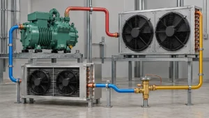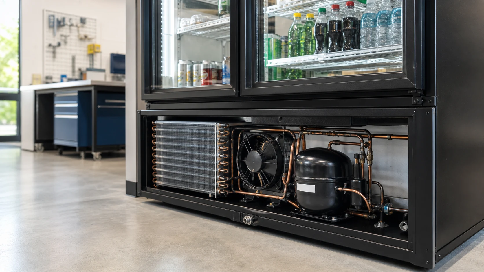
Beverage cooler condenser coil selection should start with the complete cabinet’s heat-rejection duty at the actual condenser entering-air condition. The coil, fan, shroud, grille, refrigerant circuit, machine compartment, fouling allowance, noise target and service clearances must be reviewed as one installed package. Compressor horsepower or outside coil dimensions alone do not define a valid selection.
A beverage cooler may look like a simple refrigerated cabinet, but its condenser works inside a tight and changing environment. The front door opens. Warm products are loaded. Lights, fans and anti-sweat devices add heat. The compressor rejects its own input power through the condenser. Dust collects at the intake. Warm exhaust air can return to the coil if the machine compartment has no controlled air path.
These effects explain why a condenser that performs well on an open test bench can run at a higher condensing condition after installation. Lack of coil surface is only one possible cause. A restricted grille, an unmatched fan, leakage around the shroud, a blocked service panel or poor separation between intake and exhaust can produce the same symptom.
This guide is for OEM engineers, cabinet developers and sourcing teams selecting a new or replacement condenser for a beverage cooler. It covers the data needed to compare proposals and release a prototype for testing. It does not replace the complete refrigeration-system design, appliance safety review, certification process or final supplier rating.
Define the beverage cooler duty before selecting the condenser
The first question is what the cooler must do. A cabinet that only holds pre-cooled cans at a stable setpoint has a different operating profile from a display cooler that receives warm product several times per day. A back-bar cooler with frequent door openings has a different infiltration pattern from a wine cooler that is opened occasionally.
Write the operating states before asking for a condenser:
- normal holding with the expected product load;
- door-opening and customer-use periods;
- restocking with the product entering at a defined temperature;
- pull-down after startup or scheduled shutdown;
- high-ambient operation around the cabinet;
- part-load and low-ambient operation, if relevant;
- recovery after cleaning, service or an abnormal door-open event.
The complete equipment category also matters. The current ENERGY STAR commercial refrigerator and freezer criteria include product types such as back-bar coolers and bottle coolers within defined whole-appliance classes. Their energy performance is evaluated at equipment level. A low-power condenser fan does not prove that the cabinet meets an energy target if the compressor runs longer, the coil receives recirculated air or the door system has a high load.
Do not turn an equipment classification into a coil rating. Use it to clarify the cabinet configuration, temperature class, door type and test route, then give the condenser supplier the thermal and mechanical data needed for the component.
Separate holding duty from recovery duty
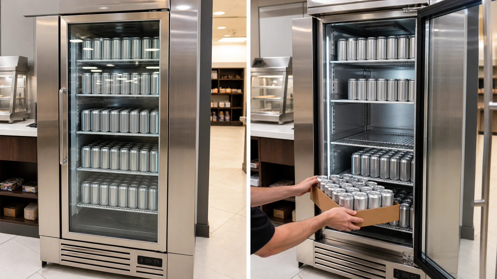
Holding duty is the heat that must be removed after the cabinet and product have stabilized. It can include heat leakage through the enclosure, door infiltration, internal fans, lights and other controlled loads. Recovery duty adds a time requirement. The system must remove the heat introduced by door use, warm product or a startup condition and return the cabinet to its target range.
A supplier cannot infer this profile from cabinet volume. Provide product mass, product entering temperature, loading pattern, door type, opening frequency, ambient condition and the recovery target used by the equipment designer. When a value is still being developed, label it as preliminary and ask the supplier to identify the assumption used in the proposal.
Calculate the condenser requirement from heat rejection, not cabinet capacity alone
The condenser rejects more heat than the evaporator absorbs. At a steady operating point, the condenser heat-rejection duty is approximately the evaporator load plus the compressor input that becomes heat. Auxiliary heat that enters the refrigerant or condenser air path may also need to be included according to the system boundary.
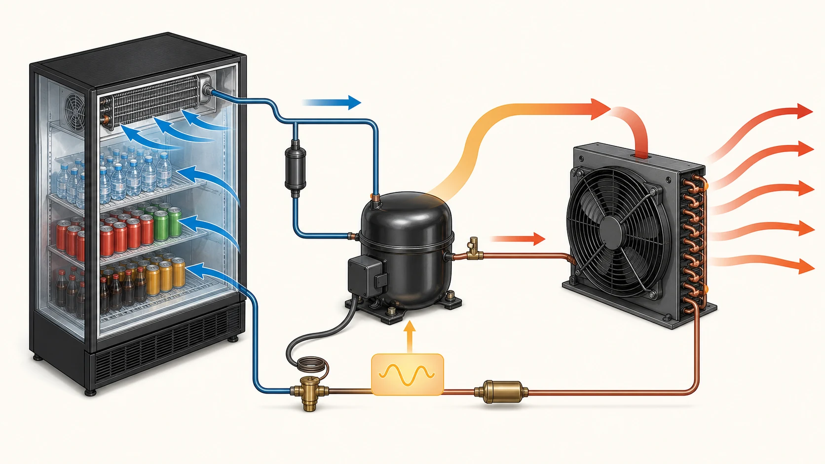
This relationship is simple, but it prevents a common RFQ error. A buyer may request a condenser for a cabinet described as having a certain cooling capacity and send no compressor performance data. Two compressor selections can deliver a similar evaporator capacity while producing different discharge conditions and input power. The condenser requirement therefore changes.
Use compressor or system performance data at the stated refrigerant, evaporating condition, condensing condition, superheat, subcooling and ambient. Do not add a universal percentage to cabinet capacity and treat the result as a released design. A planning margin may be useful, but it must be identified, justified and checked against the compressor operating envelope and the complete equipment test.
For broader load and face-velocity inputs, the commercial refrigeration coil sizing guide explains why capacity must stay tied to rating conditions. The beverage-cooler condenser RFQ should carry that same discipline into the heat-rejection side.
State the boundary behind every duty value
A useful duty statement answers four questions:
- Is the value evaporator capacity, compressor heat rejection, or a complete condensing-unit rating?
- At which refrigerant and operating conditions was it calculated?
- Does it represent holding, pull-down, recovery or a high-ambient state?
- Which fan power, lighting, controls and auxiliary loads are inside the boundary?
If the supplier returns only a nominal watt or BTU/h value, ask for the rating point and assumptions. A number without its boundary cannot be compared with another proposal.
Set the rating points and operating envelope
One nominal point is rarely enough for beverage cooler condenser coil selection. The design point may control the coil size, but other states control compressor reliability, energy use, noise and cabinet recovery.
At minimum, define:
- refrigerant and compressor model or approved operating envelope;
- evaporating and condensing conditions used for selection;
- expected subcooling and refrigerant-side pressure-drop limit;
- cabinet ambient range and installation environment;
- condenser entering-air temperature inside the machine compartment;
- airflow or fan curve and available static pressure;
- electrical supply, fan control and compressor control method;
- maximum envelope, connection positions and service clearances.
The air entering the condenser can be warmer than the room. The compressor, discharge line, fan motor and restricted machine compartment all add heat. Exhaust air may also recirculate. Measure or estimate the entering-air condition at the coil location, not in an open part of the room that the condenser never sees.
Copeland’s commercial refrigeration condensing-unit guidance also treats application requirements, ambient conditions, ventilation and heat rejection as core selection inputs. Use such guidance to define the equipment boundary. Use project-specific coil and compressor data for the final selection.
Add off-design checks
Review at least one high-ambient or restricted-airflow condition and one part-load or low-ambient condition when the application can encounter them. At high ambient, the condenser has less temperature difference available to reject heat. At low load, an aggressive fan or control strategy may drive the condensing condition below the range intended by the rest of the system.
The equipment designer should decide how fan cycling, variable speed, head-pressure control and compressor control work together. The coil supplier should state the proposed performance basis and what must still be confirmed in the complete cabinet.
Recover the real condenser airflow path
The fan moves air through the complete compartment, rather than only through the coil. The path can include an intake grille, dust screen or filter, the condenser face, a shroud or fan panel, a guard, internal obstructions and an exhaust opening. Each item adds resistance. Gaps around the coil or shroud create bypass.
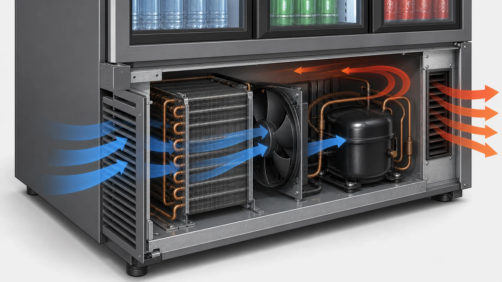
Draw the airflow path in plan and section views. Show the finished cabinet panels along with the refrigeration deck. Mark:
- fresh-air intake area and ground clearance;
- coil face and airflow direction;
- fan diameter, rotation, position and shroud;
- compressor and piping obstructions;
- exhaust opening and discharge direction;
- seals that prevent bypass;
- barriers that separate warm exhaust from intake air;
- removable panels and cleaning access.
Warm-air short-circuiting can make a large coil behave like a small one. If exhaust turns around a cabinet corner and immediately re-enters the intake, the condenser sees warmer air. Increasing fan speed may make the loop stronger. Better separation or grille placement can be more effective than adding fan power.
Compare fans at the installed operating point
Free-air volume is not the airflow through a finished condenser compartment. Ask for the fan curve, the proposed operating point and the system boundary used to estimate resistance. Include the coil in its clean state and the intended grille, guard and filter condition.
If the cabinet uses speed control, specify the minimum and maximum commands, feedback signal, fault response and operating sequence. The adjacent cold room evaporator fan selection guide explains the same duty-point principle on the evaporator side. For a beverage cooler condenser, the physical arrangement is smaller, but the fan and resistance curves still meet at an installed operating point.
Protect the intake during installation
A laboratory cabinet may receive clear air while the production unit sits against a wall, under a counter or beside another heat-producing appliance. State the minimum installation clearances and check the most likely real placement. If a front-breathing design is required, confirm that both intake and exhaust paths remain functional after the decorative grille and kick plate are installed.
Compare condenser construction options against the cabinet
The useful construction depends on duty, envelope, airflow, refrigerant, production method, cleaning route and cost. A supplier may propose a finned-tube coil, wire-on-tube condenser, tube-on-plate arrangement, microchannel core or another design. The names do not make the options interchangeable.
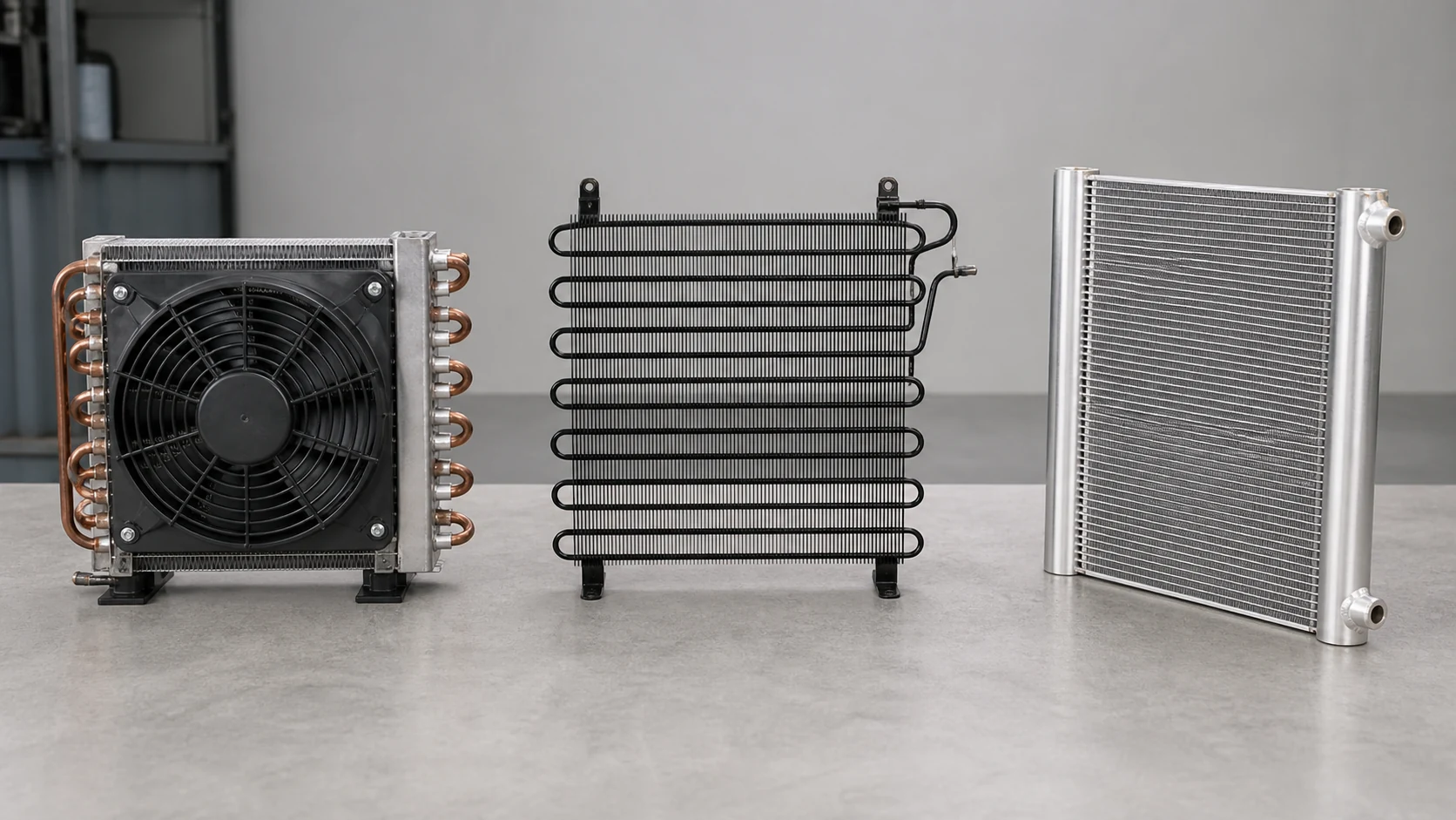
Finned-tube condenser
A finned-tube condenser provides high external surface area in a compact package and is common where a fan moves air through a defined machine compartment. Tube diameter, fin pitch, row count, circuiting, face area and fan match all affect performance.
Its compact fin pack can collect dust. A tight pitch that performs well when clean may need more frequent cleaning or a larger pressure allowance in a dirty retail environment. The design should provide access that does not require damaging the fins.
Wire-on-tube or tube-on-plate arrangement
Wire-on-tube and tube-on-plate condensers can suit appliance layouts where natural or assisted convection, production method and cabinet surface arrangement support them. They use a different surface and airflow concept from a compact fin pack. The available mounting area, orientation, proximity to the cabinet wall and heat path therefore matter.
Do not replace one construction with another solely because the outside dimensions fit. Confirm heat rejection, refrigerant volume, pressure drop, mounting stiffness, noise, finish and production interfaces.
Microchannel condenser
Microchannel construction can provide a compact refrigerant-to-air core, but it changes circuiting, joining, charge distribution, coating, repair and manufacturing questions. The equipment designer and supplier must confirm that the proposed core, headers and connections suit the refrigerant, pressure boundary, production process and service plan.
There is no universal winner. Ask each supplier why its proposed construction fits the cabinet and what trade-off comes with it. The refrigeration condenser coil guide provides the broader construction context; the final decision still belongs to the beverage cooler project.
Coordinate refrigerant, circuiting and appliance safety
The refrigerant changes compressor data, saturation conditions, mass flow, pressure levels, connection details and the complete appliance safety route. State the exact refrigerant or approved alternatives. Do not use a family label such as low-GWP refrigerant as a substitute for a named design basis.
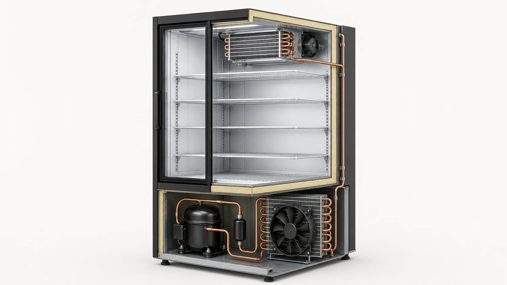
Circuiting must keep refrigerant pressure drop, distribution, oil management and subcooling within the system designer’s targets. Define inlet and outlet location, tube and connection sizes, orientation, joint method, allowable internal volume if controlled, and whether the condenser includes a receiver section, subcooling section or other project-specific feature.
For flammable refrigerants, the coil is one part of a complete safety design. UL’s mechanical refrigeration code overview identifies UL/CSA 60335-2-89 as an applicable route for commercial refrigerating appliances including beverage coolers. The appliance manufacturer must coordinate charge, leakage paths, ignition-source control, components, enclosure and applicable listing or certification requirements. A condenser supplier should provide accurate component data but should not declare the complete appliance compliant.
Keep thermal changes connected to safety review
A change intended to reduce condensing temperature may alter coil volume, joint count, fan wiring, airflow around electrical components or the physical location of refrigerant-containing parts. Route those changes through the appliance’s engineering and safety review. Record which values were calculated, measured, supplier-rated or confirmed through certification work.
Balance capacity, energy, sound and control
A larger condenser can reduce the temperature difference needed for heat rejection at a given condition, but it can also change refrigerant volume, airflow resistance, material cost, cabinet space and fan selection. More surface is not automatically the lowest-energy system.
Compare proposals at the same heat-rejection duty, entering-air temperature, refrigerant condition and airflow boundary. Ask for fan input, compressor effect, pressure drop and control assumptions. A proposal with a low fan wattage may force a higher condensing condition. A high-airflow proposal may lower condensing temperature but create unacceptable noise or discharge velocity.
Whole-cabinet performance matters. AHRI’s commercial refrigerated display merchandiser and storage cabinet rating scope is a reminder that the equipment is rated as an operating system. A component supplier’s coil result should feed the cabinet validation; it does not replace it.
Define the sound boundary
State where sound matters and how it will be evaluated. A beverage cooler placed in a quiet tasting room has a different acoustic requirement from a noisy kitchen. Record fan speed, compressor state, cabinet panels, grille, floor contact and measurement position with the result.
Noise can come from blade passage, turbulent grille flow, coil whistle, motor tones, compressor vibration, loose panels or piping contact. Do not ask the condenser supplier for one sound number without identifying which sources and installation state are included.
Design for dust, grease, cleaning and corrosion
The condenser sees room air, not ideal laboratory air. Retail dust, cardboard fibers, pet hair, kitchen grease and cleaning chemicals can reduce airflow or attack surfaces. State the installation environment and the approved maintenance method.
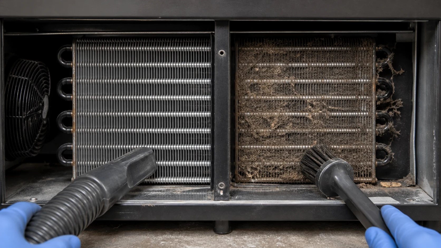
Fin spacing is one part of the response. Wider spacing can improve tolerance to contamination but changes surface area and envelope. A filter or screen can protect the coil but adds resistance and creates a maintenance task. A coating may help in a confirmed exposure but can change heat transfer, pressure drop, drainage, manufacturing and repair.
The commercial condenser fin design guide and commercial refrigeration coil coating guide cover those subjects in more depth. For the beverage cooler, keep the decision tied to the intake location, cleaning access, service interval and chemicals that the operator will actually use.
Provide a straight cleaning path. If the only way to reach the condenser is to remove refrigerant piping or bend a fan bracket, routine maintenance will be delayed or performed poorly. Protect the fins from the brush, vacuum nozzle and panel edge used during service.
Lock the cabinet fit, production interfaces and service envelope
A thermally correct selection can still fail in production when the drawing omits mounting, connection or service details. Send the complete machine-compartment envelope and identify which dimensions are fixed and which can change.
Control these interfaces:
- coil face, depth and orientation;
- bracket, hole, datum and tolerance scheme;
- tube and header keep-out zones;
- inlet, outlet and service-port positions;
- compressor, fan, shroud and grille relationship;
- electrical harness and sensor clearance;
- drain or condensate route if present nearby;
- panel removal and tool access;
- packaging supports and handling points.
Use one approved drawing revision for quotation, prototype inspection and production release. If a cabinet panel, fan, compressor or refrigerant changes, record whether the condenser rating and fit remain valid. A sample is useful for fit-up, but it does not carry the operating conditions or acceptance criteria on its own.
Validate the prototype across real operating states
Prototype validation should answer the decisions made during selection. It should not be a single photograph of a running cabinet or one air temperature measured without context.
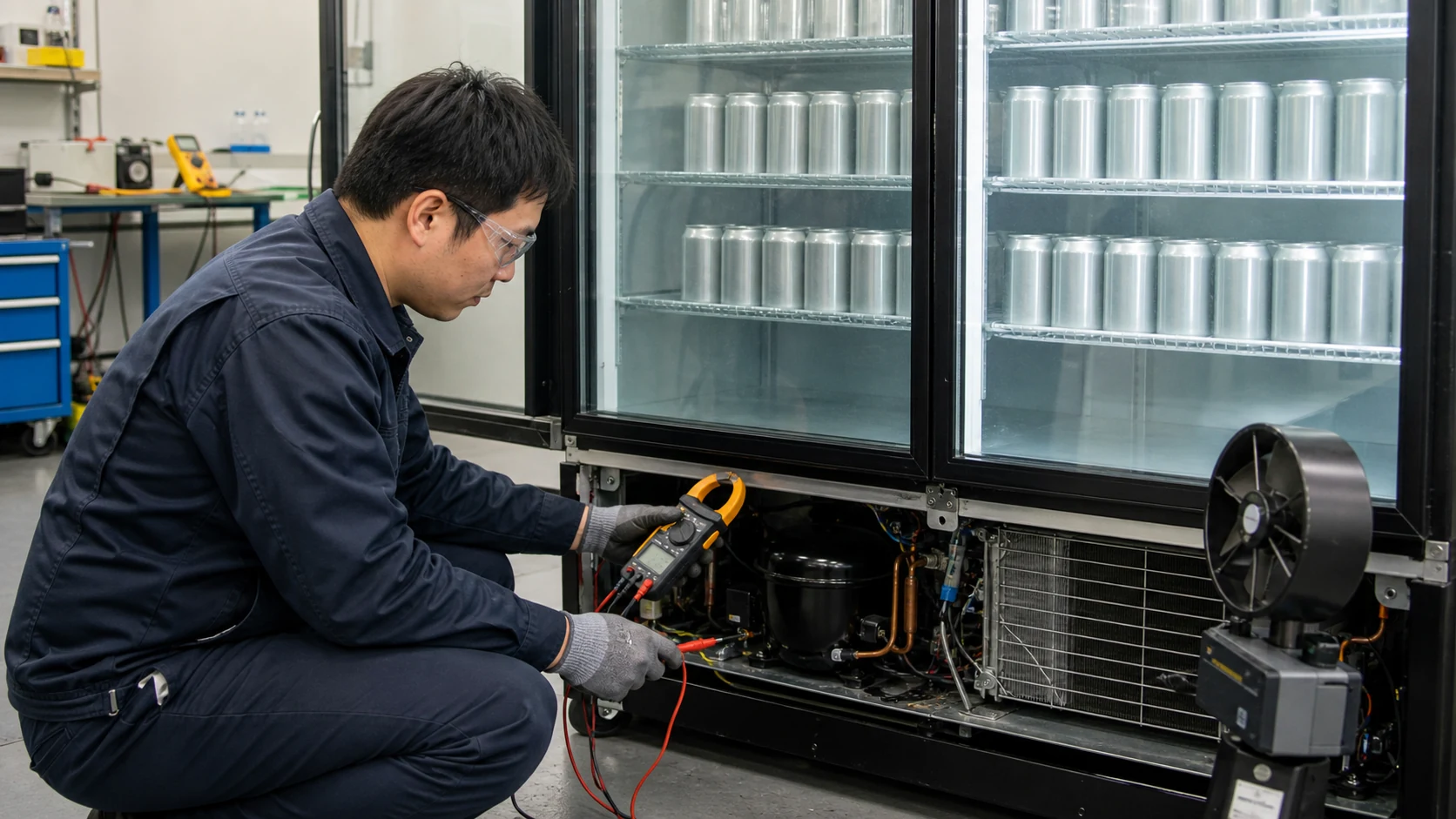
Create a test matrix that covers the approved states. Depending on the project, this may include:
- stabilized holding at the declared ambient;
- door-opening or customer-use sequence;
- warm-product loading and recovery;
- startup or pull-down;
- high ambient around the installed cabinet;
- clean and defined restricted-airflow conditions;
- minimum and maximum fan command;
- intended installation clearance;
- sound and vibration with all cabinet panels fitted;
- restart after a power interruption or control event.
Record cabinet air and product temperatures, condenser entering and leaving air, refrigerant conditions at useful points, compressor and fan power, airflow evidence, operating times, control states and abnormalities. Use calibrated instruments and a documented method appropriate to the decision.
Separate coil evidence from cabinet evidence
A coil test can confirm dimensions, pressure integrity and performance under its stated setup. A cabinet test can reveal recirculation, panel leakage, door load, control interaction and installation effects. Keep both records and do not use one as a substitute for the other.
The supplier should identify which result is calculated, which is measured on a component rig and which requires the buyer’s complete prototype. If a value falls outside the agreed range, record the deviation and the drawing or control change that follows.
Compare supplier proposals on one returned-data sheet
Require every supplier to return the same fields. Leave space for deviations and missing data instead of forcing a simple compliant box.
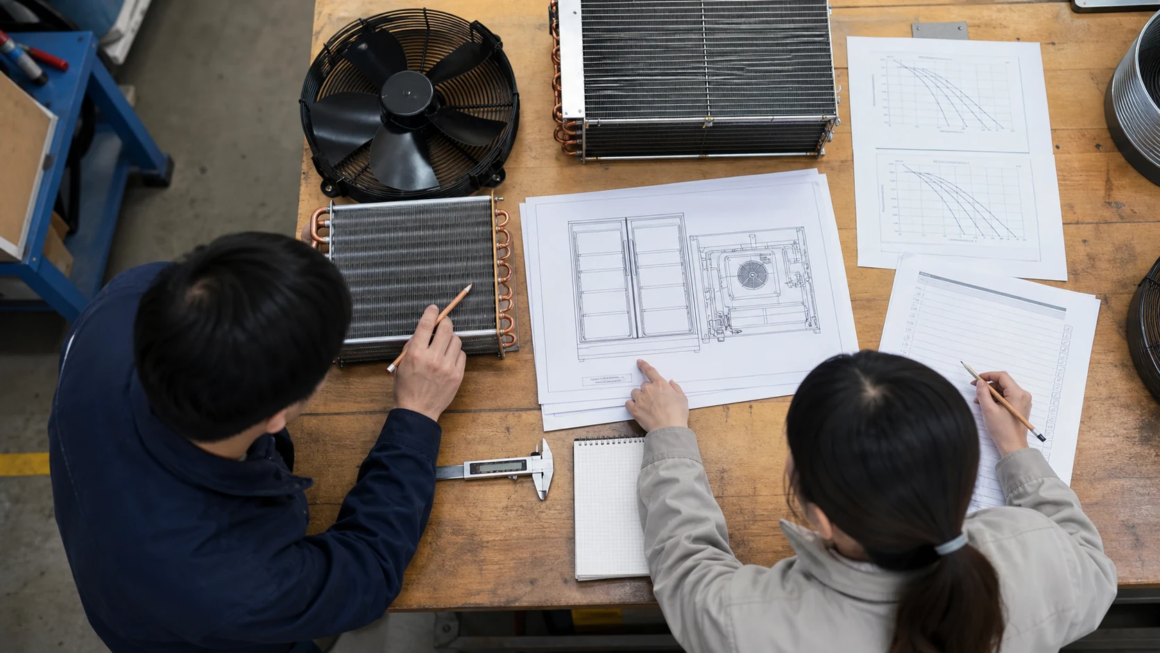
| Comparison field | Buyer-supplied basis | Supplier return |
|---|---|---|
| Heat rejection | Duty and each rating state | Capacity, assumptions and margin |
| Air side | Entering-air condition, fan data, grille and envelope | Airflow, pressure drop and operating point |
| Refrigerant side | Refrigerant, conditions, flow basis and limits | Circuiting, pressure drop, internal volume and connections |
| Construction | Cabinet constraints and exposure | Tube, fin, header, coating, joints and mounting |
| Controls | Fan supply, command and cabinet sequence | Motor data, control range, feedback and fault behavior |
| Mechanical fit | Drawing, datums, keep-outs and service access | Dimensions, tolerances, mass and interface deviations |
| Validation | Required component and cabinet evidence | Proposed tests, setup, reports and exclusions |
| Commercial | Prototype quantity, production forecast and destination | Tooling, sample, unit price, MOQ, lead time and validity |
Do not compare unit prices until the technical basis matches. One supplier may include the fan, shroud and test report while another quotes a bare coil. One may rate a clean, open-air setup while another includes the production grille. The returned sheet exposes those differences before purchasing treats the quotes as equivalent.
Beverage cooler condenser coil RFQ checklist
Send the condenser request as one controlled package.
Application and duty
- cabinet type, door type, internal volume and product use;
- holding, loading, pull-down and recovery requirements;
- ambient range and installation location;
- heat-rejection duty at each required rating point;
- target operating range and acceptance criteria.
Refrigeration and air side
- refrigerant, compressor data and operating conditions;
- condensing target, subcooling and pressure-drop limit;
- fan model or curve, voltage, frequency and controls;
- intake, grille, filter, shroud and exhaust details;
- machine-compartment entering-air condition and clearance.
Mechanical and production
- 2D drawing and 3D model when available;
- coil envelope, datums, tolerances and mounting;
- connection sizes, positions, orientation and joint method;
- material, finish, corrosion and cleaning requirements;
- prototype quantity, annual volume, SKU family and packaging.
Validation and documentation
- pressure or leak-test basis defined by the project;
- dimensional inspection and critical characteristics;
- thermal, airflow, power, sound and vibration evidence required;
- sample approval route and drawing revision;
- applicable appliance standards, market and certification responsibilities;
- deviations, exclusions and open assumptions to be returned with the quote.
If a field is unknown, mark it open. An explicit unknown gives the supplier a chance to ask the right question. An invented value can send the entire design in the wrong direction.
Frequently asked questions
Can I select a beverage cooler condenser coil by compressor horsepower?
No. Horsepower does not define the required condenser heat rejection, refrigerant condition, cabinet ambient, fan operating point or machine-compartment airflow. Use compressor or system performance data at the actual rating states, then match the condenser and fan package to that duty.
Why is condenser heat rejection higher than beverage cooler capacity?
The condenser rejects the heat absorbed at the evaporator plus the compressor input that becomes heat, within the defined system boundary. That is why an evaporator capacity value cannot be copied directly into a condenser RFQ.
Does a larger condenser always reduce energy use?
Not always. More surface can reduce the required temperature difference at a matched duty, but the larger coil may change pressure drop, fan selection, refrigerant volume, cabinet fit and control behavior. Compare complete-system power and performance at the same operating states.
Is a wire-on-tube condenser better than a finned-tube condenser?
Neither construction is universally better. Wire-on-tube can suit certain appliance layouts and production methods. A finned-tube coil can provide compact forced-air heat rejection. The correct choice depends on duty, available area, airflow, refrigerant, cleaning, noise, mounting and production requirements.
Do door openings affect condenser selection?
Yes. Door openings and warm-product loading increase the evaporator load and compressor run time during recovery. The condenser must reject the resulting heat under the declared ambient and airflow conditions. The equipment designer should define the door-use and loading test rather than ask the coil supplier to guess.
What information should I send for a beverage cooler condenser quote?
Send the cabinet drawing, duty states, refrigerant and compressor data, ambient and machine-compartment temperatures, fan or airflow information, condenser envelope, connections, materials, cleaning environment, prototype plan, quantities and required evidence. Ask the supplier to return assumptions and deviations in writing.
Send the cabinet, condenser and airflow data together
The selection is ready for release only when the proposed coil can reject the required heat inside the real cabinet air path, across the required operating states, without exceeding the agreed limits for pressure, power, noise, fit and service access. Keep the cabinet drawing, fan data, compressor basis, refrigerant conditions and validation plan in one controlled package.
For a custom or replacement project, use Domi’s commercial refrigeration coil page to review the available application route, then send your beverage cooler drawing for review. Include the data you already have and identify open items instead of delaying the first technical discussion.