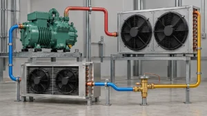
An OEM condenser coil specification should connect the system duty to a buildable coil drawing. State total heat rejection, refrigerant and design pressure, entering air condition, target subcooling, airflow, pressure drop, tube and fin materials, circuiting, connections, casing, corrosion exposure, inspection, and test evidence. A request that says only “condenser coil, copper tube and aluminum fin” leaves too many decisions open for a comparable quotation. This checklist gives equipment manufacturers and procurement teams the fields to define before requesting a custom condenser coil.
What the specification must accomplish
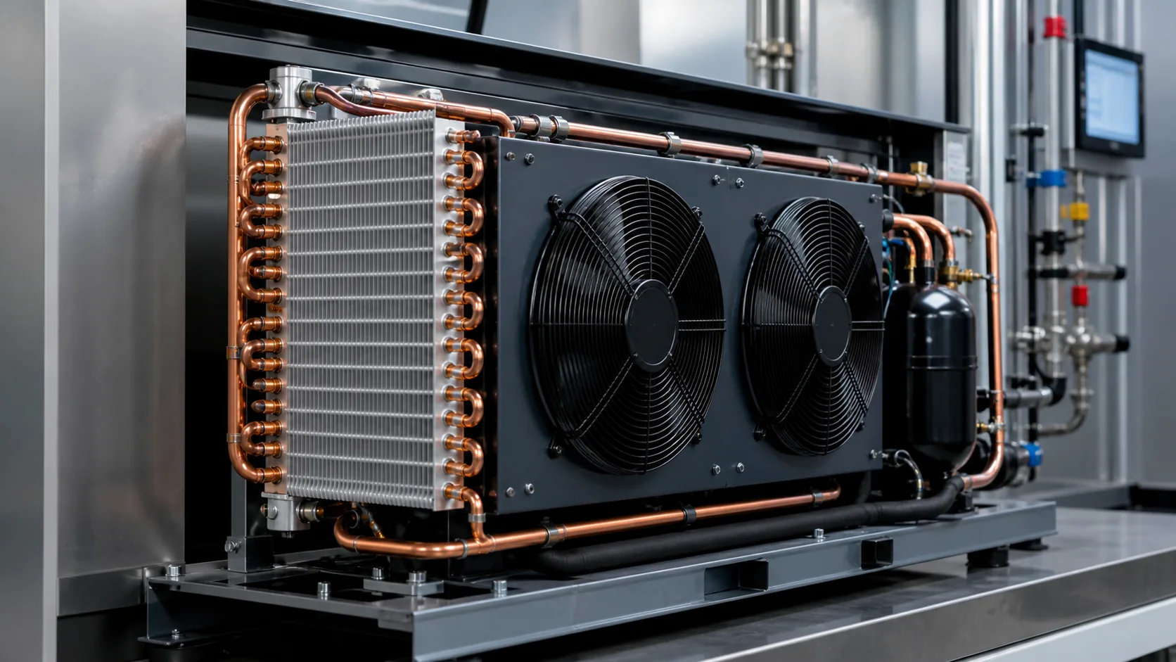
The specification has three jobs. It tells the engineer what performance the coil must deliver. It tells the manufacturer what geometry and materials to build. It gives quality and purchasing teams a way to compare offers without treating a lower price as an equivalent design.
The coil is also part of a larger high-side assembly. Compressor discharge piping, fan selection, receiver location, liquid-line routing, controls, ambient conditions, and service access can change the correct coil. The ASHRAE condenser chapter describes air-cooled condensers as heat exchangers that reject evaporator load plus compressor input. That is why an OEM specification should begin with system duty rather than a preferred tube diameter.
Define the application and equipment boundary
Identify the condenser type
Write whether the requirement is for an air-cooled, water-cooled, evaporative, remote, integrated, microchannel, plate-and-fin, or another construction. State whether Domi or the supplier is quoting the coil core only, a coil-and-frame assembly, a complete condenser, or a condensing unit with fans and controls.
The boundary changes the evidence required. A coil-only quote may need connection locations and pressure testing. A complete condenser quote also needs fan curves, motor data, guards, controls, sound, mounting, and wiring. Do not compare a coil-only price with a finished assembly price.
Identify the equipment and installation position
Record the equipment model family, indoor or outdoor location, service side, airflow orientation, footprint, maximum height, mounting points, and clearance restrictions. If the condenser is remote, state line length, elevation difference, receiver arrangement, and expected liquid-line pressure drop.
Heat rejection duty and rating conditions
Specify total heat rejection, not only refrigeration capacity
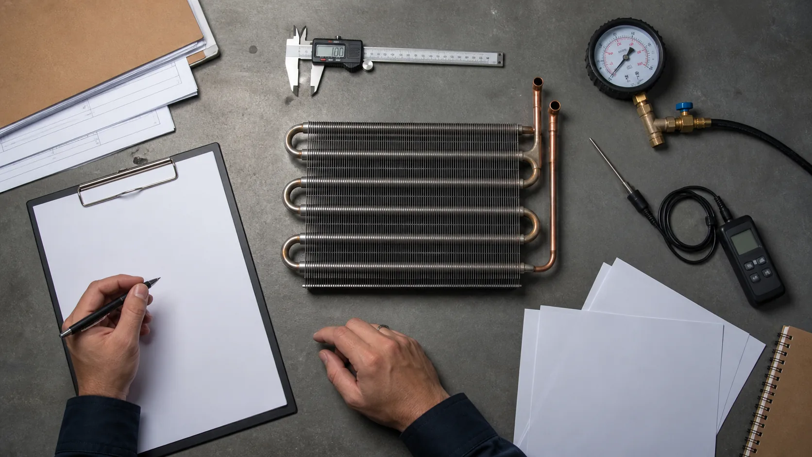
The condenser must reject the evaporator load plus compressor heat and other defined inputs. Use total heat rejection when comparing condenser ratings. If the equipment team starts with net refrigeration effect, record the compressor model, operating point, motor input assumption, and conversion method used to reach total heat rejection.
State the rating point and allowable envelope
Include refrigerant, evaporating condition, saturated condensing temperature or condensing pressure, entering air dry-bulb temperature, airflow, target liquid temperature, and any required subcooling. Include minimum and maximum operating points if the equipment will run across seasons or with capacity control.
| Rating field | What to state | Why it affects the quote |
|---|---|---|
| Heat rejection | Total condenser duty at the named operating point | Prevents a refrigeration-capacity figure from being mistaken for condenser duty |
| Air condition | Entering dry-bulb, humidity when relevant, and ambient range | Changes the air-to-refrigerant temperature difference and condensation behavior |
| Refrigerant condition | Refrigerant, saturated condensing condition, inlet superheat, and liquid outlet target | Defines the refrigerant-side load and any desuperheating or subcooling zones |
| Airflow | Volume flow, fan speed or fan curve, and allowable air-side pressure drop | Connects coil performance to the actual fan and cabinet |
Use units, tolerances, and measurement locations in the rating schedule. A supplier should identify every assumption that is not supplied by the OEM.
ASHRAE guidance explains that air-cooled condenser selection is commonly based on the temperature difference between entering cooling medium and saturated condensing temperature. The same coil can show very different capacity, pressure drop, and fan power at different TD values. A quotation without a rating condition is not comparable.
Separate the design point from the control limit
The design point is used to size the coil. The control limit is the condition at which the system must still protect the compressor, maintain liquid feed, or manage low ambient. Put both in the specification. For example, a summer design point may define heat rejection while a winter condition defines fan cycling, head-pressure control, or minimum condensing pressure.
Refrigerant, pressure and subcooling fields
Refrigerant and oil compatibility
State the refrigerant designation, blend glide if relevant, oil family, and any restrictions on internal cleanliness. If the system may change refrigerant, treat that as a design review. A new refrigerant can change mass flow, pressure, discharge temperature, circuiting, and material requirements.
Design pressure and test pressure
Specify design pressure for the high side, allowable working pressure, test pressure, test medium, hold time, and acceptance criteria. Distinguish a factory strength or leak test from a field pressure test. The supplier should identify whether the test covers the entire circuit, each circuit separately, headers, brazed joints, and any factory-installed valves.
ASHRAE’s halocarbon system guidance notes that condenser refrigerant pressure drop must be obtained from the supplier for the particular unit and specified load. Put that result into the required submittal instead of accepting a generic pressure-drop statement.
Subcooling requirement
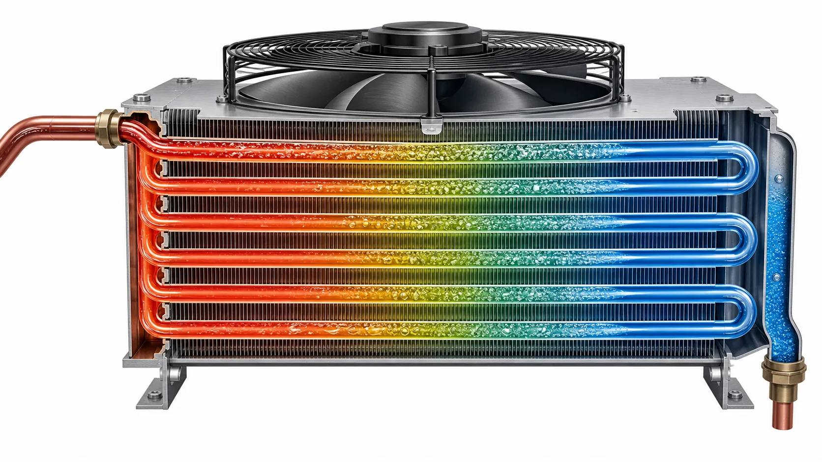
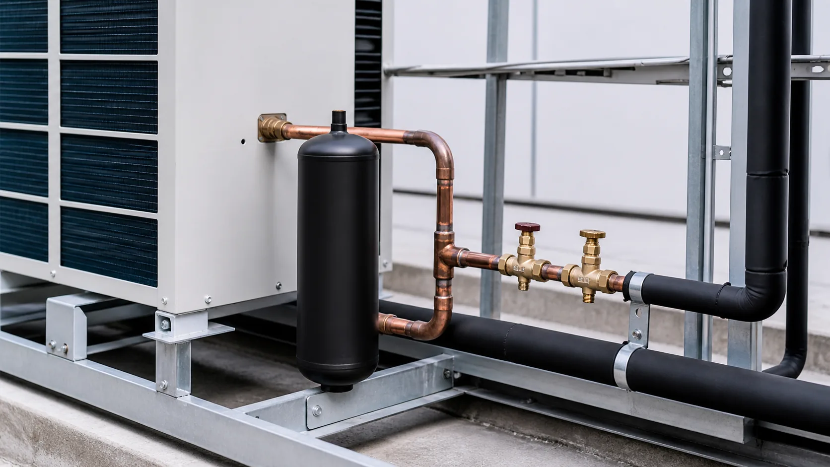
State required liquid temperature or subcooling at the condenser outlet, where it is measured, and whether the receiver is included. A circuit that provides extra subcooling can change refrigerant charge and liquid-line behavior. Make sure the rating sheet identifies the outlet condition and the measurement location.
Air-side duty, fans and clearances
Airflow and face velocity
Record design airflow, allowable air-side pressure drop, fan operating range, air inlet temperature, altitude, and whether air recirculation is expected. For an outdoor condenser, include solar load, prevailing wind, nearby walls, screens, and seasonal ambient. For an indoor unit, specify duct resistance and discharge path.
Fan arrangement
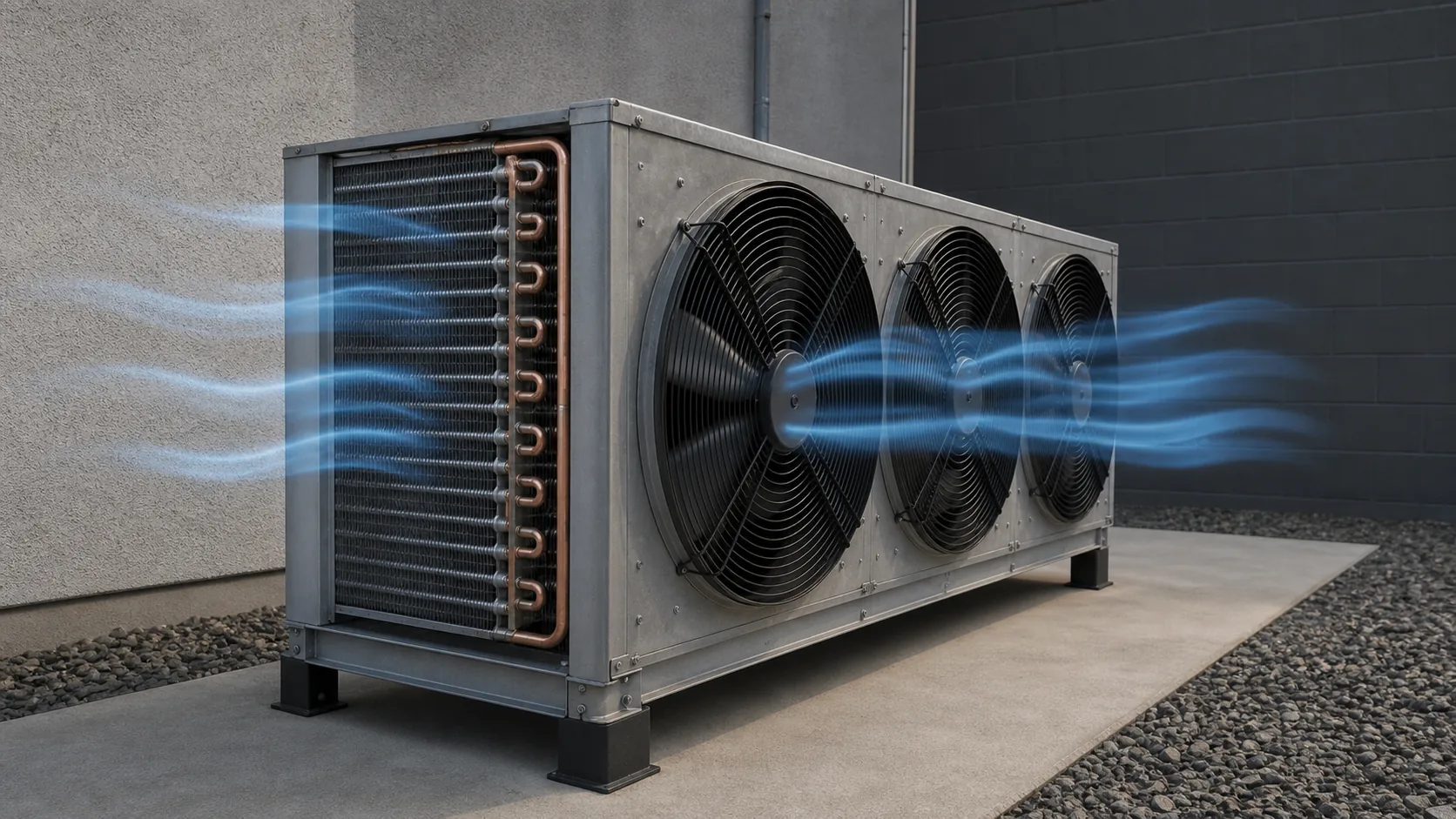
State draw-through or blow-through, fan diameter, number of fans, speed control, motor voltage, frequency, direction, guard, and service access. Ask for the fan curve at the coil pressure drop. A fan that delivers the required volume in free air may not do so through a dirty coil, guard, grille, or discharge duct.
Clearance and recirculation
Provide the minimum free area around the coil and fan. Recirculated hot air can raise entering air temperature and discharge pressure even when the nominal outdoor temperature looks acceptable. Ask the supplier to identify the assumed inlet and outlet clearances on the layout drawing.
Tube, fin, header and casing materials
Tube and fin construction
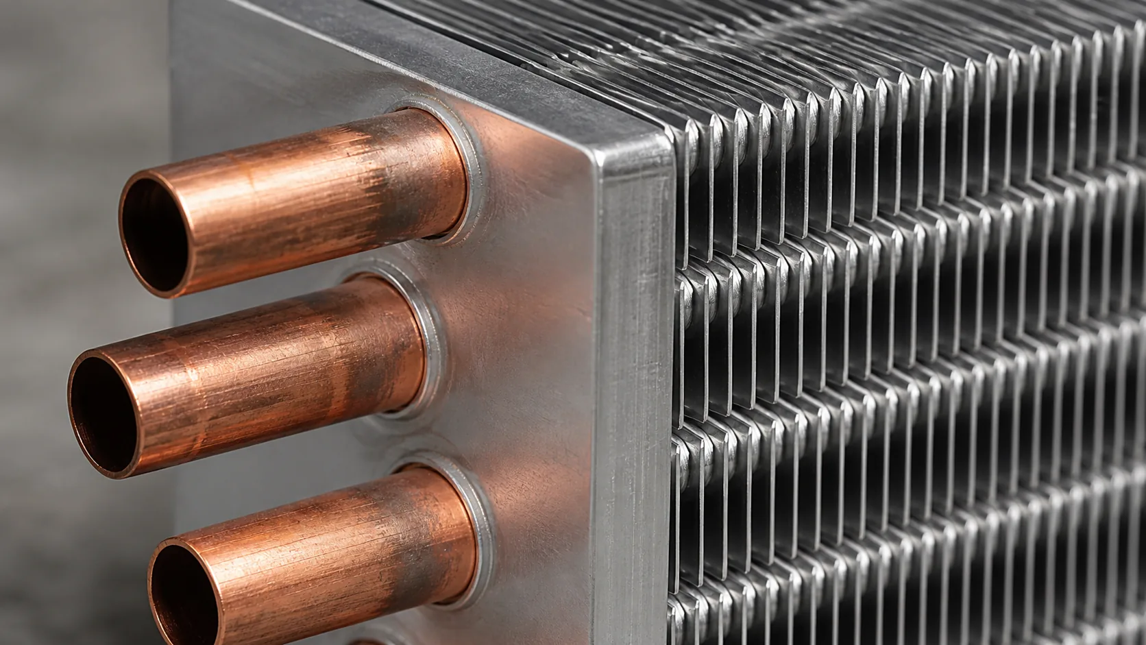
State tube material, tube outside diameter, wall thickness or applicable standard, fin material, fin thickness, fin type, fin pitch, and tube-to-fin bond. Copper tube with aluminum fins is common, but aluminum tube, copper fin, coated fin, stainless components, and microchannel construction may be suitable in other applications.
Header and return-bend materials
Include header material, return-bend geometry, connection material, braze alloy requirements, and any heat-treatment or cleaning requirement. If the supplier is expected to use an equivalent material, define the acceptance basis. “Equivalent” should mean equivalent pressure, corrosion, joining, thermal, and service performance, not only a similar appearance.
Frame, casing and coating
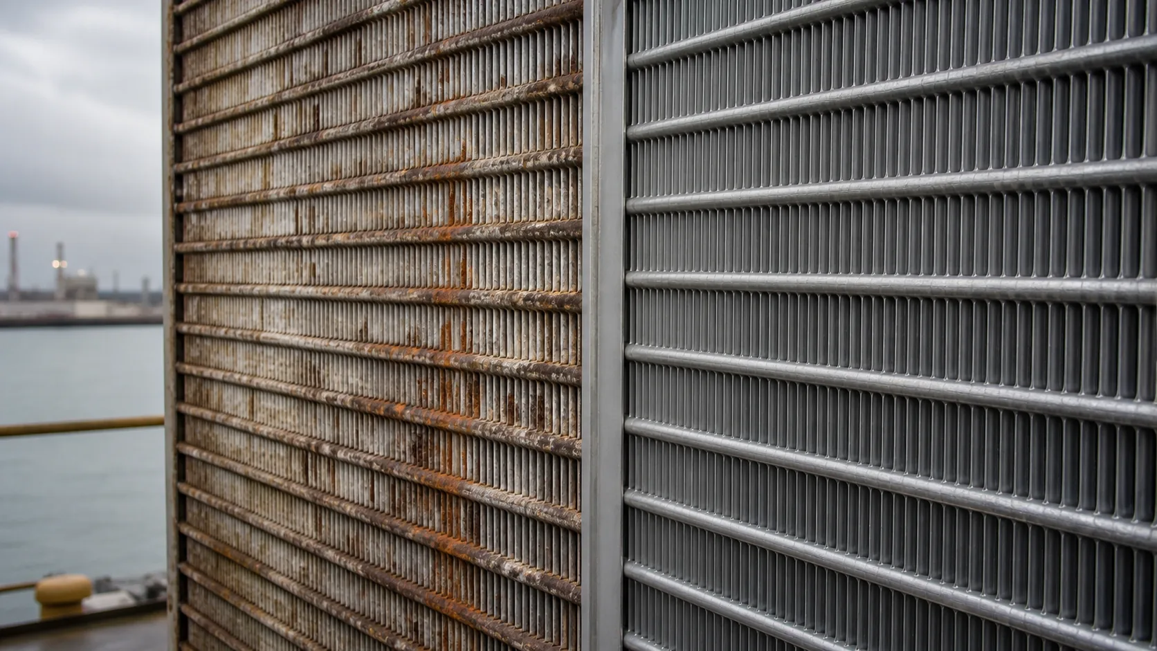
State frame and casing material, finish, drain or rain management, lifting points, fasteners, vibration isolators, and service panels. For outdoor or coastal service, describe salt, dust, grease, chemical vapor, humidity, and washdown exposure. Coating selection should name the surface, preparation, coating type, thickness or process control, curing, and inspection method.
The separate commercial refrigeration coil coating guide can support the corrosion portion of the review. Keep coating requirements in the specification instead of adding “anti-corrosion” as an undefined commercial phrase.
Circuiting, connections and pressure drop
Circuiting must match the refrigerant flow
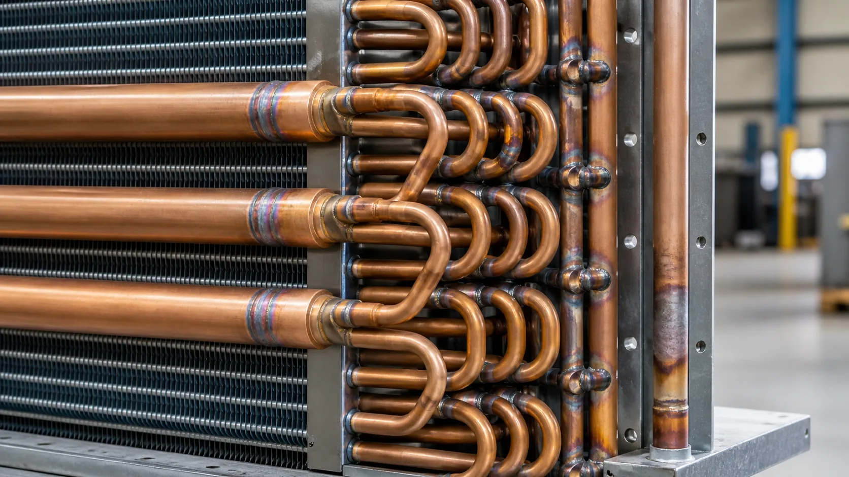
The number of circuits, circuit length, parallel paths, header size, and outlet arrangement affect refrigerant velocity, pressure drop, oil return, distribution, and subcooling. Require a circuiting sketch or drawing. A coil with the same face dimensions can behave differently when the circuit arrangement changes.
State all connection geometry
Include inlet and outlet tube outside diameters, connection orientation, center-to-center dimensions, projection from the frame, brazing or flare requirement, service valve interface, and tolerance. For replacement or constrained OEM assemblies, show datum references and mounting holes on the same drawing as connections.
Ask for both refrigerant-side and air-side pressure drop
Refrigerant-side pressure drop affects condensing temperature, liquid delivery, and compressor work. Air-side pressure drop affects fan power and airflow. Require the test or calculation condition for each value. ASHRAE Chapter 39 identifies pressure-drop calculation as part of condenser design, not a post-purchase detail.
Microchannel versus fin-tube construction
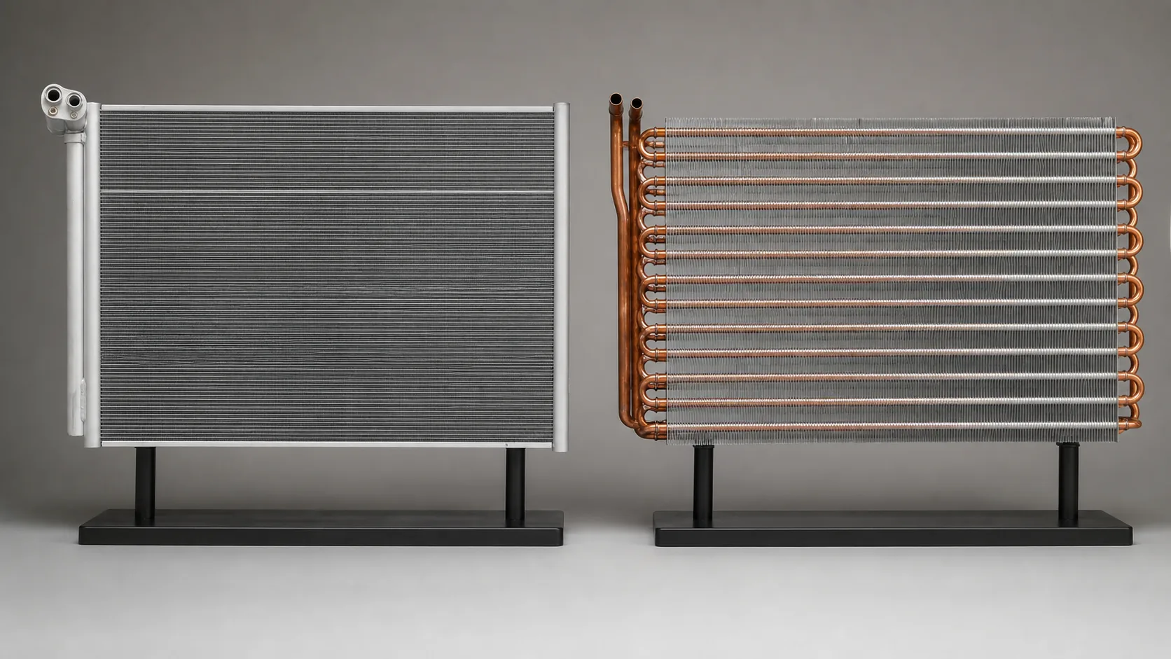
Microchannel and fin-tube coils can both be valid choices. The comparison should include thermal duty, pressure drop, refrigerant charge, joining, repair method, corrosion exposure, cleaning, weight, and supply risk.
| Specification area | Copper-tube aluminum-fin | Microchannel | Buyer decision |
|---|---|---|---|
| Tube geometry | Round tubes with return bends and headers | Multiport flat tubes with manifolds | Which geometry fits the available envelope and circuit layout? |
| Joining and repair | Brazed joints and replaceable connections may be familiar to service teams | Manifold and tube joints need process-specific repair controls | What repair method is acceptable in the installed market? |
| Air-side surface | Fin pitch, rows, tube pattern, and bond define surface | Flat multiport tubes and fins create a compact core | Is compactness worth the change in service and inspection method? |
| Corrosion review | Dissimilar-metal interfaces and coating may need attention | Aluminum surface and galvanic interfaces need their own review | What exposure and cleaning chemistry will the coil see? |
| Evidence | Circuit drawing, braze inspection, leak test, rating | Manifold design, leak test, rating, and handling controls | Which evidence must be included in first-article approval? |
Do not select one construction only because a catalog lists a higher nominal capacity. Use the same rating point, airflow, pressure-drop limit, and service assumptions for both options.
Drawing and dimensional specification fields
The drawing should allow a manufacturer and an incoming inspector to identify the same part. Include:
- overall length, height, depth, and allowed envelope
- face area, rows, tube pitch, fin pitch, and fin thickness
- tube and fin materials, header material, frame material, and coating callouts
- inlet and outlet connection size, orientation, and datum locations
- circuiting, header identification, flow direction, and subcooling path
- fan opening, guard, mounting holes, lifting points, and service clearances
- weld or braze notes, cleaning level, plugs, caps, and protection for shipping
- dimensional tolerances that affect fit, airflow, and connection alignment
- revision number, change description, approval signatures, and controlled file name
Avoid putting performance requirements only in a drawing note. Keep a rating schedule with the design conditions and link it to the drawing revision.
Inspection, testing and first-article evidence
Dimensional inspection
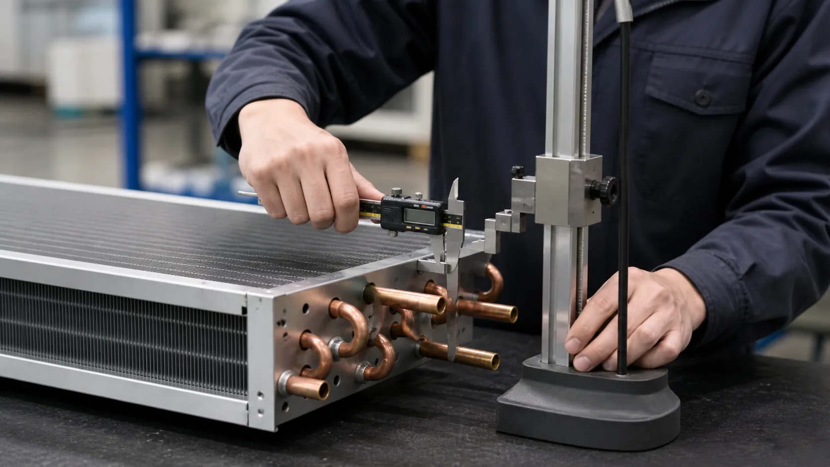
Inspect overall dimensions, tube projection, connection centers, mounting points, fin damage, header orientation, and coating coverage. Use a drawing with datum references and record the actual values. A photograph is useful evidence, but it does not replace a dimensional report.
Pressure and leak testing
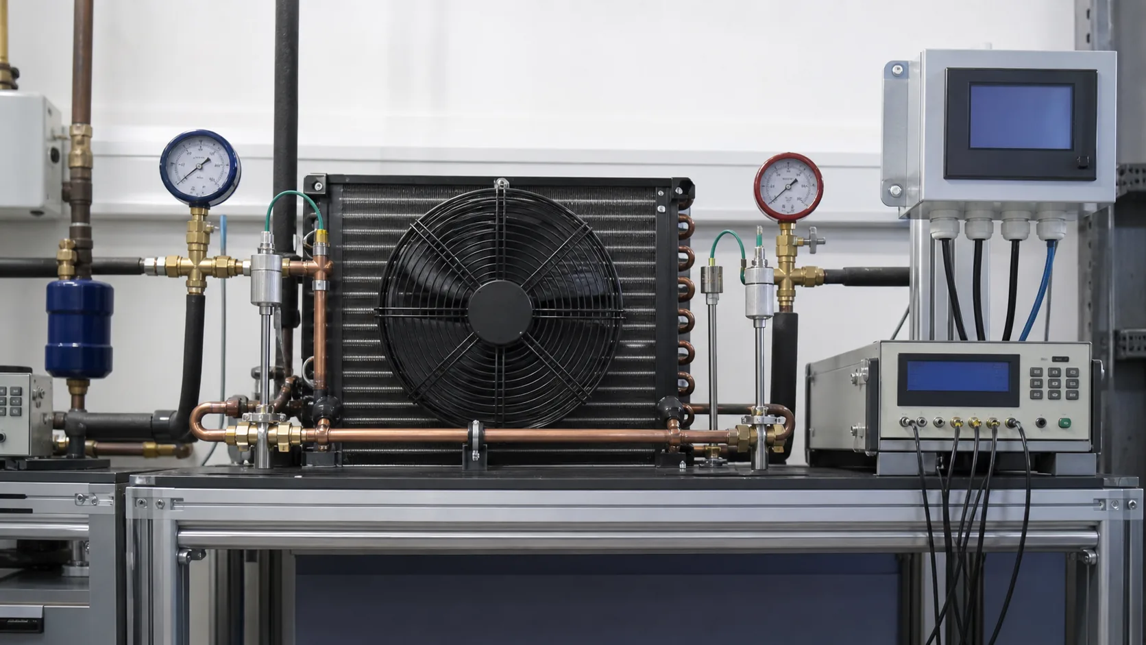
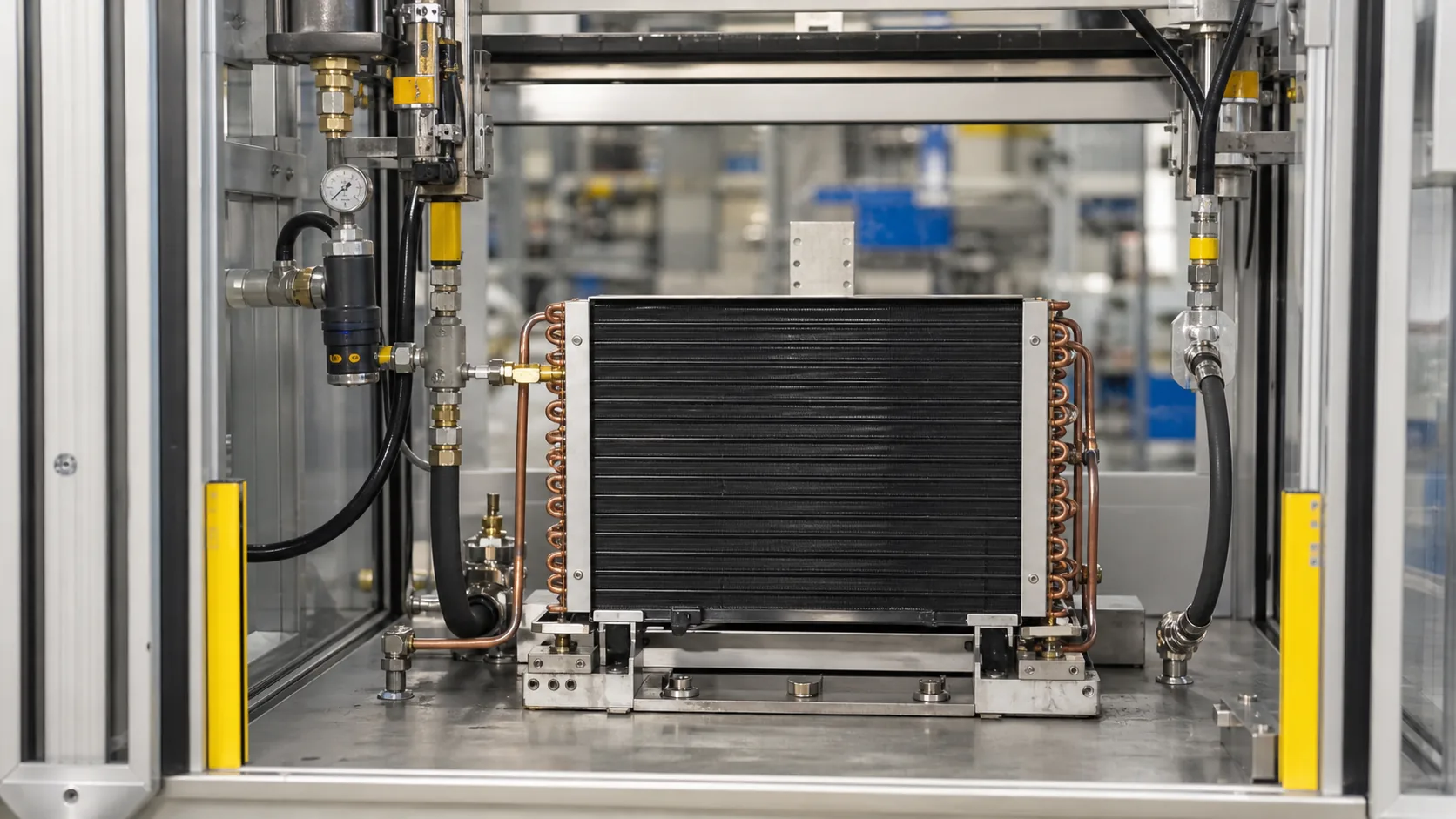
State the test medium, pressure, hold time, temperature, allowable pressure decay, and measurement resolution. Ask for a report that identifies the coil serial or batch, circuit tested, instrument ID, date, and result. If the customer will perform a field test, keep the factory acceptance test separate from the site procedure.
Thermal and airflow validation
For a prototype or first article, record total heat rejection, entering and leaving air, airflow, air-side pressure drop, refrigerant-side pressure drop, saturated condensing temperature, liquid outlet condition, fan input, and ambient. Use the same rating point as the quotation. If the coil is part of a complete unit, test the complete fan and cabinet arrangement as well.
AHRI scope check
AHRI 410 has a defined scope and exclusions. It does not automatically cover every refrigerant condenser, frosting condition, microchannel coil, or non-round tube design. Treat a standard reference as a scope question, not as a blanket certification claim.
PPAP, change control and supplier response
Request a complete technical submission
For an OEM program, ask for a signed data sheet, controlled drawing, material declarations, process flow, inspection plan, pressure-test record, thermal test method, packaging plan, and deviation list. Mark any field that is a supplier assumption. The buyer can then accept, reject, or resolve each assumption before tooling or production release.
Control changes after approval
Changing tube material, fin pitch, coating, header, circuiting, braze alloy, fan, or supplier process can change the released performance. Require written approval before a change enters production. Keep old and new drawing revisions attached to the change record.

OEM condenser coil specification checklist
Use this table as the minimum request package. Add product-specific fields for the equipment and market.
| Field group | Required information | Evidence to request |
|---|---|---|
| System duty | Total heat rejection, refrigerant, evaporating and condensing conditions, liquid outlet condition | Rating sheet with assumptions and units |
| Air side | Entering air, airflow, face velocity, pressure drop, fan curve, clearances | Air-side rating and installation layout |
| Refrigerant side | Design pressure, test pressure, circuits, tube size, connections, pressure drop | Circuit drawing and pressure-test method |
| Materials | Tube, fin, header, frame, coating, braze alloy, fasteners | Material callout, declaration, and coating controls |
| Geometry | Overall envelope, rows, fin pitch, datums, mounting, service side | Controlled 2D drawing and 3D model if needed |
| Quality | Dimensional inspection, leak test, thermal test, packaging, traceability | First-article report, test record, inspection plan |
| Change control | Revision process, deviation handling, approved supplier and sub-tier controls | PPAP or equivalent approval pack |
RFQ response fields buyers should compare
Ask each supplier to answer the same fields. A comparable response should show what is included and where engineering review is still required.
| Supplier response | Why it matters |
|---|---|
| Coil model, drawing revision, and quoted scope | Prevents a coil-only quote from being compared with a finished condenser |
| Capacity at the buyer rating point | Confirms that the number is not based on a different TD or airflow |
| Air-side and refrigerant-side pressure drop | Shows fan and compressor-side implications |
| Materials, coating, and joining method | Makes durability and process assumptions visible |
| Prototype, tooling, MOQ, and lead-time assumptions | Separates sample approval from repeat production planning |
| Test reports, deviations, and warranty boundary | Gives quality and procurement teams an approval path |
Send a drawing-led condenser coil inquiry to Domi
Include the rating point, refrigerant, design pressure, airflow, installation envelope, connection sketch, materials, corrosion exposure, quantity, and required evidence. If the coil is a replacement, add nameplate data, photographs, measurements, and the existing test conditions. Domi can review the missing inputs before preparing a custom quotation through the custom coil fabrication service. For a repeat OEM program, include annual demand, release pattern, sample approval, and change-control expectations.
Frequently asked questions
What is the most important field in an OEM condenser coil specification?
The rating condition is the first gate. State total heat rejection, refrigerant, entering air temperature, saturated condensing condition, airflow, and liquid outlet requirement. Without those inputs, a capacity or price comparison is not meaningful.
Should an OEM specification state total heat rejection or refrigeration capacity?
State total heat rejection for the condenser, then show how it relates to the compressor and evaporator duty. Refrigeration capacity alone does not describe the heat the condenser must reject because compressor input also enters the high-side balance.
What pressure-drop data should a condenser supplier provide?
Request refrigerant-side pressure drop and air-side pressure drop at the quoted rating point. Ask for the calculation or test condition, circuiting, airflow, and any allowable operating range used for the result.
Is copper tube and aluminum fin enough to define a condenser coil?
No. The specification still needs tube size and wall, fin pitch and thickness, rows, circuiting, headers, connections, frame, coating, pressure, capacity, airflow, and test evidence. The same material pair can be built into very different coils.
When should an OEM compare microchannel and fin-tube coils?
Compare them when the equipment envelope, charge, weight, corrosion exposure, service method, or supply strategy makes construction a real design choice. Use the same rating point and pressure-drop limits, then review repair and inspection requirements before approval.
What changes require a new condenser coil approval?
Treat changes to tube or fin material, fin pitch, circuiting, headers, coating, braze alloy, connections, fan arrangement, and manufacturing location as approval triggers. The responsible engineer should decide whether a re-rate, sample, or full first-article test is required.