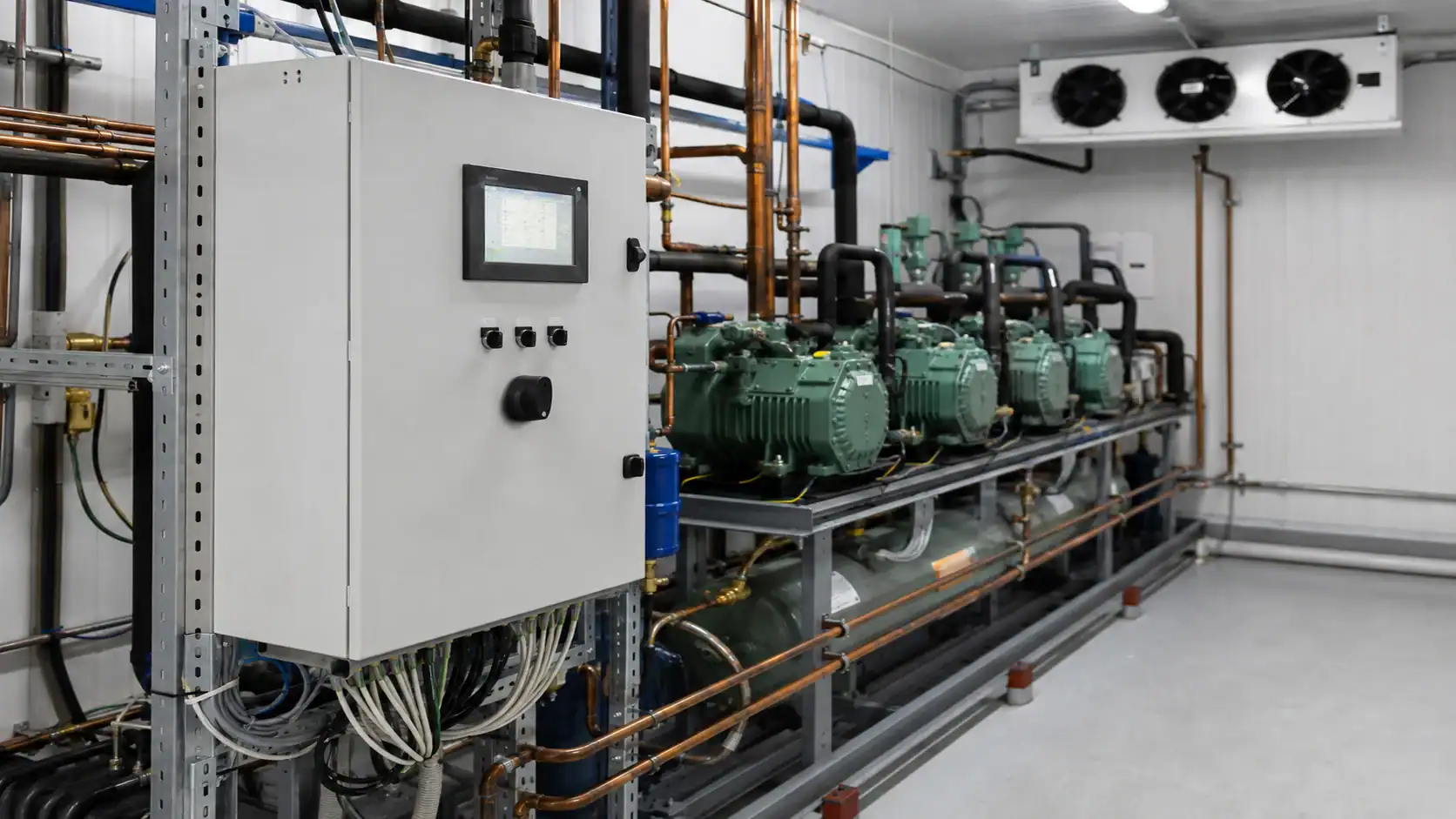
A refrigeration controller measures temperature and equipment status, then coordinates the compressor, evaporator fans, defrost, alarms and other outputs. The correct model depends on the room or process temperature, sensor arrangement, defrost method, load-control range, electrical outputs, communication needs and the refrigeration coils it must operate. For an OEM or replacement project, select the controller as part of the complete system rather than as an isolated thermostat.
What is a refrigeration controller?
A refrigeration controller is the decision layer between sensors and refrigeration equipment. It reads one or more temperature or pressure inputs, compares those readings with a setpoint and differential, and switches or modulates outputs. Depending on the design, outputs may operate a compressor contactor, condenser fan, evaporator fan, electric heater, hot-gas valve, liquid-line solenoid, door alarm, light or communication gateway.
The controller does not create cooling capacity. It protects and directs the compressor, evaporator, condenser and expansion device so those components operate in a predictable sequence. A controller with a good display can still be the wrong choice if its sensor range, relay rating, defrost logic or minimum compressor off-time does not match the equipment.
Most control decisions can be reduced to five questions:
- What variable must stay within limits: room air, product, process fluid, coil surface or pressure?
- How many sensors are needed to control, terminate defrost and detect a fault?
- Which loads must be switched or modulated, and what are their voltage and current ratings?
- What should happen during defrost, door opening, sensor failure, power recovery and a high-temperature alarm?
- How will an operator or building management system see the data and acknowledge an alarm?
Controller types and their practical limits
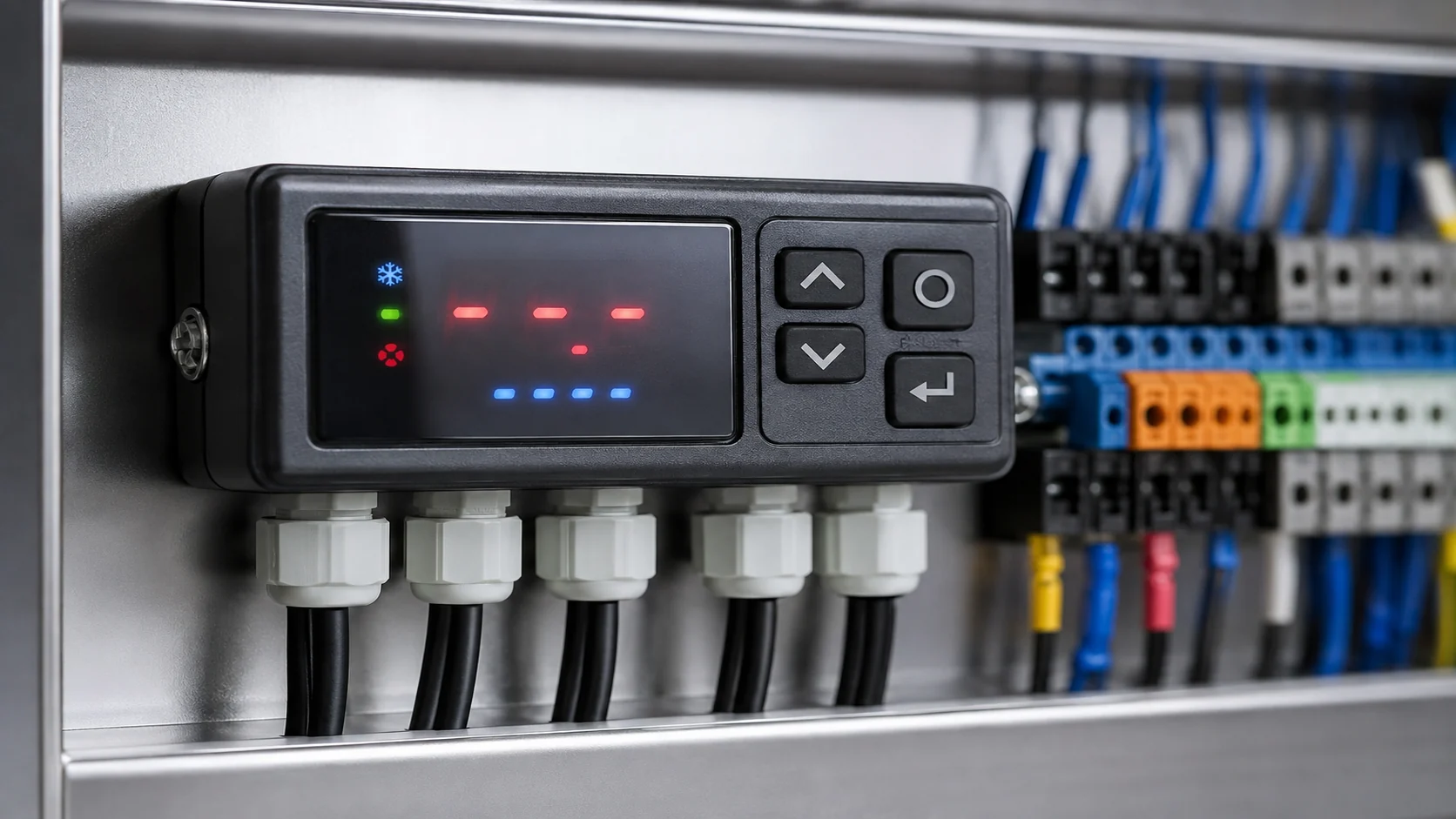
The first decision is architecture. A small display case may need one room sensor and a compressor relay. A freezer room or food-processing line may require several sensors, defrost termination, fan delay, alarms, logging and network communication.
| Controller type | Typical construction | Best fit | Limitation to check before purchase |
|---|---|---|---|
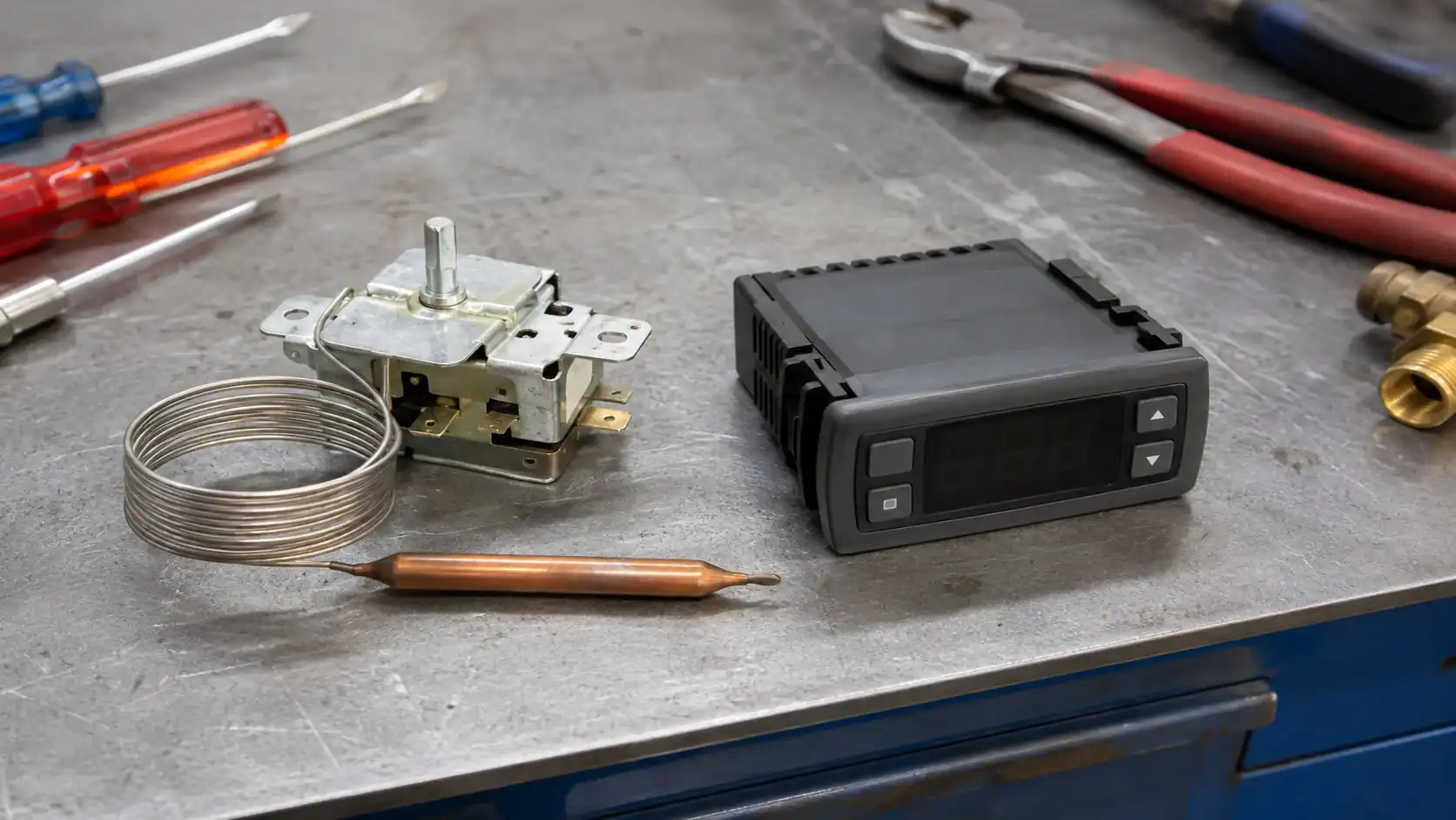
| Mechanical thermostat | Capillary tube and sensing bulb operate electrical contacts | Simple coolers, legacy equipment and basic replacement work | Limited alarm, logging, differential and communication functions |
| Electronic temperature controller | Microprocessor, probe inputs, relays and a local display | Walk-ins, reach-ins, beverage cases and compact condensing units | Confirm probe type, relay ratings, parameter access and restart protection |
| Multi-output refrigeration controller | Dedicated outputs for compressor, fans, defrost and alarms | Freezers, medium cold rooms and packaged systems | Confirm defrost termination, fan-delay logic and sensor-failure behavior |
| Rack or case controller | Controls a circuit or suction group and exchanges data with a supervisor | Supermarkets and distributed commercial systems | Verify network protocol, staging strategy and minimum-load stability |
| Facility or plant controller | Networked controller supervising many rooms, racks or process loops | Industrial cold storage and monitored food facilities | Confirm redundancy, cybersecurity, historian capacity and integration scope |
Mechanical controls remain useful when a simple circuit needs a robust, serviceable switch. They are a poor fit when the buyer needs a temperature history, adaptive defrost, remote alarm or coordinated compressor staging. Electronic controllers add those functions, but the additional parameters must be documented so a replacement does not silently change the operating sequence.
The Danfoss electronic temperature control range is an example of application-specific controller families. Use manufacturer documentation for the actual sensor, output and programming limits instead of copying a parameter list from another model.
Define the application before selecting a model
Temperature alone is not enough to choose a controller. The application determines the control sequence, alarm delay, sensor count and defrost method. Use the following ranges only as a planning screen, then confirm the product, process and local requirements.
| Application | Typical temperature band | Control functions normally required | Selection question |
|---|---|---|---|
| Beverage case or reach-in cooler | 34°F to 46°F | Room temperature, compressor cycle, fan control and door input | Is product temperature or air temperature the critical variable? |
| Walk-in cooler | 35°F to 40°F | Room sensor, evaporator sensor, compressor delay and high-temperature alarm | Does door traffic require a delayed alarm and recovery mode? |
| Walk-in freezer | -10°F to 10°F | Room and coil sensors, electric or hot-gas defrost, fan delay and alarm history | What ends defrost and how is a failed termination sensor handled? |
| Blast chiller or freezer | -40°F to 35°F | Multiple probes, pull-down stages, logging and recipe or batch inputs | Does the process require product-core measurement and a defined cycle? |
| Industrial cold store | -30°F to 20°F | Redundant sensors, rack coordination, remote alarms and data retention | What is the safe state if a network or sensor fails? |
| CO2 or cascade system | Application dependent | Pressure inputs, electronic expansion valve coordination and high-pressure logic | Are pressure transducers and relief interlocks inside the controller boundary? |
Write the application definition in the RFQ. Include room dimensions, product or process load, target temperature, allowable variation, door schedule, ambient conditions, defrost method, required recovery time and the number of refrigeration circuits. This prevents a controller marketed as “universal” from being applied outside its actual relay, sensor or temperature range.
Build a reliable temperature-control loop
Setpoint and differential
The setpoint is the desired control value. The differential, sometimes called hysteresis, is the amount of change that is allowed before the output changes state. A medium-temperature room might use a setpoint near 37°F with a 2°F to 4°F differential, but the final values depend on product tolerance, coil TD, loading and compressor limits. Do not copy these numbers into a freezer or process application without a validated sequence.
Set a minimum compressor on-time and off-time when the compressor manufacturer requires it. A narrow differential with a poorly located sensor can create repeated starts. A wide differential can produce large product swings and a long recovery after a door opening. The controller should expose these parameters clearly and record who changed them.
Sensor location and type
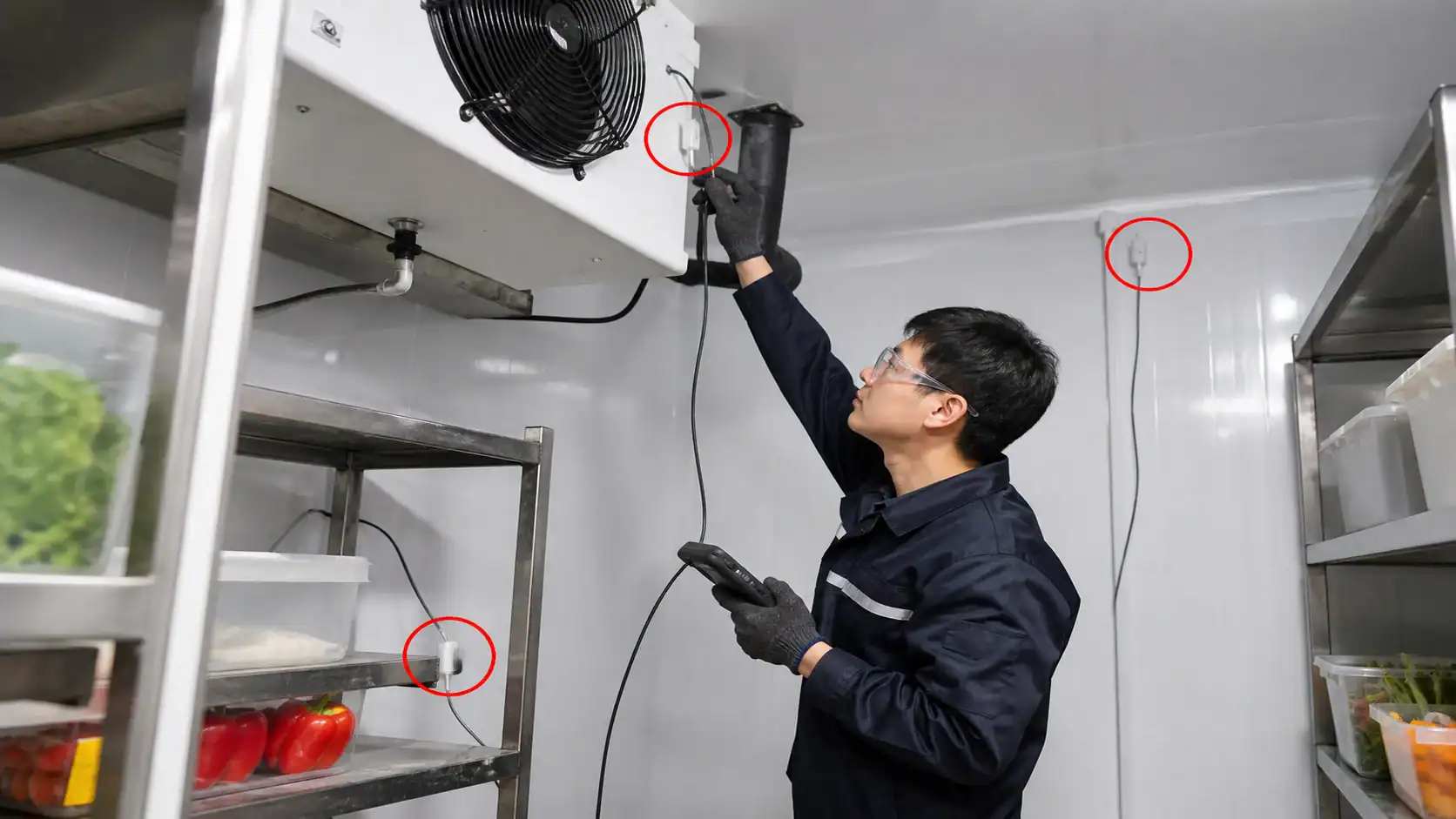
Use a return-air or representative room location for room control. Keep the sensor out of the direct evaporator discharge jet, away from a warm door frame and clear of a product surface that does not represent the room. Add an evaporator sensor when fan delay or defrost termination depends on coil temperature. Add a product or core probe when the product, not the air, is the controlled variable.
Common sensor choices include NTC thermistors for compact equipment, PTC probes for selected controller families, and PT100 or PT1000 sensors where industrial accuracy and longer cable runs justify the extra cost. A 4 mA to 20 mA transmitter may be appropriate for a larger plant or a pressure measurement. The controller and probe must share the same curve, connector and calibration method.
Sensor-failure behavior
Ask what happens when a sensor is open, shorted, out of range or disconnected. A safe response might stop the compressor, run a timed fallback, hold the last known state for a limited period or transfer control to a redundant probe. The correct response depends on the application. A freezer protecting food cannot use the same fallback as a process line where an immediate shutdown could damage material.
Defrost control is a controller decision
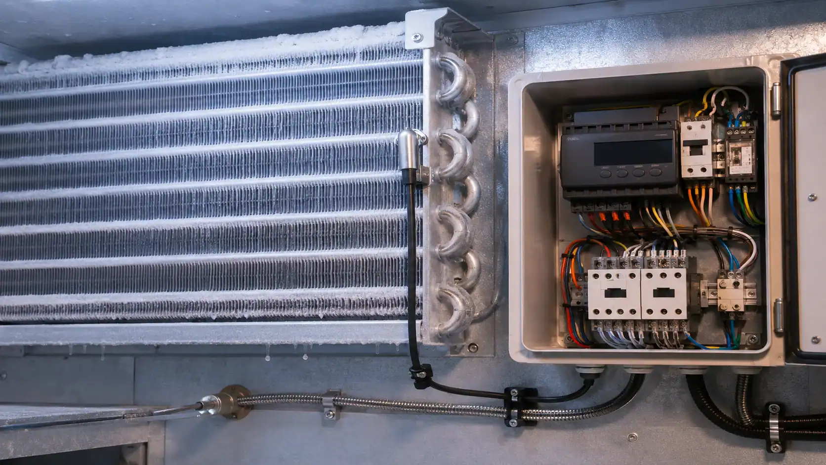
Frost reduces airflow and heat transfer on a low-temperature evaporator. The controller must start defrost at a defined time, demand or interval, terminate it with a sensor or time limit, and delay the fans until liquid water is controlled. The Domi refrigeration defrost methods guide explains why electric, hot-gas and off-cycle methods require different component and control sequences.
Off-cycle defrost
Off-cycle defrost stops refrigeration and allows the coil to warm naturally. It is often suitable for medium-temperature coolers where the coil surface remains above freezing for much of the cycle. The controller still needs a fan strategy, condensate protection and a recovery delay. If the room is humid or the door load is high, off-cycle may not remove frost reliably.
Electric defrost
Electric defrost needs a heater output with an appropriate contactor or solid-state interface, a coil sensor for termination and a maximum defrost time. The controller should stop the compressor, sequence the fans, energize the heater, terminate on coil temperature and run a drip period before refrigeration resumes. Include heater current and voltage in the RFQ; a controller relay that is adequate for a small heater may be unsuitable for a larger bank.
Hot-gas defrost
Hot-gas defrost uses valves and pressure relationships to send hot discharge gas through the evaporator. The controller must coordinate liquid-line, hot-gas, suction and fan outputs, with an interlock that prevents an unsafe valve combination. Confirm the required pressure inputs and fail-safe state with the refrigeration designer. Do not treat hot-gas defrost as an electric-defrost parameter change.
Adaptive defrost can reduce unnecessary cycles when the controller has reliable coil and room information. The Danfoss adaptive-defrost explanation describes the principle, but the actual savings and termination settings still depend on the evaporator, fin spacing, airflow and door load.
Coordinate compressors, fans and coils
A controller should make the entire refrigeration circuit behave as one machine. During a normal cooling cycle, it may open a liquid-line solenoid, start the compressor after the required delay, enable the evaporator fan and monitor the room. During pump-down or a fault, it may close the solenoid, stop the compressor, hold the fan or raise an alarm. During defrost, it must use a different sequence.
The Domi refrigeration compressor guide covers compressor capacity and operating-envelope inputs that should be agreed before controller parameters are written. The controller cannot correct an evaporator with inadequate airflow, a condenser with excessive head pressure or a compressor selected outside its envelope.
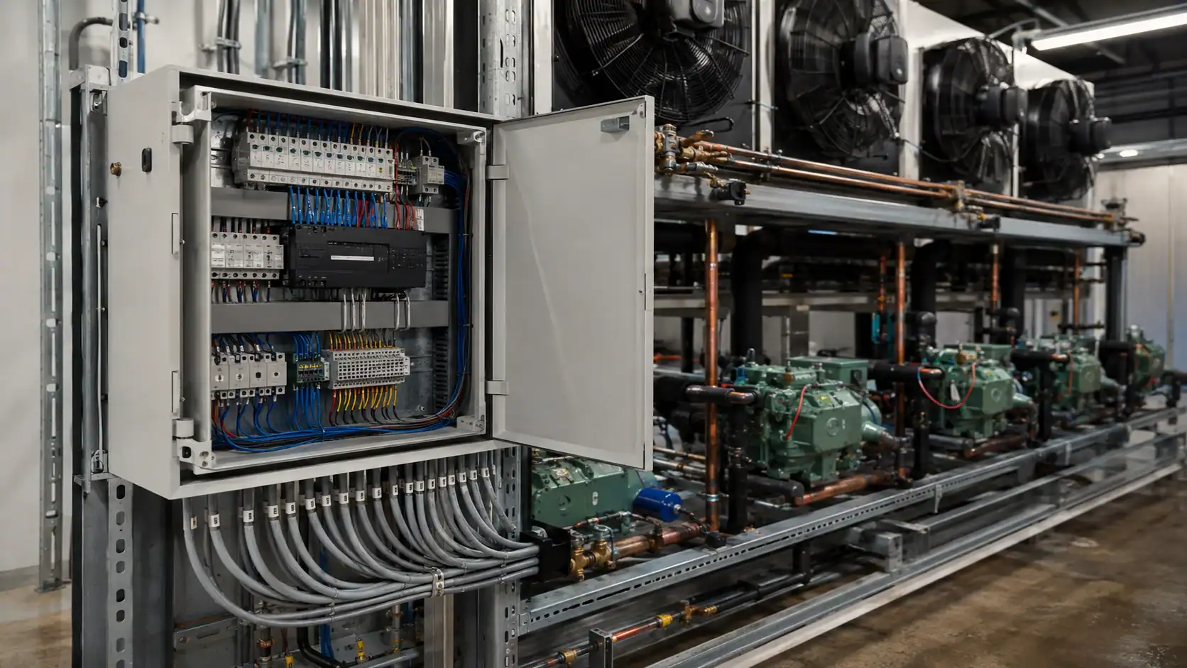
For an evaporator fan, define whether the fan runs continuously, cycles with the compressor, stops during defrost or restarts after a drip delay. For a condenser fan, define head-pressure control, minimum speed and cold-ambient behavior. For an electronic expansion valve, specify the pressure and temperature inputs, superheat target, valve driver and fallback state. These details belong in the I/O list and sequence of operation, not only in a controller product name.
Alarms, records and remote visibility
Alarm design should distinguish a short event from a real loss of control. A high-temperature alarm may need a delay after door opening, loading or defrost. A sensor alarm should usually act immediately because the controller no longer knows the controlled value. A compressor overload, high discharge temperature, condenser high pressure, fan failure or liquid-level fault may require a shutdown and a latched alarm.
At minimum, define the alarm threshold, delay, reset method, relay output, local indication, remote destination and event-history retention. If the site follows a food-safety or HACCP plan, confirm how temperature records are exported and how time stamps are synchronized. Avoid claiming compliance from a controller label alone; the site procedure, calibration and record retention determine whether the monitoring program is acceptable.
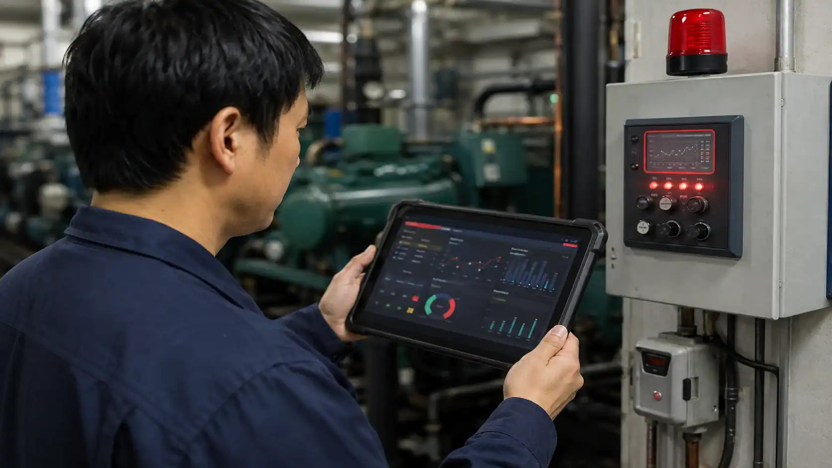
For a networked installation, document the communication protocol, address plan, time source, user roles and loss-of-communication behavior. A remote alarm that disappears when the network is offline is not a robust alarm strategy. Provide a local fallback indication and a clear escalation path for the operator.
Special considerations for freezers and CO2 systems
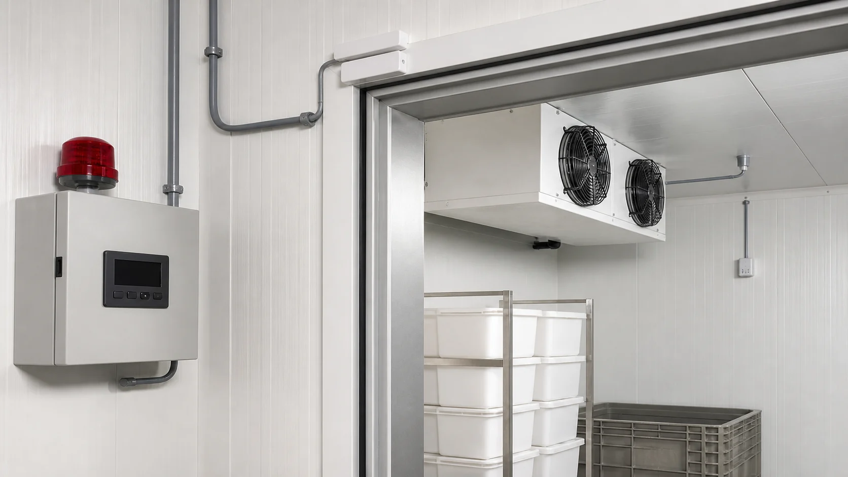
Freezers have greater frost and defrost demands than coolers. The controller needs a coil sensor that can terminate defrost, a fan delay that prevents warm humid air from being blown across the product, and an alarm delay that accounts for the recovery period. The sensor cable, heater contactor, enclosure rating and drain protection should be reviewed as part of the freezer package.
CO2 systems add pressure and transcritical or cascade control considerations. High-side pressure, gas cooler outlet temperature, receiver pressure and electronic expansion valve position may all affect the sequence. Use rated pressure transducers, wiring and enclosures, and define the safe state for a lost pressure signal. A controller designed for a low-pressure HFC condensing unit should not be assumed suitable for a high-pressure CO2 rack.
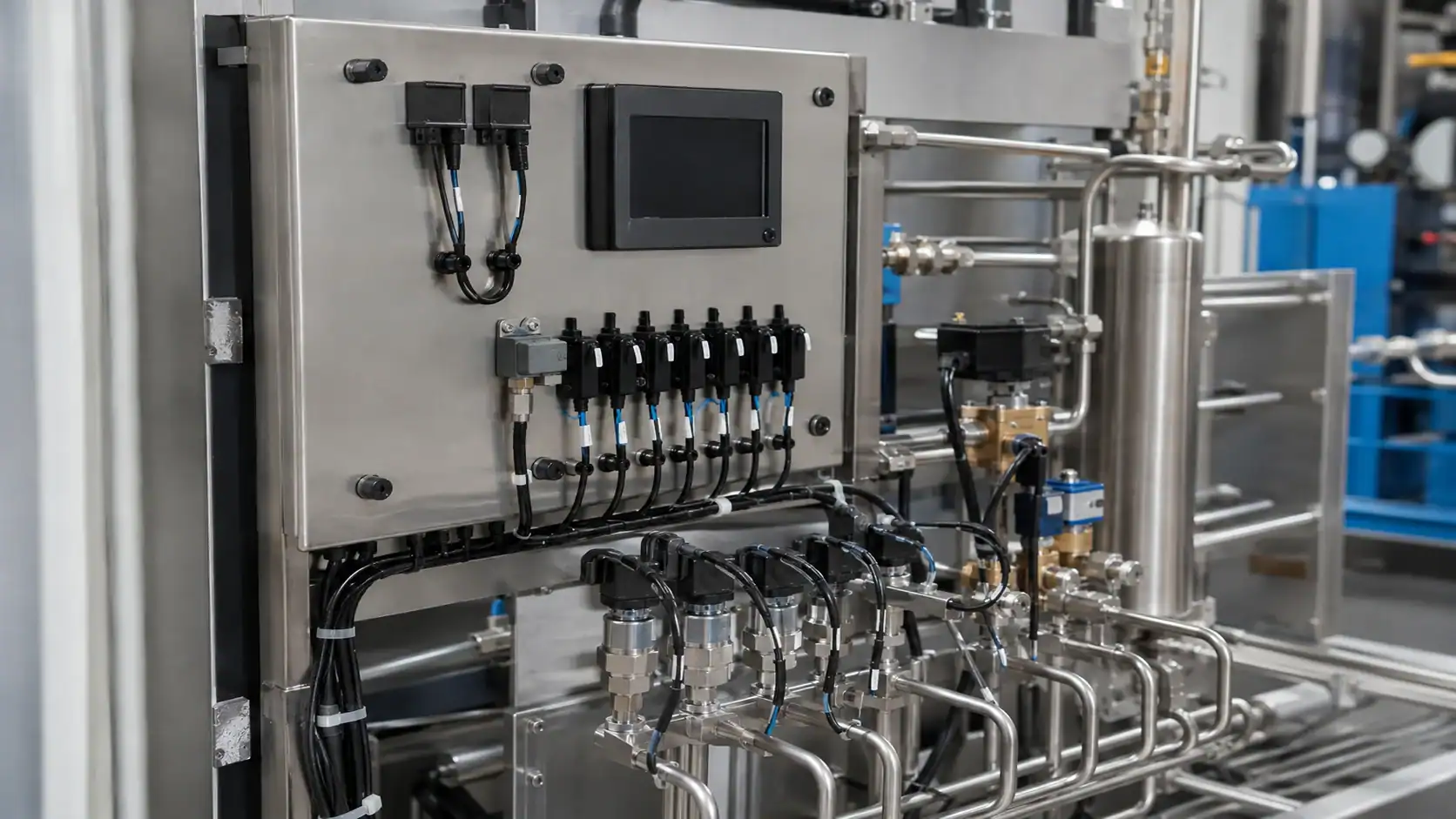
Refrigeration controller RFQ checklist
Send the same information to every supplier so that controller quotes can be compared on function rather than on a display size or number of buttons.
| RFQ field | What to state | Why it matters |
|---|---|---|
| Application and temperature | Cooler, freezer, process, cascade or CO2; normal and limit temperatures | Defines sensor range, alarms and defrost strategy |
| Sensors | Type, quantity, cable length, location and calibration requirement | Prevents incompatible probes and poor control placement |
| Outputs | Compressor, fans, defrost, valves, heaters, alarms and lighting | Determines relay, contactor and interlock requirements |
| Defrost | Off-cycle, electric, hot gas, interval or demand; termination rule | Changes the sequence, sensors, outputs and recovery timing |
| Compressor protection | Minimum on or off time, pump-down, overload input and restart delay | Protects the compressor from short cycling and unsafe starts |
| Fan sequence | Continuous, cycling, defrost stop, drip delay and speed control | Affects temperature uniformity, frost and energy use |
| Alarms and history | Thresholds, delays, latching, acknowledgment and retention | Turns a controller into an operational monitoring tool |
| Electrical service | Voltage, phase, frequency, input protection and enclosure | Prevents relay, power-supply and installation mismatches |
| Communications | Protocol, gateway, remote access, time source and user roles | Supports BMS, SCADA or plant monitoring integration |
| Documentation | Wiring diagram, I/O list, parameter backup, manuals and change log | Makes commissioning and future replacement repeatable |
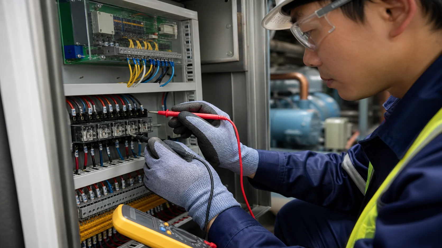
Ask for a completed I/O list and a sequence-of-operation document with the quote. Request the controller model, firmware or parameter revision, compatible probes, relay derating, enclosure dimensions, spare parts and lead time. If the controller is part of an OEM appliance, include the coil drawing, compressor model, valve selection and electrical schematic so the supplier can validate the complete interface.
Commissioning and replacement checks
Before energizing a new or replacement controller, compare the wiring to the approved drawing. Verify probe identity, polarity where applicable, input scaling, relay common connections, contactor coils, fuse sizes, door switches and emergency stops. Do not assume that terminals with the same number have the same function on a different controller family.
Commissioning should test normal cooling, pump-down, defrost start, defrost termination, fan delay, alarm delay, power recovery and sensor failure. Record actual readings rather than only checking whether an output light turns on.
| Commissioning test | Evidence to record | Pass condition |
|---|---|---|
| Sensor verification | Reference thermometer, controller reading, location and calibration offset | Reading is within the approved tolerance at the point of control |
| Cooling cycle | Setpoint, differential, suction condition, compressor state and fan state | Sequence starts and stops without short cycling |
| Defrost cycle | Start trigger, heater or valve output, coil temperature and termination time | Defrost terminates by the approved rule and fans restart after drip delay |
| Alarm test | Simulated high temperature, sensor fault, overload or door event | Alarm appears locally and remotely with the correct delay and reset behavior |
| Power recovery | Controller state, compressor delay and alarm behavior after interruption | Restart is controlled and no unsafe simultaneous start occurs |
| Communications | Address, time stamp, trend and loss-of-link response | Data is visible and the local fallback remains safe |
| Documentation handoff | Parameter backup, wiring diagram, change log and training record | Site team can restore settings and identify each input and output |
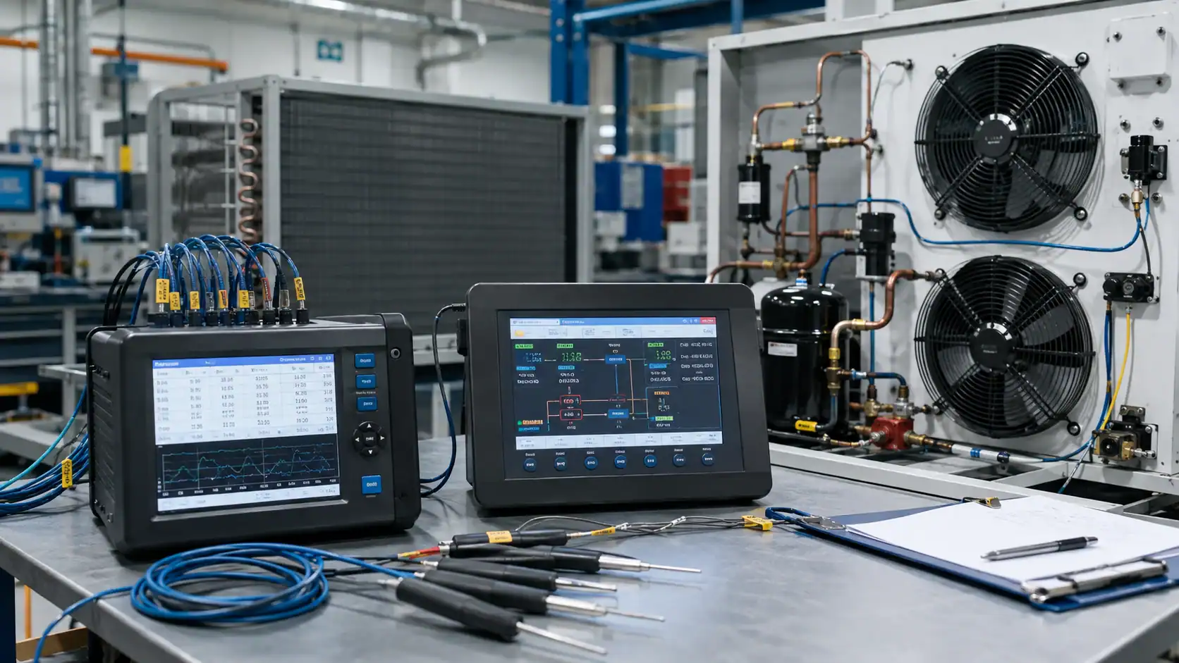
For a replacement, photograph the old wiring, record every terminal and save the old parameter set before removing the controller. Confirm the new sensor curve, output rating and defrost method before loading parameters. A physically compatible front panel does not prove that the control sequence is compatible.
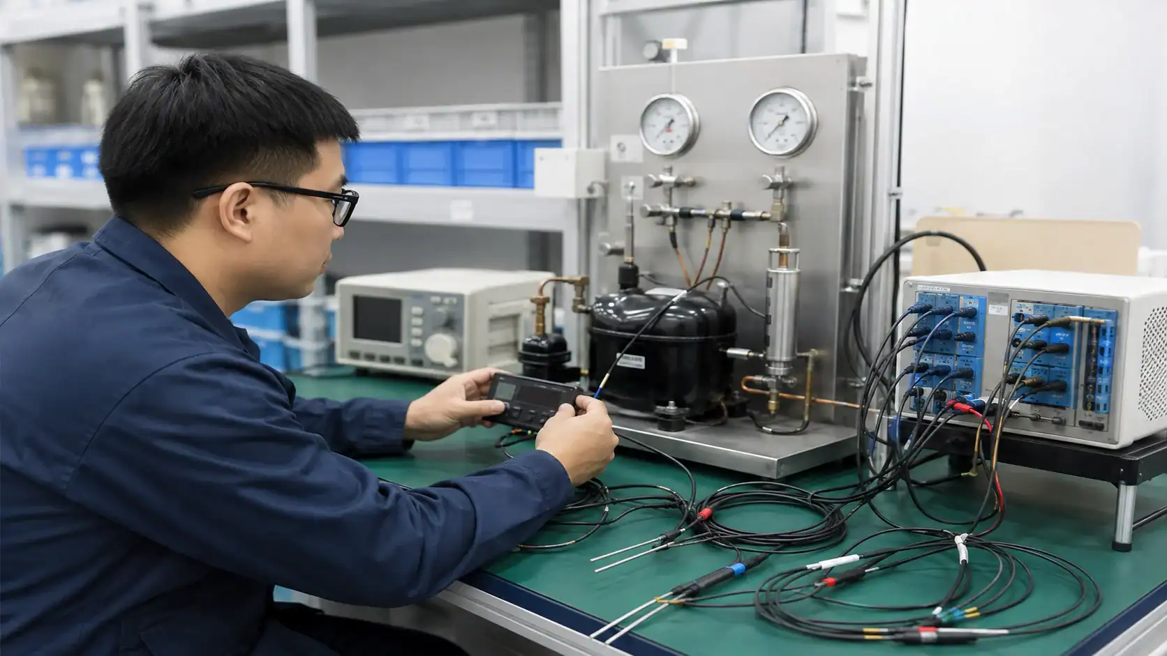
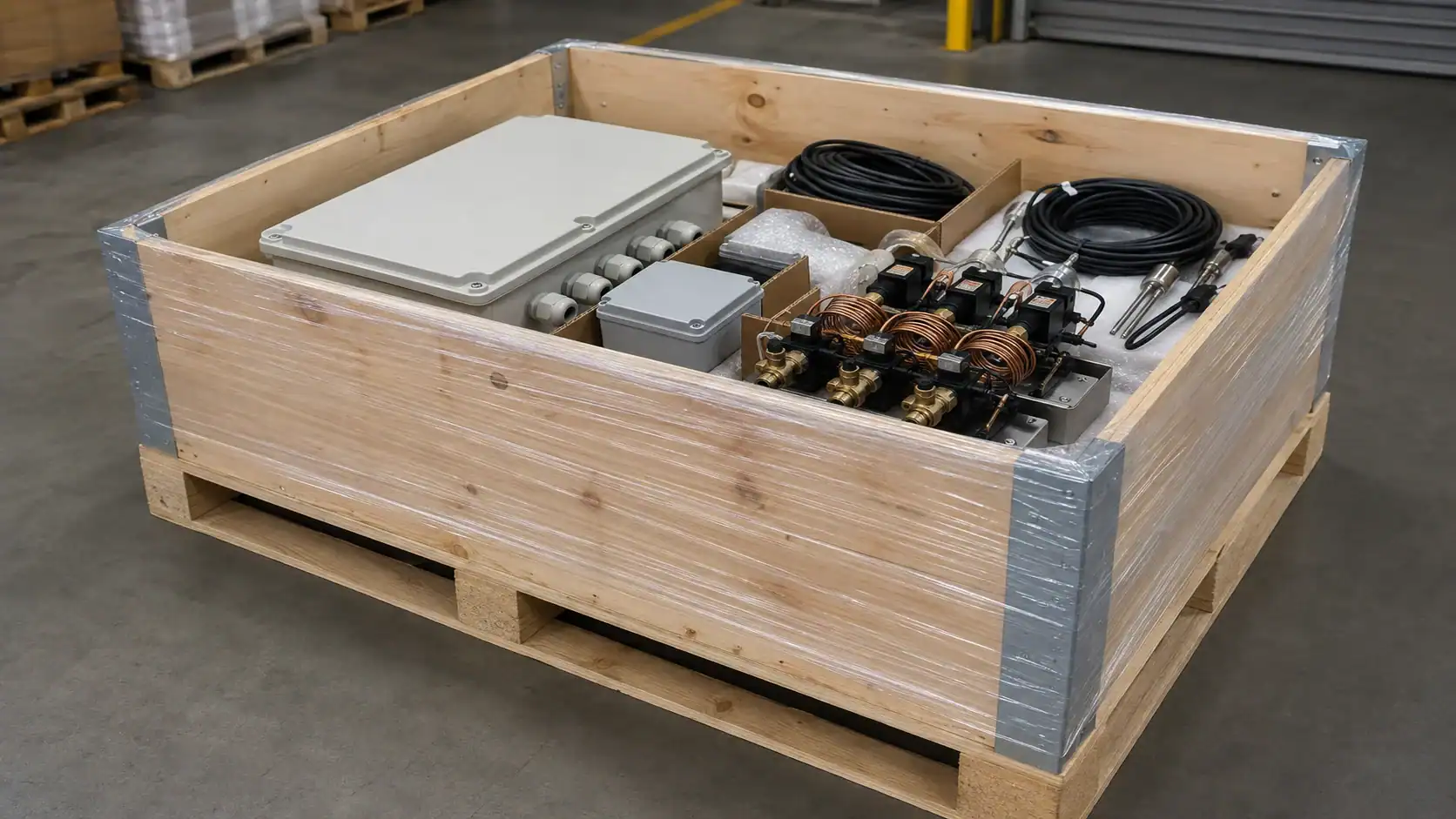
Factory acceptance should include an electrical I/O check, sensor simulation, alarm simulation, communication test and a review of the parameter backup. If a matched evaporator or condenser is supplied, keep the same revision identifier on the controller configuration, coil drawing and packing list.
Frequently asked questions
What does a refrigeration controller control?
A refrigeration controller can control the compressor, evaporator fans, condenser fans, defrost heaters or valves, liquid-line solenoid, alarms and communications. The exact outputs depend on the model and the system sequence. It reads temperature, pressure or status inputs and changes those outputs according to setpoints, differentials, timers and safety interlocks.
How do I choose a refrigeration controller?
Start with the application temperature, refrigerant system, defrost method, sensor count, output list and alarm requirements. Then check voltage, relay ratings, sensor type, enclosure, communication protocol, parameter access and minimum compressor on or off time. Require a wiring diagram and sequence of operation, not only a controller part number.
What sensors does a walk-in cooler controller need?
A basic walk-in cooler normally needs a representative room or return-air sensor. Add an evaporator sensor when fan control or defrost protection needs coil temperature, and add a door switch or product probe when the operation requires it. Place the control sensor away from direct discharge air, doors and unrepresentative hot or cold surfaces.
How does a refrigeration controller manage defrost?
It starts defrost by a schedule, interval or demand rule, stops normal refrigeration, energizes an electric heater or hot-gas valve when applicable, and ends defrost using a coil-temperature sensor or a maximum time limit. It then applies a drip and fan-delay period before cooling resumes. The sequence must match the evaporator, defrost hardware and refrigerant system.
What is the difference between a thermostat and a refrigeration controller?
A thermostat usually changes one temperature-controlled contact. A refrigeration controller can coordinate several outputs, multiple sensors, defrost, alarms, data logging and network communication. A thermostat may be a suitable low-cost replacement for a simple legacy circuit, but it cannot replace those functions without additional hardware and a validated sequence.
What information should I send for an OEM controller quote?
Send the application and temperature range, refrigerant, compressor and coil models, defrost method, sensor types and locations, output list, voltage, communication protocol, alarm requirements, enclosure dimensions, wiring diagram and required delivery date. Include a nameplate photo or parameter backup for a replacement. Mark unknown values for confirmation instead of assuming compatibility.
Related Articles
Send a controller and coil RFQ
Domi can review the evaporator or condenser side of a controlled refrigeration package from your I/O list, drawing, sample, nameplate or failed component. Send the refrigerant, temperature range, airflow, circuiting, sensor locations, connection layout and required delivery date through the Domi technical inquiry page. The team can confirm coil construction, testing and packaging requirements while your controls supplier validates the controller sequence.