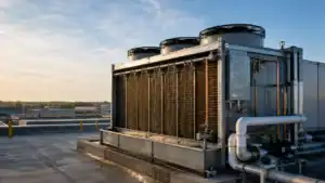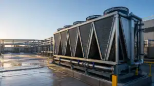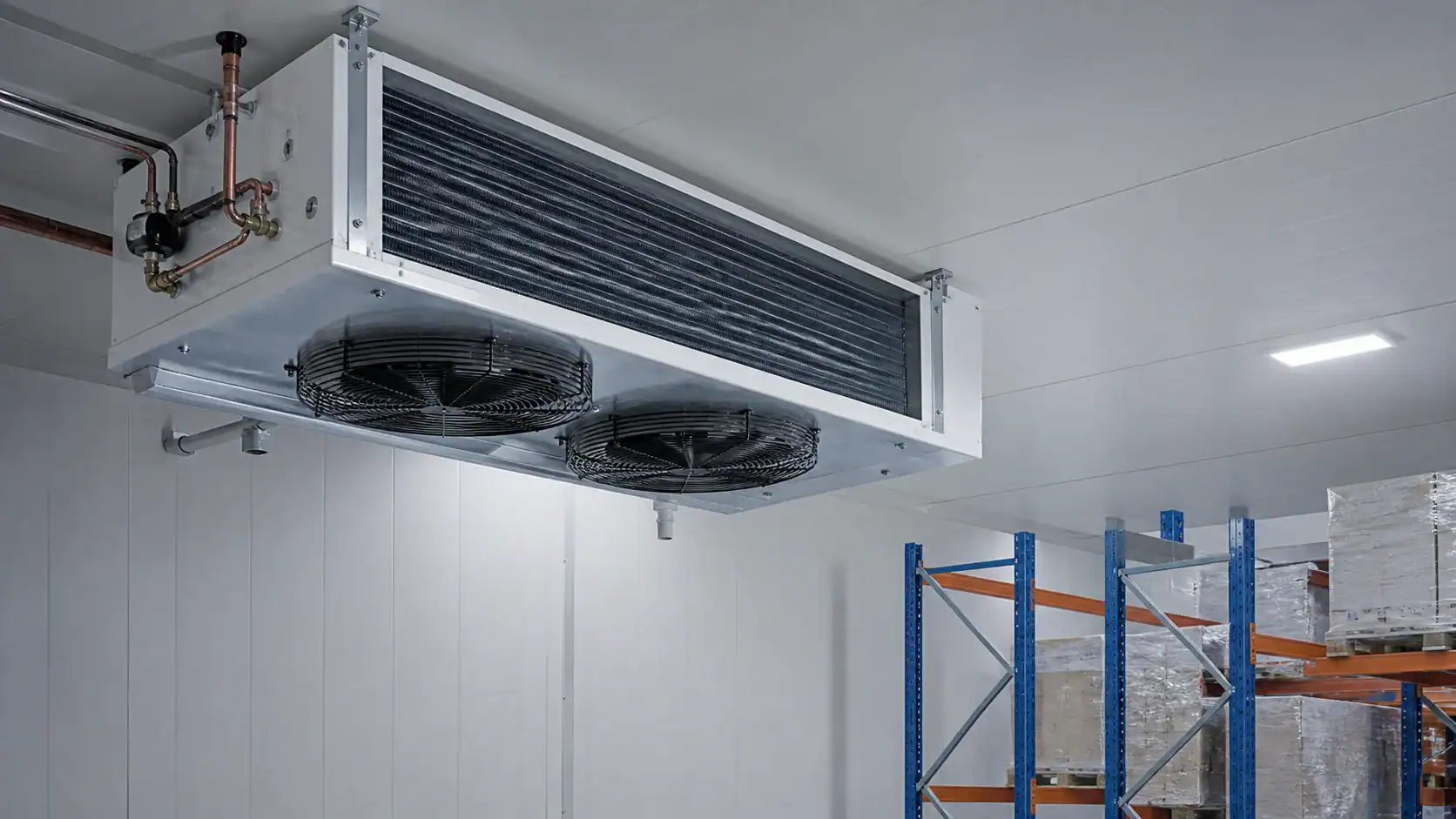
A unit cooler is the indoor evaporator assembly that removes heat from a refrigerated room and returns conditioned air to the space. A sound selection starts with the room load, product, temperature, air path, coil condition, defrost method, refrigerant, drain, mounting, and service plan. A catalogue capacity alone cannot show whether the cooler will reach the far rack, survive frost, or fit the released equipment drawing.
This guide is for cold-storage operators, OEM engineers, contractors, distributors, and procurement teams comparing commercial or industrial unit coolers. It treats the unit cooler as a complete air-side and refrigerant-side interface. The final capacity, pressure rating, materials, fan package, controls, and commercial terms must be confirmed for the actual project.
What is a unit cooler?
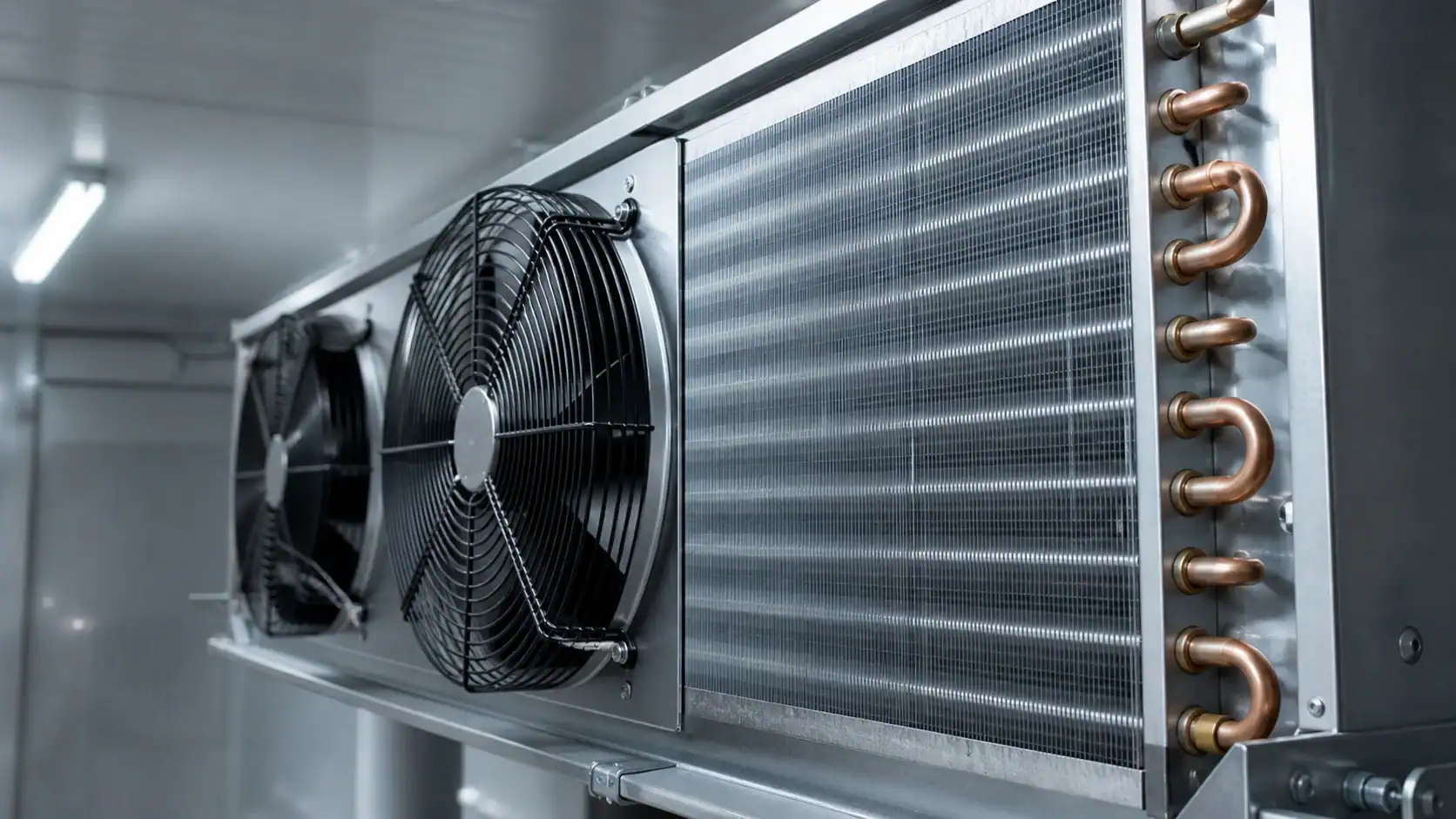
A unit cooler combines a finned evaporator coil, fan or fans, casing, drain pan, connections, and often a defrost arrangement. Refrigerant or secondary fluid absorbs heat in the coil while the fan circulates room air. The assembly may be ceiling mounted, wall mounted, low profile, cubic, slanted, or built for a large warehouse or process room.
The term is sometimes used loosely for a coil-only evaporator. That can create a scope problem. A coil supplier may quote the heat-transfer core while another supplier quotes a complete fan-equipped assembly. Ask every bidder to state whether the quotation includes the casing, fans, guards, motor controls, drain pan, defrost hardware, sensors, supports, wiring, and commissioning documents.
The AHRI 420 and 421 unit-cooler scope is a useful reference for defined forced-circulation free-delivery unit coolers. It does not remove the need to review the installed room, rack plan, humidity, frost, doors, and maintenance access.
How the assembly removes heat
Warm room air crosses the coil face. Heat moves through the fin and tube surface into the refrigerant or fluid. The fan then returns cooler air to the room. The result depends on coil surface temperature, refrigerant distribution, face velocity, fan curve, fin spacing, air bypass, room mixing, and the condition of the surface.
An apparently large coil can underperform if the fan cannot overcome pressure drop, the circuiting does not match the duty, or the discharge air returns directly to the inlet. A smaller assembly can perform well when the load, air path, and service conditions are defined together.
Choose the unit cooler configuration
Start with the space envelope and the air pattern, then compare cooler families. A low-profile unit may fit a shallow ceiling but have less coil depth. A cubic or slanted unit may provide more face area and throw for a medium room. A large industrial cooler may use several fans, a deeper coil, heavier supports, and a more demanding defrost and drain arrangement.
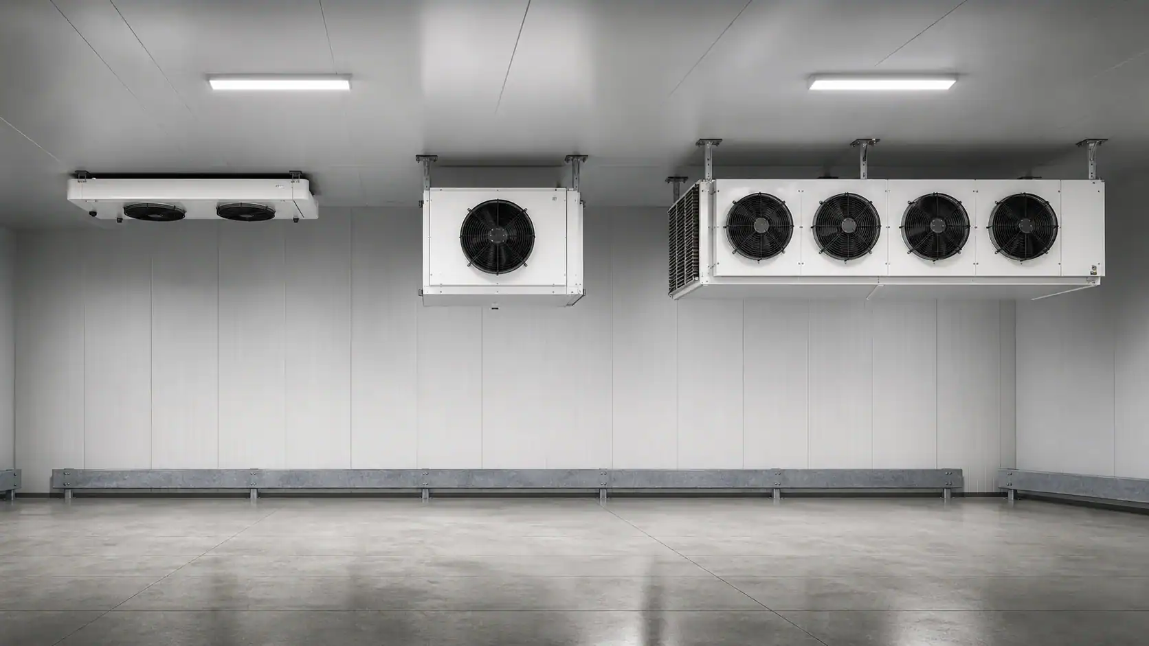
Do not select by the casing name alone. Record the actual face dimensions, depth, row count, fin pitch, fan diameter, airflow, sound, motor heat, connections, drain position, and service side. Confirm whether the published rating is clean-coil, dry-coil, wet-coil, or frosted, and whether the fan value is free air or at the assembled coil resistance.
Room and product information to collect first
The load case should reflect the operating room, not only the empty envelope. Include product entering temperature, pull-down or holding duty, infiltration, lighting, people, motors, wall and ceiling transmission, door events, defrost recovery, and the desired room temperature. For a process room, state the batch cycle and the time available for cooling.

| Input to collect | Why it changes unit cooler selection | Evidence to send | Open decision to close |
|---|---|---|---|
| Room temperature and range | Sets evaporating condition, frost risk, and product margin | Design setpoint, allowable swing, ambient range | Confirm whether the unit is for holding, pull-down, or both |
| Product and load | Determines heat removal, moisture release, and air sensitivity | Product mass, entering temperature, target temperature, package or pallet plan | Confirm peak batch and normal operating load |
| Room geometry | Controls air throw, return path, and short-circuit risk | Plan, section, rack height, beams, doors, and clearances | Mark the maximum storage line and unit locations |
| Infiltration and humidity | Changes latent load, frost, and defrost frequency | Door schedule, airlock details, humidity or dew point | Confirm the worst credible door and loading case |
| Operating schedule | Affects staging, fan control, defrost, and service windows | Shift pattern, pull-down time, defrost windows | Identify the condition used for acceptance testing |
Match coil duty, airflow, and air throw
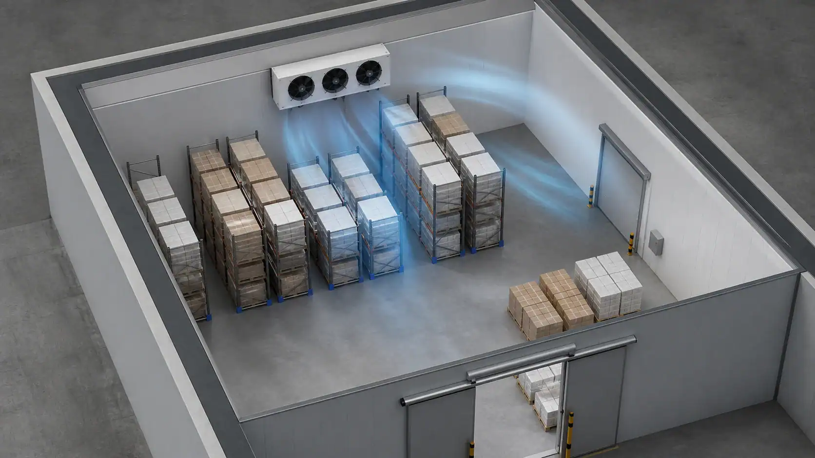
Capacity and airflow must be reviewed together. The coil removes heat, while the fans create a circulation loop. A room may show an acceptable average temperature while a remote aisle or product stack stays warm because the discharge jet stops early or the return path is blocked.
Draw both paths. Show the supply direction from the fan, the clear ceiling or aisle route, the return route to the coil, and the effect of racks, lights, beams, columns, doors, and high pallets. The existing industrial air cooler air-throw guide covers room coverage in more detail; this page uses the same principle as a unit-cooler selection gate.
Coil geometry and fin spacing
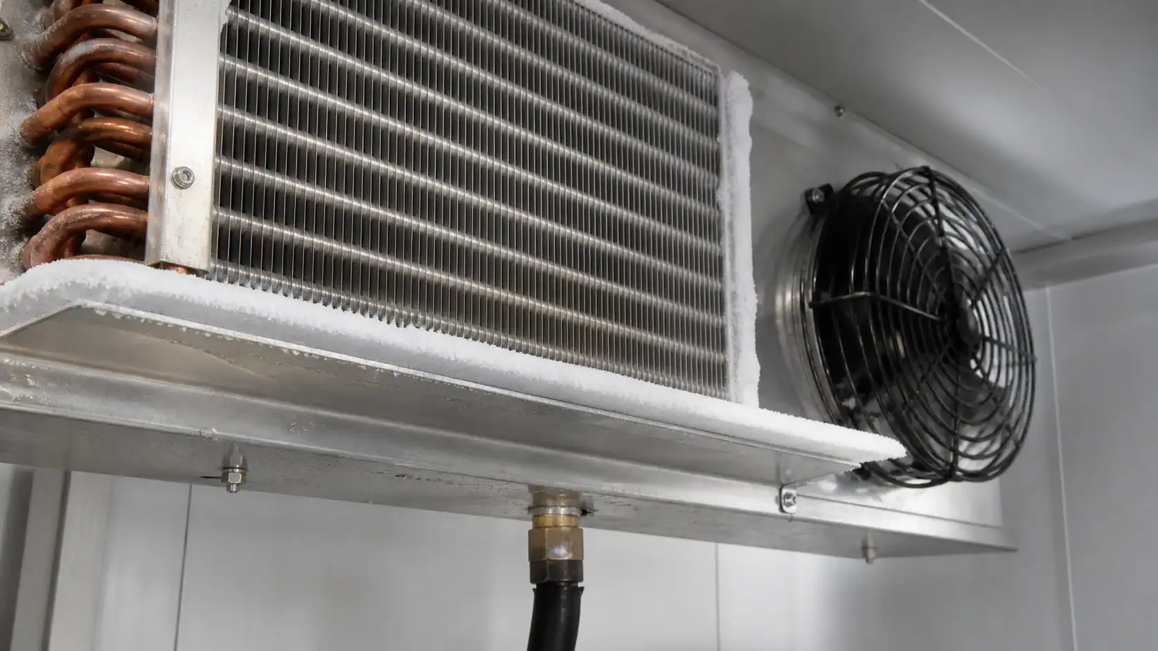
Tube diameter, circuiting, row count, face area, depth, fin material, fin thickness, and fin pitch all affect capacity and pressure drop. Wider fin spacing can help with frost and cleaning in low-temperature service. Tighter spacing may fit more surface into a small face but can block sooner and require more fan pressure. Ask the supplier to state the design basis instead of treating a fin pitch as a universal recommendation.
Fan curve and air-side resistance
Request airflow at the selected coil and the declared static pressure. Free-air fan volume is not the same as assembled-unit airflow. Guards, casing, filters, louvers, coil frost, duct transitions, and room restrictions can change the operating point. If variable speed is proposed, record the minimum speed that still maintains room coverage and avoids local drafts.
The term air throw also needs a definition. One supplier may report the distance to a terminal velocity, while another may show a catalogue projection under a different outlet or room condition. Compare the criterion, measurement origin, outlet pattern, fan state, and coil condition before using two throw numbers in a purchase decision.
Select defrost, drain, and frost protection
When a coil surface is below the dew point, condensate forms. At low temperature it freezes and reduces free area. Frost raises air-side resistance, lowers airflow, and can move the cold zone across the room. A unit cooler selection should therefore include the moisture load, fin spacing, defrost method, termination control, fan restart, pan, drain, and service access.
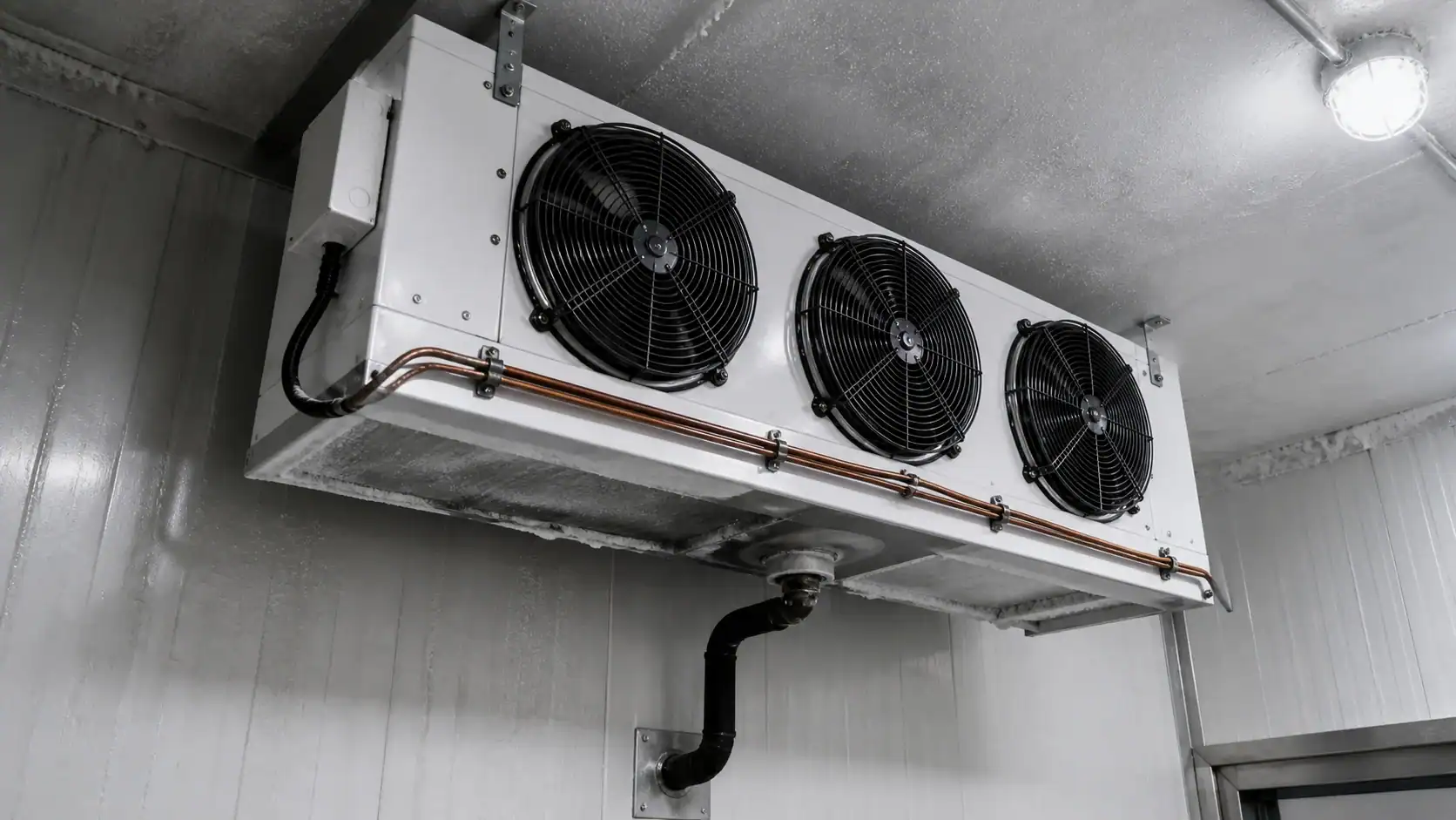
Electric defrost, hot-gas defrost, and off-cycle defrost can each be suitable in a defined application. The selection depends on room temperature, humidity, refrigerant architecture, available controls, product exposure, power, and the time allowed for recovery. Do not promise a universal defrost interval. Ask the supplier to state the assumptions and the evidence required at commissioning.
| Service condition | Coil and defrost question | Drain and control question | Buyer check |
|---|---|---|---|
| Medium-temperature cooler | Will condensate leave the fins without excessive carryover? | Is the pan slope and drain outlet accessible? | Confirm wet-coil rating, pan material, and cleaning path |
| Low-temperature freezer | How much frost can the passages accept before airflow falls? | Where are heaters, sensors, termination, and fan restart controls? | Confirm defrost energy, recovery time, and residual-ice inspection |
| High-humidity process room | Is the surface and coating compatible with repeated wetting? | Can the drain keep pace with condensate during peak load? | Provide dew point, sanitation method, and drain test |
| Frequent door traffic | Does infiltration shift the frost pattern or defrost demand? | Can the control sequence handle repeated load changes? | Include door events and the worst loading condition |
| Food or cleanable application | Can the casing, pan, and fins be reached without damage? | Are chemicals, rinse, drying, and access documented? | Approve the service method with the equipment owner |
The EPA Section 608 resources provide U.S. refrigerant-handling context. They do not replace the project-specific refrigerant, pressure, safety, and service requirements that belong in the equipment specification.
Confirm refrigerant, materials, and connections
State the refrigerant or secondary fluid, evaporating condition, design pressure, test pressure, connection sizes, connection orientation, circuiting, and allowable pressure drop. Natural-refrigerant systems such as ammonia or carbon dioxide require an application-specific materials and pressure review. Do not transfer an appliance-coil assumption to an industrial system without a qualified check.
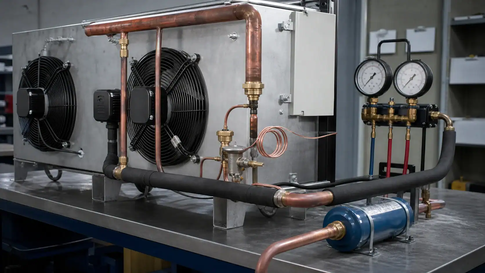
Review the coil, frame, fins, drain pan, fasteners, brackets, insulation, and coating as separate material decisions. Salt, cleaning chemistry, grease, humidity, and wet-dry cycles can affect different surfaces in different ways. If a coating is requested, specify the exposed area, surface preparation, masking, joining, inspection, and acceptance evidence. A generic corrosion-resistant phrase is not a measurable purchase requirement.
The ASHRAE standards and guidelines resource can help a project team identify the applicable design references. Final pressure ratings, relief protection, refrigerant suitability, and code compliance must be reviewed by the responsible engineer.
Plan mounting, service, and commissioning
Mounting height and discharge direction affect coverage. Provide support points, lifting method, vibration provisions, connection clearances, drain slope, access panels, fan removal path, and the maximum product height. Keep the service side reachable without moving unrelated equipment. A deeper cooler can fit the room envelope yet block a panel, sprinkler route, or maintenance platform.
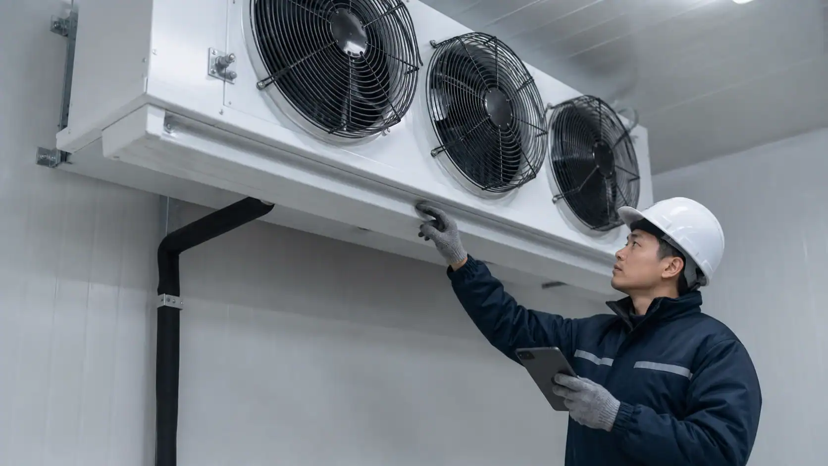
Commission the complete air-side assembly, not only the coil. Record room load, storage height, door state, fan stage, time since defrost, entering and leaving air, representative zone temperatures, and airflow direction. Repeat the check after a realistic loading condition. A single centerline velocity or one cold-surface reading cannot prove uniform room coverage.
| Configuration | Best-fit question | Main risk to check | Commissioning evidence |
|---|---|---|---|
| Low profile | Can the shallow assembly deliver the required duty and clearance? | Limited face or depth may increase pressure drop | Airflow at design fan speed, sound, and remote-zone temperature |
| Cubic or slanted | Does the discharge pattern suit the room and rack layout? | Short circuit or blocked return behind high storage | Supply and return path, face map, and door-event trend |
| Large industrial | Can the supports, piping, fans, and defrost handle the load? | Weight, vibration, service access, and multi-fan staging | Fan staging, frost recovery, drain flow, and structural check |
| Multiple smaller units | Does zoning improve coverage and redundancy? | Fan interaction or uneven control between units | One-unit-off case, zone temperatures, and return airflow |
Build an RFQ that suppliers can compare
An RFQ should define the result the sample must prove. Include the application, load, room, air path, refrigerant, coil, fan, defrost, materials, mechanical interfaces, testing, packaging, quantity, and schedule. Mark measured values, calculated values, preferred values, and open values separately.

RFQ fields for a complete unit cooler
| RFQ section | Minimum information | Supplier response to request |
|---|---|---|
| Application and load | Room temperature, product, load profile, infiltration, humidity, and duty type | Rating condition, assumptions, and capacity margin basis |
| Refrigerant side | Refrigerant, evaporating condition, design and test pressure, connections, and circuiting | Pressure drop, materials, connection drawing, and compatibility statement |
| Air side | Fan curve, airflow, static pressure, face velocity, outlet pattern, and air-throw criterion | Assembled-unit airflow, fan power, sound, and coverage assumptions |
| Coil and casing | Face, depth, rows, fin pitch, tube, frame, pan, coating, and supports | Released drawing, bill of materials, and revision control |
| Defrost and drain | Method, heater or hot-gas scope, termination, fan restart, pan, outlet, and slope | Sequence, recovery assumptions, drain test, and service instructions |
| Quality and commercial | Leak or pressure test, dimensional report, performance check, quantity, packaging, and lead time | Inspection records, sample plan, packaging, and clearly stated exclusions |
If the fan, casing, controls, or defrost are excluded, show that exclusion beside the price. If the proposed design changes the original fin pitch, row count, fan, connection, or drain, request a deviation note and a validation plan. This avoids approving a dimensionally similar part that changes the installed performance.
Validate testing, change control, and packaging
Quality checks may include material and thickness, fin pitch, tube-to-fin contact, circuiting, connection positions, dimensions, brackets, coating coverage, drain, leak or pressure test, and packaging. The required records depend on the project. A fit sample can prove envelope and connection alignment while leaving thermal and air-distribution questions open.
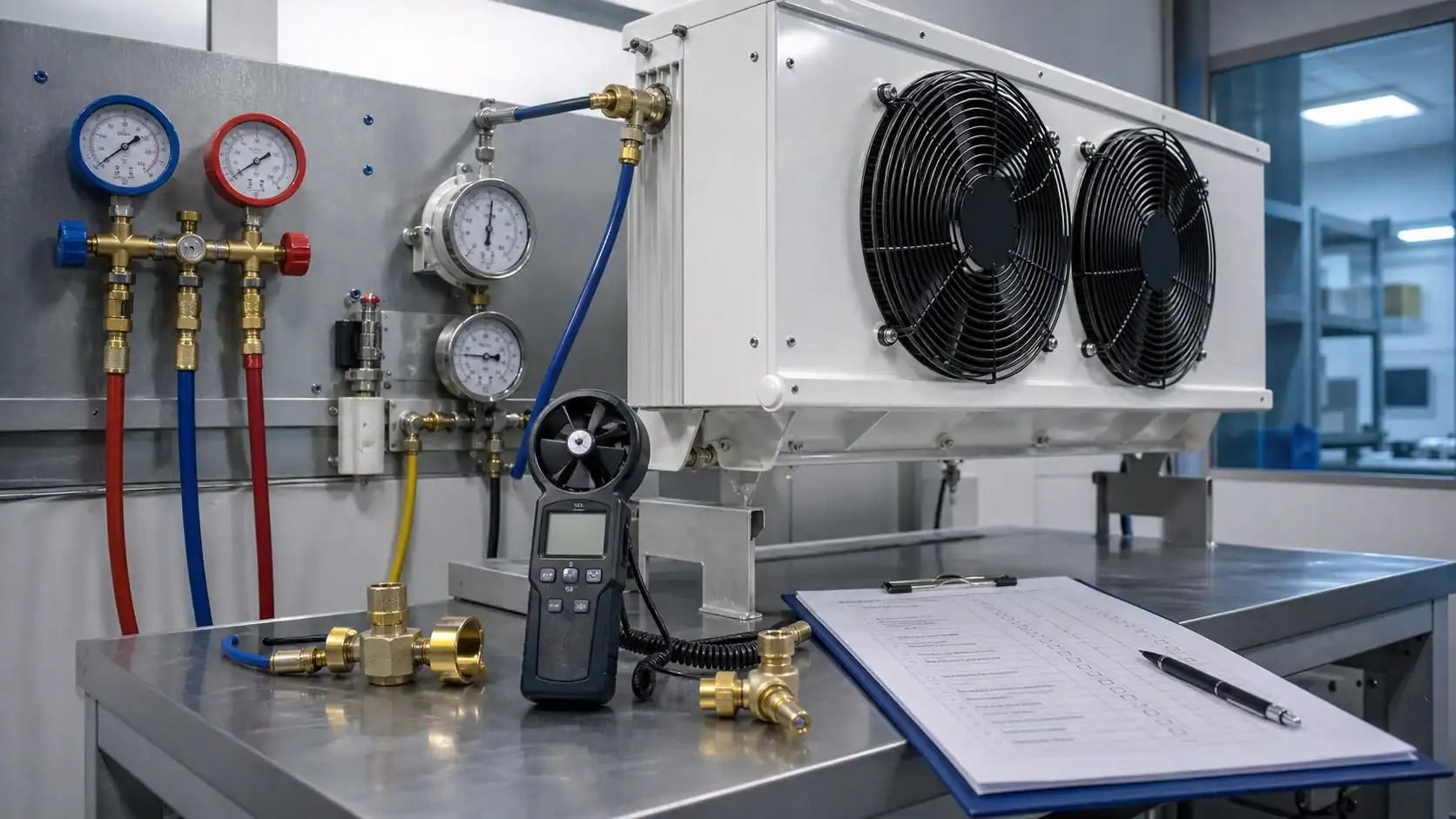
Use a controlled drawing revision for every change to fin pitch, material, circuiting, fan, casing, coating, drain, heater, sensor, bracket, or connection. Keep procurement, quality, service, and the equipment OEM on the same revision. When a problem appears, record the symptom, operating condition, proposed change, validation step, and approval owner rather than replacing random units.
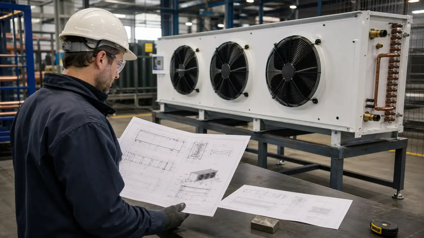
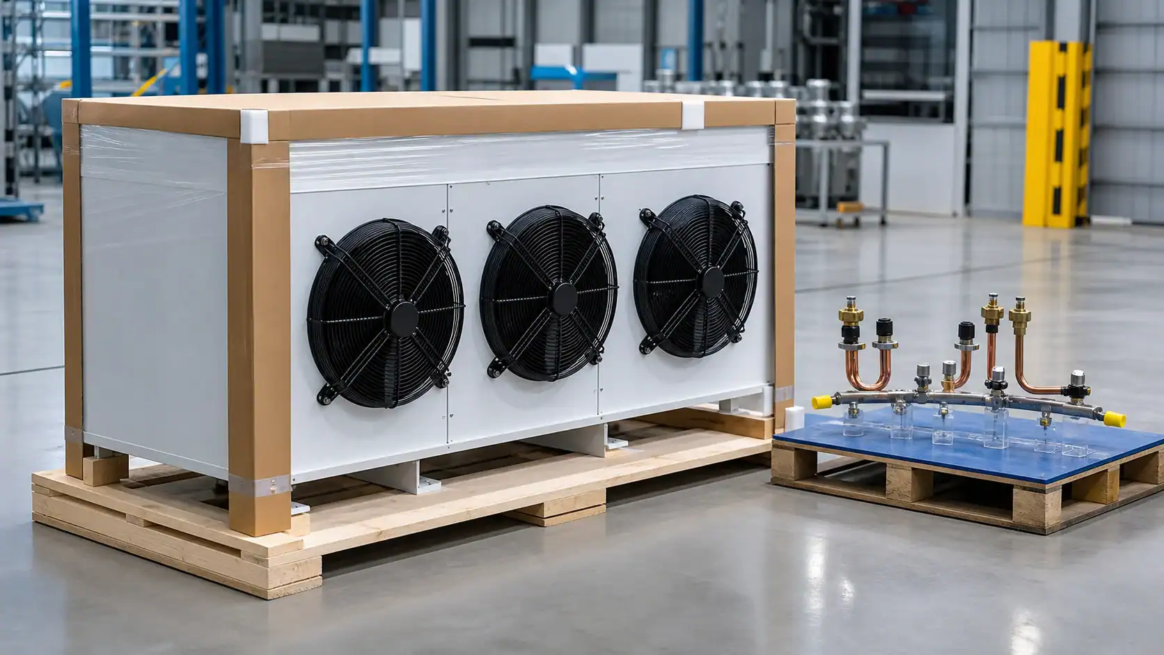
Protect the fin face, headers, connections, drain, fans, and brackets during transport. Use rigid face protection, support the assembly at approved points, cap connections, and define receiving inspection. At installation, remove shipping protection, verify airflow direction, confirm fan clearance, inspect fins, and record the drawing revision.
Send a unit cooler brief for review
For a quotation, send the room plan and section, equipment model or application, product and load data, temperature range, refrigerant, evaporating condition, airflow or fan information, fin and material preferences, defrost and drain details, dimensions, connections, quantity, packaging, destination, and the acceptance test you need. Clear photos of the existing unit can support an initial review, but they do not replace measured dimensions or operating data.
Use the Domi contact page to request a technical review. Domi can assess whether the requirement is best handled as a custom evaporator coil, a fan-equipped unit cooler, or a broader refrigeration assembly. Final capacity, pressure rating, materials, test records, lead time, and commercial terms remain project-specific.
Frequently asked questions
What does a unit cooler include?
A complete unit cooler commonly includes a finned evaporator coil, fan or fans, casing, drain pan, refrigerant connections, supports, and a defrost arrangement when the application requires it. Some quotations cover only the coil. Ask the supplier to list included and excluded items.
How do I size a unit cooler for a cold room?
Start with room transmission, infiltration, product load, lighting, people, motors, pull-down or holding duty, design temperature, humidity, and defrost recovery. Then match the coil, refrigerant condition, airflow, fan curve, and room air path. Capacity should be stated at a defined rating condition rather than copied from a generic catalogue line.
Does a larger unit cooler always cool a room better?
No. A larger coil may add capacity, but it can also add fan resistance, weight, cost, defrost demand, and service constraints. If the return path is blocked or the discharge short-circuits, more capacity will not correct the room distribution. Compare the complete assembly and layout.
Which defrost method is best for a unit cooler?
Electric, hot-gas, and off-cycle defrost can each be suitable. The choice depends on room temperature, humidity, refrigerant architecture, power, product exposure, controls, and recovery time. Ask for the defrost sequence, termination basis, drain behavior, and fan restart condition for the actual application.
What should an OEM include in a unit cooler RFQ?
Include the room and load, product, refrigerant, operating condition, capacity, airflow, fan and sound limits, coil geometry, fin pitch, materials, connections, defrost, drain, mounting, service clearance, testing, packaging, quantity, destination, and drawing revision. State which values are measured and which still need confirmation.
How can a buyer verify a unit cooler after installation?
Check airflow direction, fan operation, room-zone temperatures, drain flow, defrost recovery, frost pattern, noise, vibration, and the condition of the fin face. Test the representative loaded state and document time since defrost, door condition, fan stage, and storage height so the result can be repeated.