
Log mean temperature difference, or LMTD, describes the effective temperature driving force between two streams in a suitable heat exchanger model. Calculate it from the temperature differences between the streams at the two ends: LMTD = (ΔT₁ − ΔT₂) / ln(ΔT₁ / ΔT₂). Use the natural logarithm, pair temperatures according to the flow arrangement and check the model’s assumptions before using the result in a rating.
A correct formula with the wrong temperature pairs can produce a plausible answer and an incorrect area requirement. When reviewing a coil or heat exchanger proposal, connect the four terminal temperatures to the flow drawing, heat balance and stated rating method.
This guide develops one hypothetical liquid-to-liquid example, then separates the calculation from the checks needed for multipass equipment, refrigerant phase change and wet cooling coils. All numerical cases are illustrative, not Domi test results. The original illustrations explain concepts; they are not production drawings or evidence of a particular product’s performance.
What does log mean temperature difference measure?
The temperature gap between two streams generally changes as they exchange heat. LMTD accounts for that changing gap under the assumptions of the selected model. It is different from the temperature rise or fall of either stream on its own.

The basic logarithmic expression belongs to a steady heat-transfer model with suitable simplifying assumptions. The DOE Fundamentals Handbook, Volume 2, published in 1992, explains the terminal-difference calculation and notes the assumptions concerning specific heat and heat-transfer coefficients. It is a fundamentals reference, not a current product rating or certification document.
For a simple ideal arrangement with a suitable overall coefficient, the rating relationship is Q = U × A × LMTD. When a correction factor is required, a common form is Q = U × A × F × LMTD. Keep U, area and the correction method on a consistent basis. The heat transfer coefficient guide explains the separate meanings of h, U and UA.
LMTD has temperature-difference units. A difference of 10°C equals 10 K; a difference of 10°F equals about 5.56 K. Calculate both terminal differences in the same unit and keep the heat-transfer coefficient consistent with that unit. The logarithm’s ratio is dimensionless.
Record the four terminal temperatures
Write down hot-stream inlet and outlet temperatures, T_h,in and T_h,out, and cold-stream inlet and outlet temperatures, T_c,in and T_c,out. Identify each location on the flow drawing before subtracting anything.

The words “inlet” and “outlet” describe a stream’s direction. They do not necessarily identify the same physical end for both streams. In counterflow, the hot inlet shares an end with the cold outlet. In parallel flow, both inlets share an end.
Distinguish a fluid’s bulk terminal temperature from a tube-wall, fin-surface or room temperature. A wall temperature can be useful diagnostic evidence, but substituting it for the specified fluid temperature changes the calculation.
Also identify whether the four values are measured at one operating state, specified design targets or predictions. Combining a measured inlet from one test with a nominal outlet from another does not create a valid rating point. Keep the flow arrangement, fluid identities and pressure or phase information with the temperature record.
Pair the ends correctly for counterflow
In ideal counterflow, the two streams move in opposite directions. At one physical end, compare the hot inlet with the cold outlet. At the other, compare the hot outlet with the cold inlet.

Use these terminal differences:
- ΔT₁ = T_h,in − T_c,out
- ΔT₂ = T_h,out − T_c,in
For the hypothetical program 80→50°C on the hot side and 20→45°C on the cold side, the differences are 80 − 45 = 35 K and 50 − 20 = 30 K. Therefore, LMTD = (35 − 30) / ln(35 / 30) = 32.44 K, rounded.
Changing the names of ends 1 and 2 does not change the result: numerator and logarithm both reverse sign. Changing which temperatures occupy an end does change the result. Sketch the two arrows and terminal labels beside the calculation so another engineer can reproduce the pairing.
Use different pairs for parallel flow
In ideal parallel flow, both streams enter at the same end and travel in the same direction. Compare the two inlet temperatures at the inlet end and the two outlet temperatures at the outlet end.
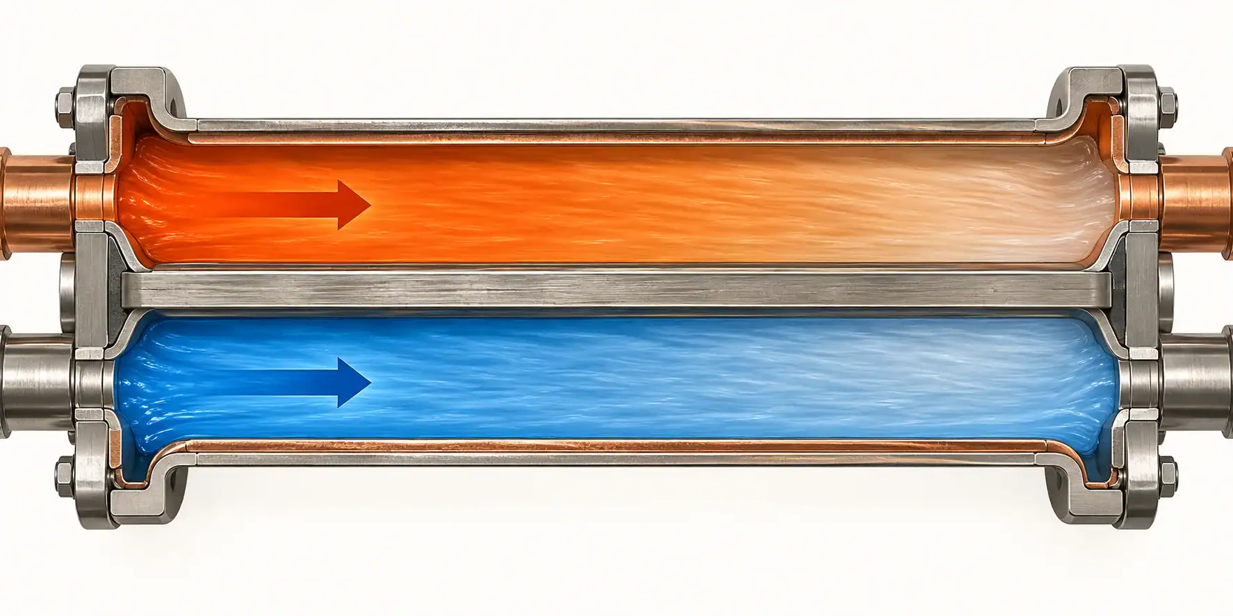
Use ΔT₁ = T_h,in − T_c,in and ΔT₂ = T_h,out − T_c,out. For the same hypothetical terminal targets, those gaps are 80 − 20 = 60 K and 50 − 45 = 5 K. This gives LMTD = (60 − 5) / ln(60 / 5) = 22.13 K.
Ideal arrangement
First end difference
Second end difference
Ideal arrangement: Counterflow
First end difference: Hot inlet minus cold outlet
Second end difference: Hot outlet minus cold inlet
Ideal arrangement: Parallel flow
First end difference: Hot inlet minus cold inlet
Second end difference: Hot outlet minus cold outlet
These are two designs asked to meet the same temperature targets. They do not show that reversing the connections on one fixed exchanger would preserve all four temperatures. With a fixed area, flow rates and inlet conditions, changing the arrangement generally changes the predicted outlets. The required conductance must be recalculated.
Work through a balanced 120 kW example
Check the heat balance as well as the temperature pairs. Assume steady operation, negligible heat loss to the surroundings and two single-phase liquids. Use a constant c_p of 4.0 kJ/(kg·K) for each. Let the hot flow be 1.0 kg/s and the cold flow 1.2 kg/s. Retain the four temperatures used above.
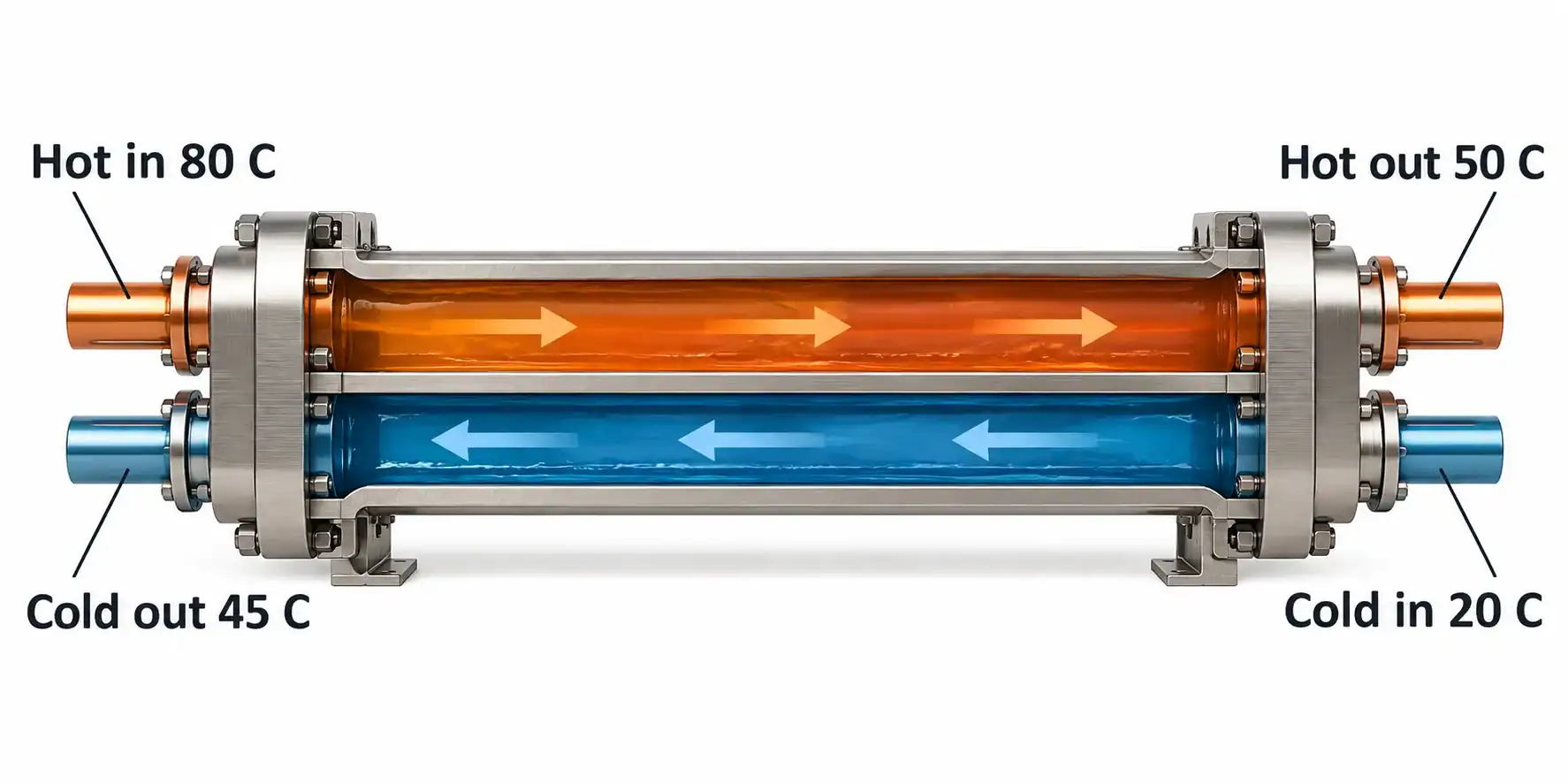
The hot side releases Q_h = 1.0 × 4.0 × (80 − 50) = 120 kW. The cold side receives Q_c = 1.2 × 4.0 × (45 − 20) = 120 kW. Both sides agree under the stated assumptions. For an actual fluid, use its appropriate properties rather than assuming this specific heat.
Alfa Laval’s plate heat exchanger calculation method identifies temperature programs, flow rates, heat load and allowable pressure losses among the design inputs. Its calculation framework supports keeping those quantities together. The numbers here are a separate illustrative example.
With F = 1 for each ideal arrangement, the required UA is Q / LMTD:
Calculation basis
LMTD
Required UA for 120 kW
Calculation basis: Ideal counterflow
LMTD: 32.44 K
Required UA for 120 kW: 3.700 kW/K
Calculation basis: Ideal parallel flow
LMTD: 22.13 K
Required UA for 120 kW: 5.422 kW/K
Calculation basis: Parallel-flow arithmetic approximation
LMTD: 32.50 K
Required UA for 120 kW: 3.692 kW/K, which understates this model’s requirement
The arithmetic average of the parallel-flow end differences is (60 + 5) / 2 = 32.50 K. Substituting it for 22.13 K understates required UA by about 31.9%. If U were held constant on the same area basis, the calculated area would have the same percentage understatement. This is a conditional mathematical comparison, not a measured saving or penalty for any product.
Spirax Sarco’s heat-transfer explanation distinguishes logarithmic and arithmetic mean differences and explains why the changing driving force matters. Whether an approximation is acceptable depends on the actual end differences and the calculation’s purpose. The large imbalance between 60 K and 5 K makes the shortcut unsuitable in this example.
Handle equal and nearly equal terminal differences
When both positive terminal differences are equal, the displayed formula gives 0/0 if evaluated literally. Its limit is the common difference. If ΔT₁ = ΔT₂ = 20 K, then LMTD = 20 K.

A spreadsheet should handle this limit rather than report an error or zero. When the gaps are very close, subtracting nearly equal numbers and dividing by a very small logarithm can also create numerical sensitivity. Use a validated logarithmic-mean routine or an appropriate stable implementation, and retain enough precision before rounding the final result.
An equal positive gap is different from an end gap approaching zero while the other stays positive. In the latter limiting case, LMTD approaches zero. A positive specified duty then demands increasing UA in the simple model. A zero or reversed end gap deserves a model and feasibility review; taking absolute values to force a positive spreadsheet result hides the issue.
Distinguish outlet crossover from a local temperature reversal
In counterflow, the cold outlet can be warmer than the hot outlet because those outlets are at different ends. That comparison alone does not establish a violation of the local heat-transfer direction.

For a separate hypothetical program, let hot liquid cool from 80 to 40°C while cold liquid warms from 20 to 50°C. The counterflow end differences are 80 − 50 = 30 K and 40 − 20 = 20 K. Both remain positive even though the cold outlet is 10 K warmer than the hot outlet. Compatible heat-capacity rates and sufficient exchanger conductance would still be needed to realize the program.
By contrast, a reversed local driving difference in the assumed simple heating model requires investigation. Recheck stream names, end pairing, measurement locations, flow direction and whether the assumed model represents the real arrangement. Four bulk terminal values cannot establish every local condition in complex multipass or maldistributed equipment.
Match the correction method to the actual geometry
Do not assign F = 1 to an exchanger just because the drawing contains opposing arrows somewhere. A shell-and-tube unit with several passes, or an air coil with crossflow and particular mixing behavior, can require a correction method or a more detailed rating model.

Where a correction-factor method applies, obtain F from the appropriate arrangement and temperature-ratio relationships. Ask the supplier to identify the reference counterflow LMTD, the correction method and the coefficient and area basis. F is not a discretionary multiplier for making an undersized proposal appear acceptable.
A manufacturer’s rating program may incorporate the geometry directly rather than expose a single F value. Request its model basis and returned operating data instead of inventing a factor. The shell-and-tube selection guide and plate heat exchanger guide cover the additional geometry and selection inputs for those equipment families.
Separate a condensing zone from the complete refrigerant circuit
An idealized condensation zone can have an approximately constant refrigerant temperature when a pure fluid changes phase at nearly constant pressure. That is compatible with an LMTD treatment for a suitable zone model; phase change does not automatically make every LMTD calculation invalid.
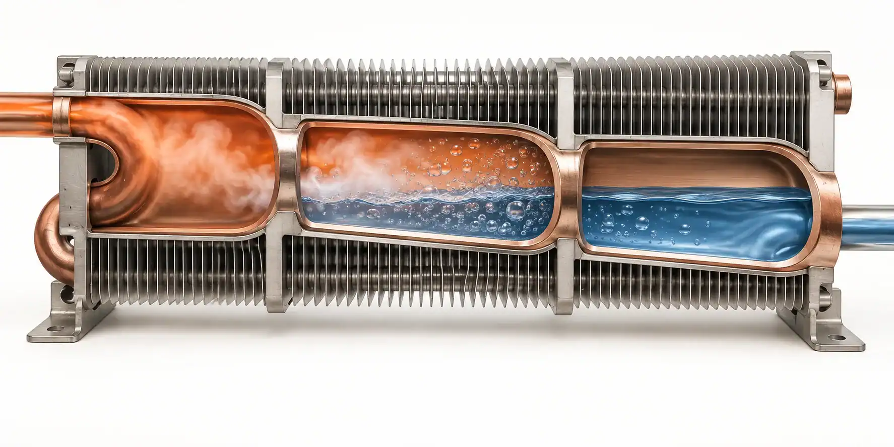
For a simplified isothermal zone at 45°C exchanging heat with air that warms from 25 to 35°C, the end gaps are 20 and 10 K. Their logarithmic mean is 14.43 K. This illustrates the temperature calculation only, not a complete air-coil rating.
An actual condenser can also include vapor desuperheating, liquid subcooling, refrigerant pressure loss and uneven air temperatures. Refrigerant mixtures may add temperature glide. Use a model that accounts for the relevant zones and properties rather than applying one saturation temperature to the whole assembly without justification.
Keep the zone calculation connected to the compressor and system operating point. The commercial refrigeration coil sizing guide describes the separate duty, airflow and configuration inputs that a coil proposal needs. A correct LMTD does not establish refrigerant charge, pressure capability or appliance approval.
Use an appropriate model when a cooling coil is wet
A dry-bulb temperature change alone does not describe the total air-side load when moisture condenses on a cooling coil. The air also loses latent energy. A liquid-to-liquid sensible-duty example cannot simply be reused as a wet-coil selection method.
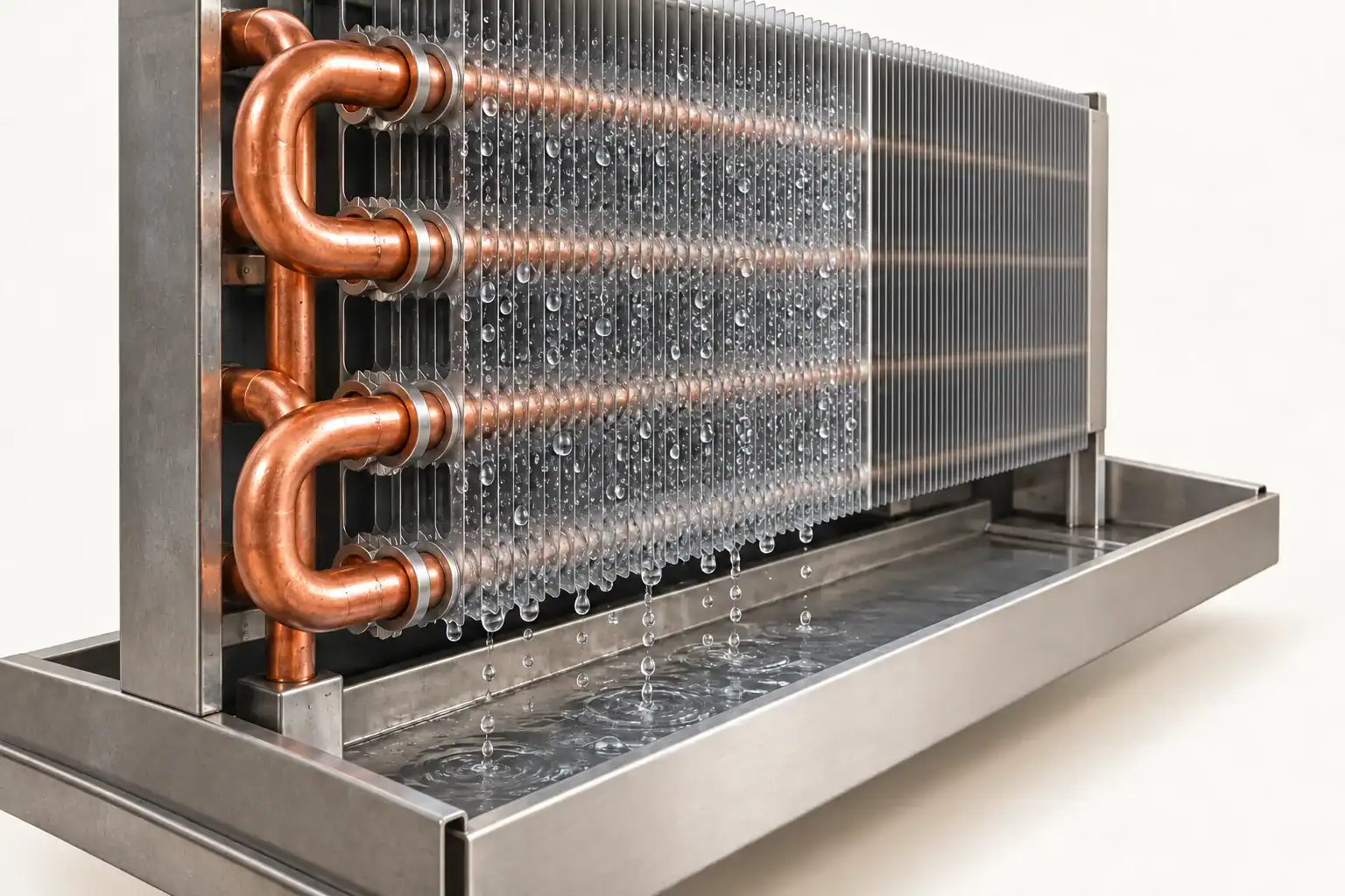
Supply the entering-air condition, humidity or an equivalent state definition, airflow, leaving requirements and fluid or refrigerant conditions. The coil rating method must account for the relevant wet-surface behavior and energy balance. A zone or enthalpy-based treatment may be appropriate; ask the supplier which method it uses and what assumptions remain.
Also identify whether the reported result describes a dry coil, a fully wet coil or a partly wet surface. Those are different rating conditions. The chilled water coil selection guide provides the related coil and air-state inputs. Do not treat a positive dry-bulb terminal gap as sufficient proof of total cooling capacity or dehumidification performance.
Check the measurements before rejecting the exchanger
Use temperatures and flow rates captured at the same stable operating point. Record sensor locations, calibration or uncertainty information, fluid composition and any heat exchange between the sensor and the exchanger connection.

Calculate the hot- and cold-side duties using suitable fluid properties, then compare them. If the calculated duties disagree beyond the agreed measurement and heat-loss allowance, investigate the data before inferring a new U value or rejecting the component. Fouling, bypass and control behavior can matter, but an inconsistent test record cannot identify which caused the discrepancy.
Small terminal gaps deserve particular attention. Suppose each temperature measurement has an illustrative error bound of ±0.5 K. A difference of two readings can then have a worst-case bound of ±1 K. Relative to a 5 K terminal gap, that is substantial. It is not automatically a ±20% uncertainty in LMTD; calculate sensitivity using both end differences and the actual measurement model.
Keep raw readings and the processing method with the test result. Avoid silently replacing a difficult measurement with a catalog value. A supplier should be able to reproduce the temperature pairing, heat balance and model used to accept the part.
Request a rating record that another engineer can reproduce
Start the inquiry with the required operating program. An LMTD value alone leaves the supplier without the temperatures and flow conditions behind it. Include the flow arrangement and the constraints the proposed equipment must satisfy.
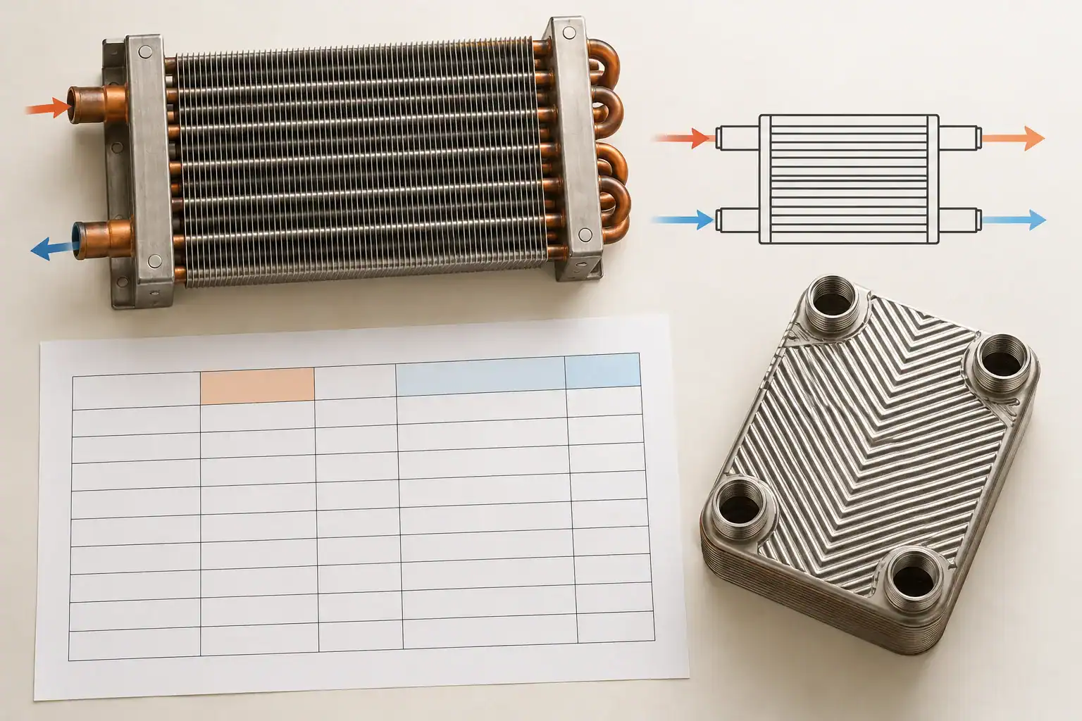
Send fluid identities and concentrations, four terminal temperature targets where known, flow rates, duty, operating pressures and allowable pressure losses. Add the equipment envelope, connection constraints, fouling or cleaning assumptions and the intended operating range. Identify unknown outlets instead of filling them with guessed values.
Ask for a returned drawing and rating sheet that identifies the flow pattern, calculation method, area basis, coefficient or conductance basis, pressure losses and any correction or zone treatment. Separate predicted values from measurements and record the geometry revision associated with each result.
If a proposal meets the duty only after changing the temperature program, treat it as an alternative operating case. Compare the consequences for the surrounding system before approving it. An exchanger that transfers the required heat at different inlet or outlet conditions has answered a different specification.
Frequently asked questions
What does log mean temperature difference tell you?
It describes the effective temperature driving force in the selected heat exchanger model. Combined with the appropriate conductance and any required correction, it supports a heat-transfer calculation. It does not by itself provide capacity, efficiency or a complete equipment selection.
What is the unit of log mean temperature difference?
Use a temperature-difference unit such as K, °C difference or °F difference. Celsius and kelvin differences have the same numerical value. Fahrenheit differences need conversion when used with a coefficient expressed per kelvin. Keep both input differences and the rating units consistent.
What happens when the two terminal differences are equal?
For equal positive differences, LMTD equals that common difference. Use the limiting value rather than evaluating 0/0 literally. A spreadsheet error in this case does not mean the exchanger has zero driving force.
Why not use the arithmetic mean temperature difference?
It can depart substantially from the logarithmic mean when the end gaps differ strongly. Check the error for the actual temperature program. In the worked parallel-flow case, substituting 32.50 K for 22.13 K materially understates the required conductance.
Is a higher LMTD always better?
No. At a stated duty and correction basis, a larger driving difference reduces the required UA. But a smaller LMTD can result from a deliberately close temperature approach or another process requirement. Judge the required temperature program, energy use, conductance and pressure losses together.
Can the cold outlet be hotter than the hot outlet?
In counterflow it can, because the outlets are at different physical ends. Check the actual end pairs and heat balance. This does not permit an arbitrary local reversal of the temperature driving force in an assumed simple model.
Can LMTD be used for condensers and evaporators?
It can be useful for appropriate phase-change zone models. Check pressure loss, temperature glide, superheat or subcooling regions and the air or secondary-fluid behavior. A complete refrigerant coil can require a more detailed rating than one overall terminal-temperature calculation.
Should I use LMTD or the effectiveness-NTU method?
LMTD is convenient when the relevant terminal temperatures are known or specified and the arrangement can be represented appropriately. When outlets are unknown, an effectiveness-NTU or detailed rating approach may be more convenient. The method still needs the correct geometry, properties and operating assumptions.
Turn the temperature program into a reviewable coil requirement
Keep the four temperatures, their locations and the flow arrangement together. Confirm the energy balance and model limits before using the calculated LMTD to infer UA or area. That record lets purchasing compare thermal proposals without treating a single formula result as proof of a complete design.
Domi’s custom coil fabrication service provides a destination for drawing and operating-requirement inquiries. Send the temperature program, fluid or refrigerant identity, duty, flow information and allowable pressure losses with the available envelope and connection drawing.
State whether the project concerns a dry liquid-to-air coil, a wet cooling coil or another proposed heat exchanger construction. Include the operating range and indicate which results are required from calculation, prototype testing or an existing approved reference. Domi can assess the supplied project information; the specific model, performance evidence, testing scope, quantity and lead time require confirmation.