
A serviceable beverage cooler coil needs a defined removal path, accessible fasteners and connections, supported tubing, and a replacement part that matches the approved cabinet interface. Prove those conditions on an assembled cabinet before release. A grille that exposes the condenser for cleaning does not, by itself, prove that the coil can be replaced without dismantling the cabinet.
An OEM after-sales team may discover an access problem only after the spare arrives. The coil matches the drawing, but a return bend catches the cabinet lip. A mounting screw faces a fixed side panel. The fan shroud can come off only after another assembly is removed. Purchasing has sourced the correct component; the service task still fails.
Engineering, purchasing and after-sales can review refrigeration serviceability against the same cabinet drawing and service trial. It covers mechanical access and approval planning, rather than instructions for opening a refrigerant circuit. Refrigerant work belongs to suitably trained service personnel following the appliance manufacturer’s procedure. The illustrations are conceptual design references, and their clearances require validation on the intended cabinet.
Separate cleaning, fan service and coil replacement
Start with the maintenance task, not with the phrase “easy access.” A brush reaching the fin face, a technician replacing a fan, and a technician removing the condenser need different working space. Give each task a separate access condition and acceptance point.
Task
Design question
Evidence to request
Task: Routine condenser cleaning
Design question: Can the approved cleaning tool reach the required surfaces?
Evidence to request: Demonstration with the grille, guard and surrounding equipment represented
Task: Fan or shroud service
Design question: Can the part be removed without damaging the coil or disturbing unrelated assemblies?
Evidence to request: Tool-access and removal demonstration using the intended spare
Task: Condenser replacement
Design question: Can the defined coil assembly leave the cabinet and its replacement be installed?
Evidence to request: Complete extraction, refit and verification trial with the approved service procedure
The current Beverage-Air VM refrigerator manual distinguishes user maintenance from service work on its hydrocarbon appliances. Its requirements apply to those models; another cabinet needs its own service instructions. Use manufacturer documentation to establish the task boundary before designing access around it.

For dust-screen access and cleaning geometry, use the separate beverage cooler condenser dust-control guide. Here, the acceptance point goes further: the failed component must leave the assembly by a documented route.
Draw the removal path as well as the installed envelope
An installed bounding box answers whether a condenser fits. A removal envelope answers whether it can travel past everything around it. Review the complete movement, including the first lift off a locating pin, the forward slide, any rotation, and the handover to a support surface.
Include return bends, headers, mounting tabs and protected connection ends in that moving envelope. The center of the fin pack may clear an opening while a tube bend strikes the cabinet. Also show where the technician’s hands and supporting equipment must go. A collision-free CAD animation is insufficient if nobody can safely hold the part at the end of the movement.
For a simple straight extraction, use a preliminary check:
Required travel = travel needed to clear the obstruction + handling allowance.
Suppose an uncharged mock-up must move 160 mm to clear a fixed front lip, and the project provisionally allocates another 40 mm for controlled handling. The trial needs 200 mm of supported travel. These are hypothetical design inputs, not recommended universal clearances. Cabinet width, component mass, tool use and the installation aisle may require a different arrangement. This travel calculation also excludes the technician’s separate working-space requirement.
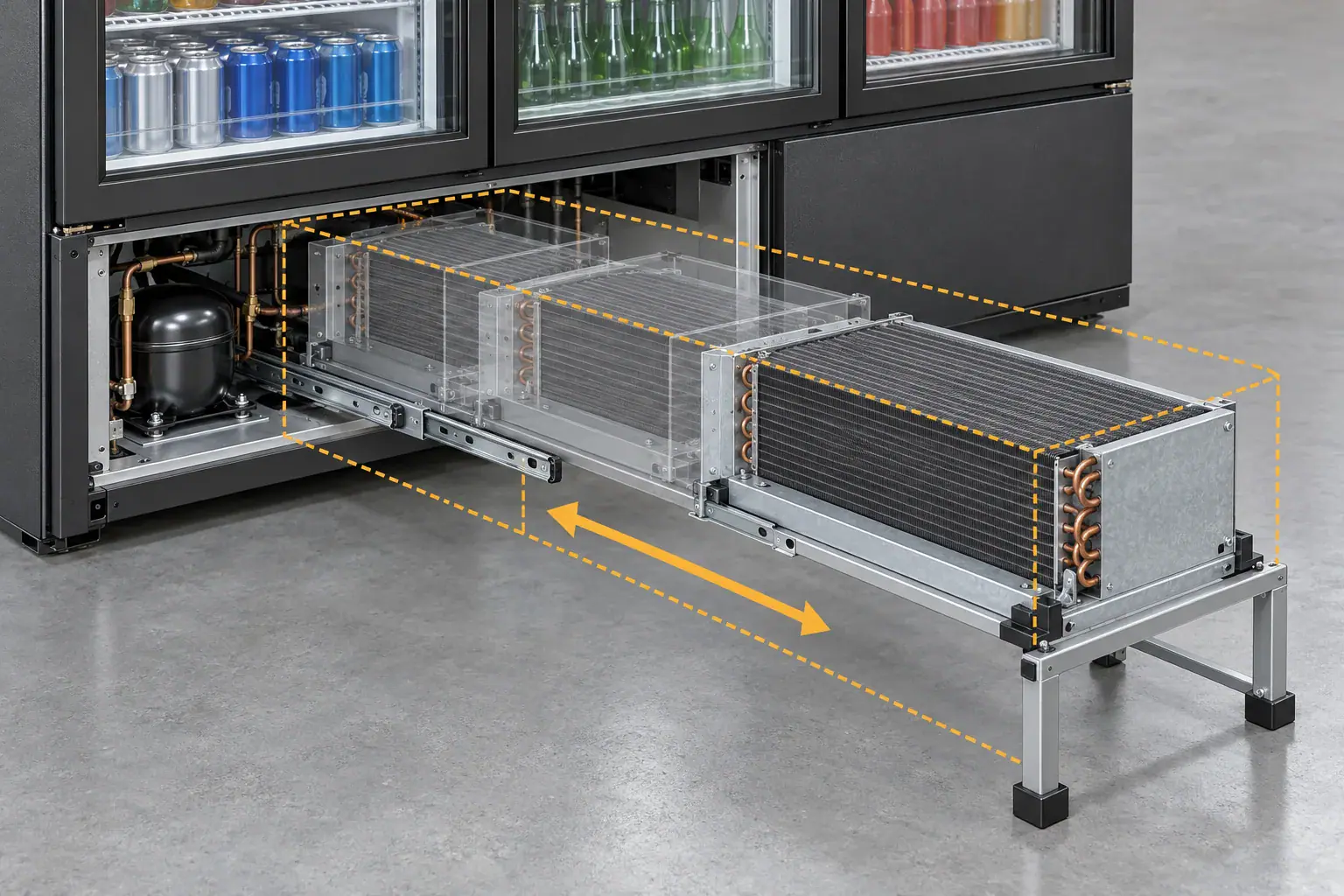
Show both the operating position and the service position on the cabinet drawing. Mark which panels may be removed and identify any fixed obstruction. If a store installation blocks the intended access side, the cabinet installation instructions must address that conflict before the product reaches the field.
Make the fastener reachable with the intended tool
Counting screws is a poor substitute for trying the tool. A small number of rear-facing screws can take longer to remove than several front-facing fasteners. Check driver alignment, engagement depth, hand clearance and the ability to retrieve the fastener without touching the fins.
Choose mounting features that support the component while the technician releases it. A slotted bracket can simplify positioning, but it needs a defined locating and retention function. A captive screw may reduce loose hardware inside the bay, provided the surrounding sheet metal leaves enough room to use it. These features still need vibration, retention and production review.
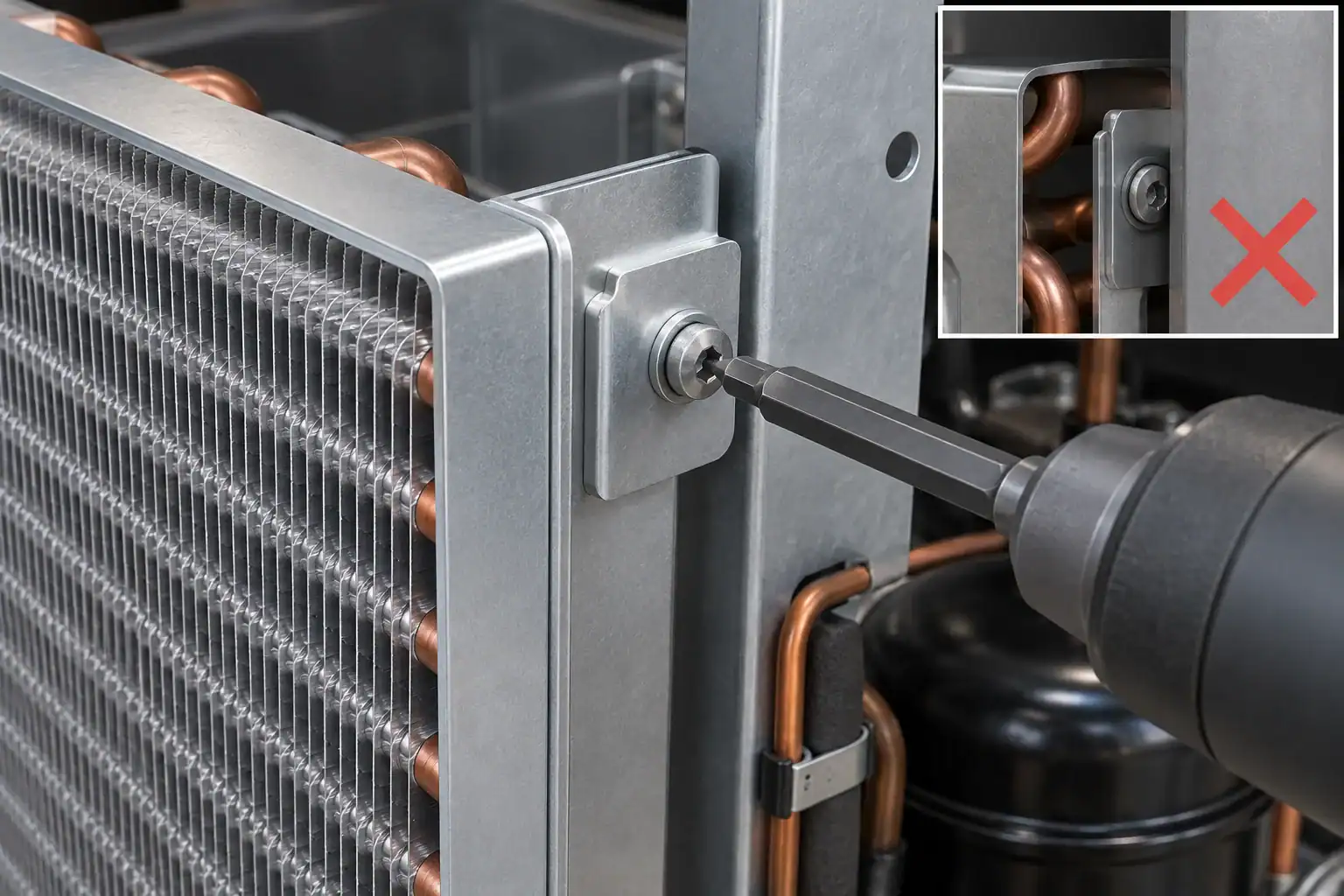
Run the access trial with the actual screw head, coating and bracket thickness. A hand-tightened prototype screw in an oversized hole does not represent the production joint. Record whether a standard field tool works or whether the service kit needs a special bit. If a special tool is unavoidable, identify it in the spare and service documentation.
Set a supported service position for tubing and harnesses
A pull-out tray is useful only within the movement its attached tubing and wiring can tolerate. Define that limit. Do not rely on a technician noticing that a line is becoming tight, and do not add an arbitrary copper loop without checking its thermal, vibration and safety implications.
Review formed bends, clamps, pass-through protection and moving-to-fixed transitions. At each intended position, check for rubbing, kinking, torsion, contact with hot surfaces and loading at a joint. Harness routing needs its own review so that electrical wiring cannot become the tray’s unintended travel stop.
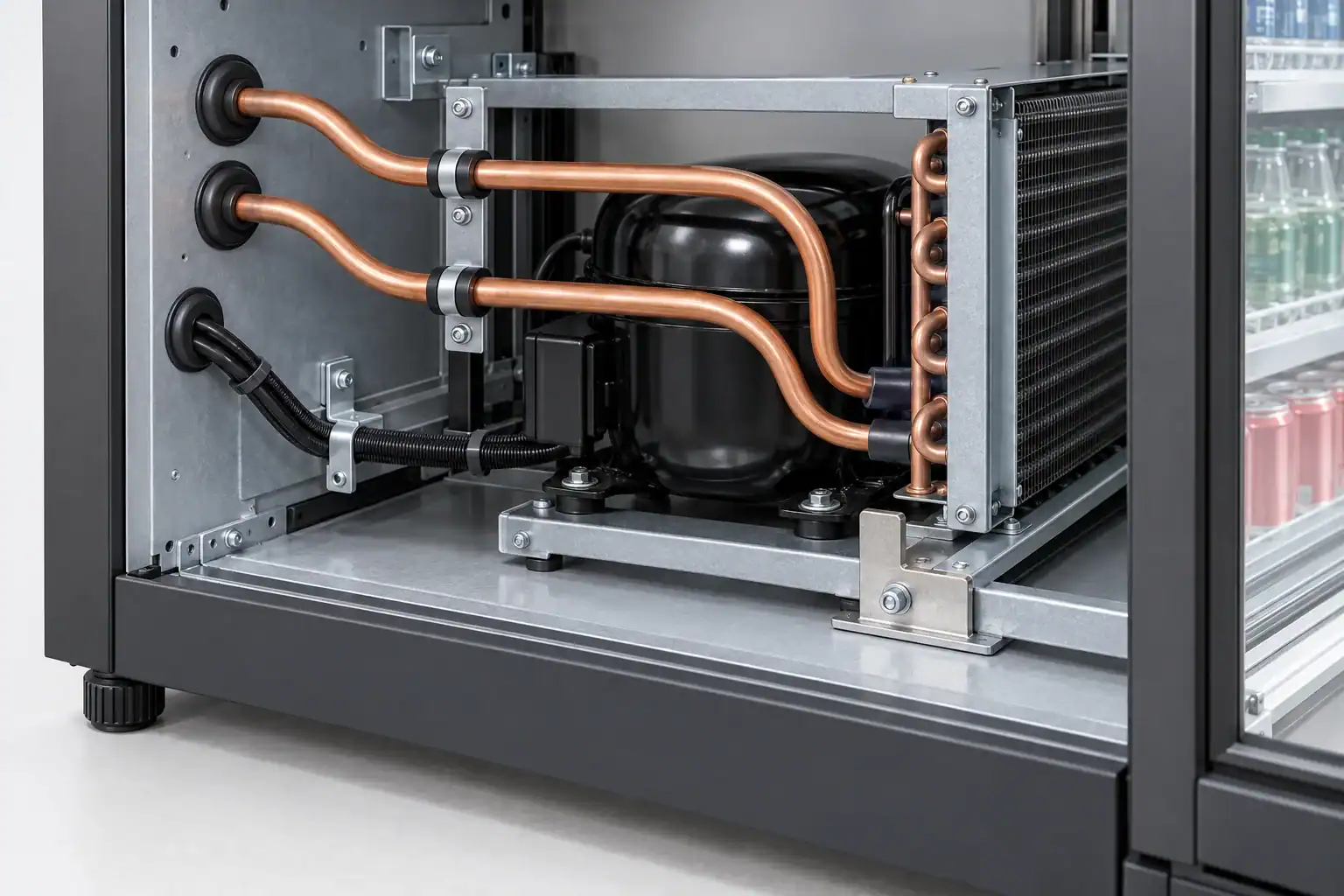
Separate an inspection position with the circuit intact from a replacement operation that follows an approved sealed-system service procedure. A design that permits limited inspection movement does not automatically permit full extraction while connected. Show the difference in the drawing and service instructions.
For hydrocarbon appliances, True’s R290/R600a service manual identifies model-specific replacement components, markings and service precautions. That supports an OEM design rule: preserve the approved appliance configuration and service requirements when improving access. This guide does not specify refrigerant recovery, charging, joining or leak-test procedures.
Make the air path easy to restore after service
Access is only half of the job. After the replacement, the cabinet must recover its intended airflow arrangement. A shroud that fits in two orientations, a gasket that is easily omitted, or a cover with ambiguous locating features can make a successful mechanical replacement a poor thermal repair.
Give shrouds and seals a clear location and inspectable seating condition. Consider whether the design can prevent a reversed installation through an asymmetric mounting pattern or another approved locating feature. Keep the part removable using normal service tools; adding permanent adhesive to compensate for a weak location can make the next repair harder.

Verify the reassembled unit at the relevant cabinet operating conditions. Compare the returned airflow path with the approved arrangement, including grille, seals and fan direction. A replacement should not create a bypass around the coil or feed hot discharge air back into its intake. The beverage cooler condenser selection guide explains the separate thermal and airflow inputs behind that acceptance check.
Decide whether the spare is a coil or a complete base
Compare the complete service cost when selecting the replacement assembly. A coil-only spare reduces the assembly supplied, but its field replacement may require more access, more interfaces and a longer appliance-specific procedure. A complete base can move some work into a prepared assembly, while increasing the spare’s weight, value and shipping volume.
Replacement scope
Potential advantage
Constraint to resolve
Replacement scope: Coil only
Potential advantage: Smaller component inventory and shipping package
Constraint to resolve: Field access, approved refrigerant work and complete interface verification
Replacement scope: Coil with frame, shroud or fan
Potential advantage: Some alignment work moves into the spare assembly
Constraint to resolve: Included components, electrical compatibility and part-number control
Replacement scope: Complete refrigeration base
Potential advantage: A defined assembly may simplify the cabinet-side exchange
Constraint to resolve: Mass, lifting support, cost, storage and all remaining cabinet interfaces

System architecture matters. Hillphoenix’s distributed-system serviceability discussion describes access and service choices for its equipment. It provides an example of treating service access as a system decision, not evidence that the same arrangement or result applies to a beverage cooler.
Choose the replacement boundary before freezing the spare drawing. Document exactly which sealed-system, mechanical and electrical interfaces remain to be handled in the field. Do not describe a base as a plug-in exchange unless the actual design and approved procedure support that description.
Put the service interfaces under revision control
A spare can look right and still fail at installation. Control the interfaces that the cabinet depends on: mounting datums, hole locations, connection direction, fan/shroud location, and the protected space around bends. Record which dimensions are critical to service access as well as normal assembly.
The service drawing should identify:
- The coil and cabinet revision pair being approved.
- Installed location, service travel and extraction direction.
- Mounting and support points, including removable brackets.
- Connection geometry and the required protected areas.
- Included shrouds, seals, hardware and any electrical components.
- Allowed alternatives and the review needed before substitution.
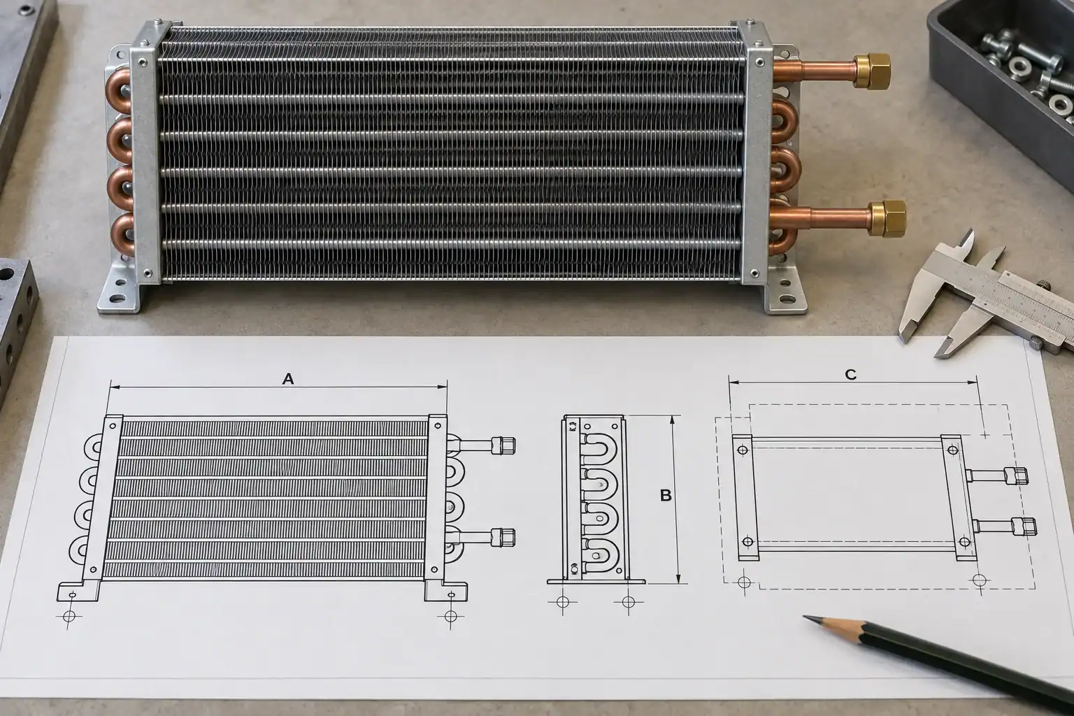
Keep capacity and construction requirements alongside those interfaces. Matching the outside dimensions does not establish thermal equivalence, refrigerant compatibility or appliance approval. A purchasing substitute needs engineering review even if the mounting holes line up. Use the existing coil drawing revision-control guide for the document handover, rather than keeping a separate informal spare drawing.
Specify a spare kit that matches the service task
Ask what must arrive with the coil for the technician to finish the approved job. Depending on the design, that may include a new gasket, a replaceable bracket, specified fasteners or a revised shroud. Put the agreed contents on the spare bill of materials instead of leaving them to a warehouse picker.
Identify the appliance model or approved compatibility range, part number, revision, orientation and handling instructions. An ambiguous label can send the wrong revision to a service appointment. Keep any claim of cross-model compatibility tied to a reviewed interface and performance record.
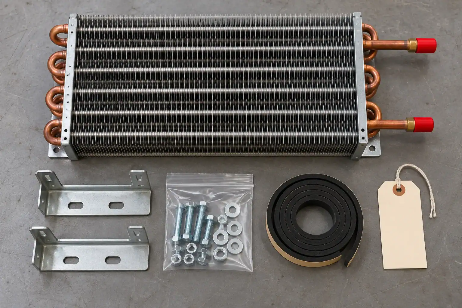
Separate packaging protection from installation parts. Shipping caps and temporary guards need clear removal instructions; supplied hardware needs a defined installation role. A kit should not encourage the technician to reuse a damaged seal simply because the replacement was omitted from the box.
Test access on a cabinet that represents the installation
A bare refrigeration base on a workbench is useful during development. It cannot establish the serviceability of the finished cabinet. Repeat the mechanical access trial after the cabinet contains its normal panels, feet or casters, wiring, drains, adjacent equipment and other features that affect the task.
Begin with a dry mechanical trial using a safe mock-up where appropriate. Then have the responsible service and engineering teams validate the complete approved procedure on the intended appliance. Keep refrigerant-related acceptance under that procedure; mechanical convenience does not replace it.

Observe the task from the technician’s position. Can the person see the connection or fastener? Is the removed panel supported? Does access require moving a stocked cabinet, and is that movement permitted by the installation instructions? Can the component be transferred to a support without resting it on a tube or fin edge?
Record the cabinet configuration, tools, operator, access restrictions and failed attempts. A service demonstration that needs an undocumented extra opening should trigger a design change or a revised service requirement. Repeat the affected trial after changing a bracket, connection or cabinet lip.
Measure labor by task before claiming a saving
A service-time comparison needs the same job boundary. Include access, removal, refit and the required verification. Keep travel, waiting for parts, product transfer and return-to-temperature time separate unless the study deliberately measures them. Otherwise, one team may report hands-on labor while another reports total downtime.
The following hypothetical planning comparison illustrates the method. The values are invented assumptions for calculation, not field measurements or a Domi service promise. Both designs retain the same 45-minute allowance for the approved service and verification work outside the mechanical access/refit changes.
Time segment
Baseline assumption
Revised-design assumption
Time segment: Obtain cabinet access
Baseline assumption: 25 minutes
Revised-design assumption: 12 minutes
Time segment: Release and remove the defined part
Baseline assumption: 15 minutes
Revised-design assumption: 15 minutes
Time segment: Position and mechanically refit the spare
Baseline assumption: 30 minutes
Revised-design assumption: 18 minutes
Time segment: Other approved service and verification work
Baseline assumption: 45 minutes
Revised-design assumption: 45 minutes
Time segment: Restore covers and record the job
Baseline assumption: 15 minutes
Revised-design assumption: 10 minutes
Time segment: Total
Baseline assumption: 130 minutes
Revised-design assumption: 100 minutes
The arithmetic difference is 30 minutes, or 0.5 labor-hour per job. At an assumed labor rate of $60 per hour and 200 qualifying jobs, the modeled labor difference is 0.5 × $60 × 200 = $6,000. It excludes parts, travel, repeat visits and downtime. A business case must replace these assumptions with measured task times and the actual service mix.
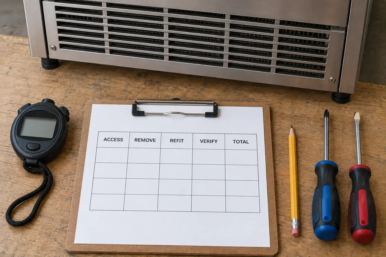
Use the breakdown to locate the design issue. If access consumes the time, changing the spare’s unit price does little to address it. If verification takes longer after a design change, include that increase. Never shorten a required safety or performance check to make the redesigned cabinet appear faster to repair.
Protect the spare until it reaches the cabinet
Serviceability extends to the replacement arriving in usable condition. Ask the packaging design to support robust frame locations and protect fins, bends and connection ends. A damaged mounting tab can change the fit; a deformed fin pack can undermine the intended airflow.
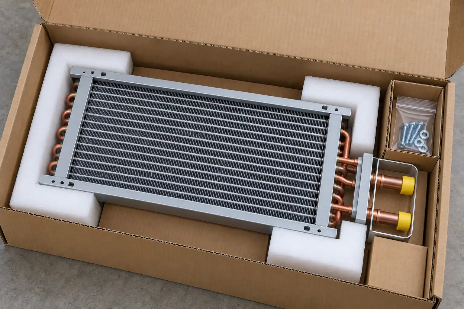
Review how a technician unpacks the part with ordinary available space. Small hardware should remain identifiable, and the label should remain readable after shipping. Photograph the agreed packing configuration and record which features protect which vulnerable surfaces. Choose handling and transport validation for the actual distribution route; a neat box photograph is not a transit-test result.
Give the receiving team a short inspection boundary. If a connection guard is displaced or a frame is bent, the part needs assessment before installation. Avoid asking a field technician to straighten an unknown defect merely to keep a service appointment on schedule.
Release a serviceable design with a reviewable RFQ
Send the supplier both the thermal requirement and the service interface. The coil manufacturer can review a component drawing, but the cabinet OEM must supply the surrounding constraints that determine its removal route. Include photographs or CAD views of the cabinet bay, the required extraction direction, obstructions and the intended replacement boundary.
Request a returned review that separates confirmed dimensions from proposed changes and unresolved assumptions. Useful inputs include the refrigerant and operating conditions, heat-rejection duty, airflow, material requirements, drawing revision, mounting datums, connection positions, sample quantity and the planned service trial. If the service procedure is still being developed, say which decisions remain open.

Before the pilot order, assign responsibility for the coil inspection, cabinet access trial, spare compatibility check and final appliance verification. Keep the results linked to one revision pair. The acceptance record should show what was demonstrated, who approved it, and what a later change would require the team to repeat.
Frequently asked questions
What makes a beverage cooler condenser coil serviceable?
A defined removal path, reachable fasteners and service interfaces, suitable component support, and a spare that matches the approved cabinet configuration. Validate the entire task on the assembled cabinet, including the checks required after refitting.
Is a removable front grille enough for condenser replacement?
Usually it proves only that an opening exists. The coil still needs clearance for bends, brackets, tools and handling throughout extraction. Demonstrate full removal and refit using the intended procedure before treating the grille as replacement access.
Can a pull-out tray move while its copper tubing remains connected?
Only within a movement specifically reviewed and approved for that appliance. Tubing, joints, clamps and harnesses must accommodate the stated position. An inspection position is not permission for unrestricted travel or complete extraction.
Should the OEM stock a coil or a complete refrigeration base?
Compare the approved field work, weight, spare cost, shipping, inventory and remaining interfaces. A complete base may simplify one cabinet’s exchange while being unsuitable for another. Select the replacement scope from the demonstrated service task.
Does the replacement need the same outside dimensions?
It needs the approved interface and operating requirements. Outside dimensions alone do not establish connection fit, mounting compatibility, thermal duty, airflow or refrigerant suitability. Review and document any proposed change before approving the spare.
How can an OEM measure a serviceability improvement?
Time the same defined task on representative cabinet configurations. Separate access, removal, refit and verification, and report the tools and restrictions. Compare complete results rather than counting screws or publishing an unmeasured time-saving percentage.
Can access changes affect R-290 cabinet approval?
They can change features relevant to the approved appliance design, such as tubing routing, wiring, components, guards or labels. The responsible engineering and compliance teams should assess the actual change against the applicable product requirements and manufacturer procedure.
What should a replacement condenser coil RFQ include?
Send the cabinet model and drawing revision, coil data, refrigerant and duty, mounting and connection geometry, extraction envelope, replacement scope, quantity and validation requirements. Include the service restrictions that a component-only drawing cannot show.
Approve the removal route before freezing the cabinet
A serviceability drawing should show where the condenser operates and how the approved spare gets there. Check the complete trajectory, restore the air path, and retain the verification required by the appliance procedure. Record those checks as cabinet release requirements so later revisions receive the same review.
Review the cabinet envelope with Domi
Domi’s custom coil fabrication service provides a route for reviewing a drawing, sample or parameter sheet. Its OEM refrigerator and freezer solutions page describes the relevant appliance-component scope. For this discussion, send the condenser drawing together with the surrounding cabinet bay, mounting datums, protected connection areas and intended removal direction.
State whether the requirement is a coil-only spare, an assembly with shroud or fan, or a proposed cabinet design change. Add the operating conditions, airflow, refrigerant, sample quantity and the acceptance trial you plan to run. Ask Domi to identify feasible component options and any interface assumptions that need confirmation. The final cabinet service procedure and appliance approval remain part of the OEM’s project validation.