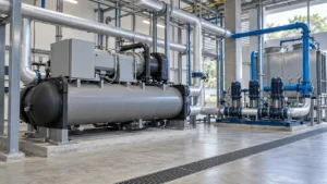
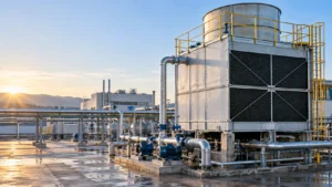
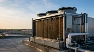
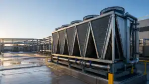
An evaporative condenser rejects refrigeration heat by combining a refrigerant coil, recirculated spray water, and moving air. The spray water wets the outside of the coil, a portion evaporates, and that phase change lowers the condensing temperature compared with a dry air-cooled condenser in the same weather. For an OEM buyer, the correct selection depends on refrigerant duty, entering wet-bulb temperature, water chemistry, coil material, airflow, service access, and the evidence required at approval. This guide explains the heat rejection path, the water balance, the main configurations, and the information a coil supplier needs before production.
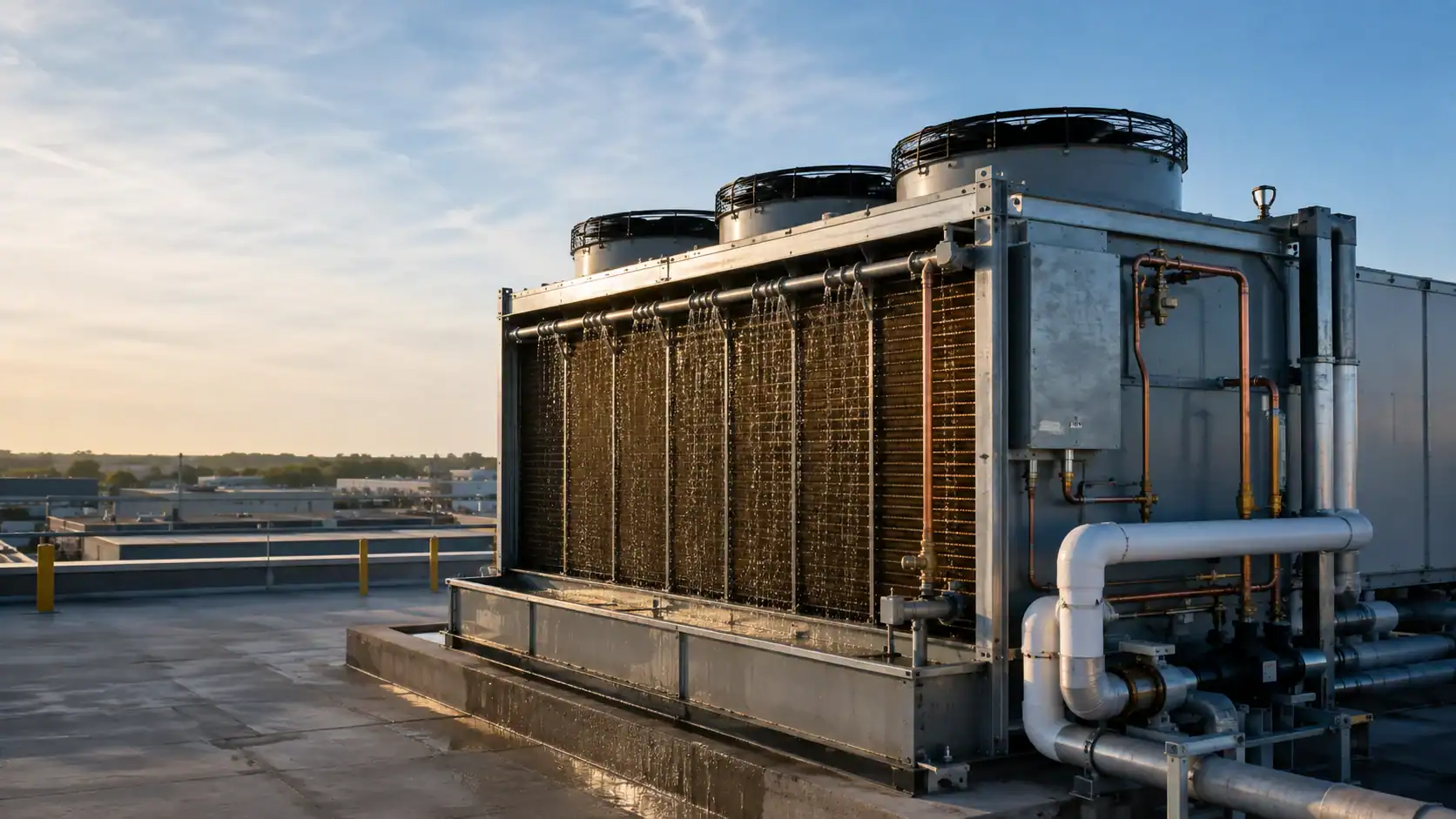
What is an evaporative condenser?
An evaporative condenser is a heat-rejection device in which hot refrigerant vapor flows inside a coil while water is sprayed over the coil surface and air passes across or through the wetted assembly. Heat leaves the refrigerant, moves through the tube wall, and is carried away by a combination of sensible air heating and water evaporation. The refrigerant changes from vapor to liquid inside the pressure-rated coil. The water circuit is separate from the refrigerant circuit, even though both are part of the same heat-rejection package.
The ASHRAE Terminology definition of evaporative condenser is a useful starting point because it identifies evaporation as the mechanism that improves heat transfer. The ASHRAE Handbook chapter on evaporative condensers adds the engineering context: performance is tied to entering air wet-bulb temperature, water distribution, coil construction, airflow, water treatment, and the approach between condensing temperature and wet bulb. Those inputs belong in a selection record, not only in a product brochure.
An evaporative condenser is not the same as a cooling tower. In a cooling-tower system, an open water loop rejects heat to air and a separate water-cooled condenser transfers refrigerant heat into that loop. In an evaporative condenser, the refrigerant coil is inside the evaporative assembly, so the refrigerant-to-air heat rejection boundary and the water spray section are in one package. That difference affects pressure class, inspection, piping, water treatment, and who owns the performance guarantee.
How the heat rejection path works
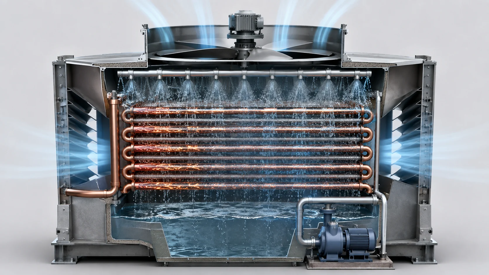
The working sequence is easier to understand when the refrigerant path and water path are followed separately:
- Superheated refrigerant vapor enters the pressure-rated condenser coil from the compressor discharge line.
- Spray pumps lift basin water to headers or nozzles above the coil. The water forms a film over the tube surface.
- Fans move outdoor air through the wetted coil and drift eliminator. A small portion of the water evaporates into the airstream.
- The refrigerant releases desuperheating heat, condensing heat, and any additional subcooling heat through the tube wall.
- Liquid refrigerant leaves the coil toward the receiver or liquid line, while unevaporated water returns to the basin.
- Makeup water replaces evaporation, drift, and blowdown. A conductivity or water-quality control may open the blowdown valve when dissolved solids rise.
The heat rejected is not just the evaporator load. A first system-level check is:
Q_reject = Q_evap + compressor heat input
For a compressor package, the supplier needs the design refrigerant mass flow, suction condition, discharge or condensing condition, and compressor heat input or compressor map. A coil that is sized only from the evaporator capacity can be undersized because the condenser must also reject compressor work. For a component replacement, the original duty sheet and nameplate data are more reliable than a frame dimension alone.
The U.S. Department of Energy evaporative-condenser guide is useful for explaining why lower condensing temperature can reduce compressor lift, while also noting that pumps, fans, water treatment, and maintenance remain part of the operating balance. Actual savings should be calculated from the selected compressor, climate, control sequence, and water cost rather than copied as a universal percentage.
Coil, spray, airflow, and basin components
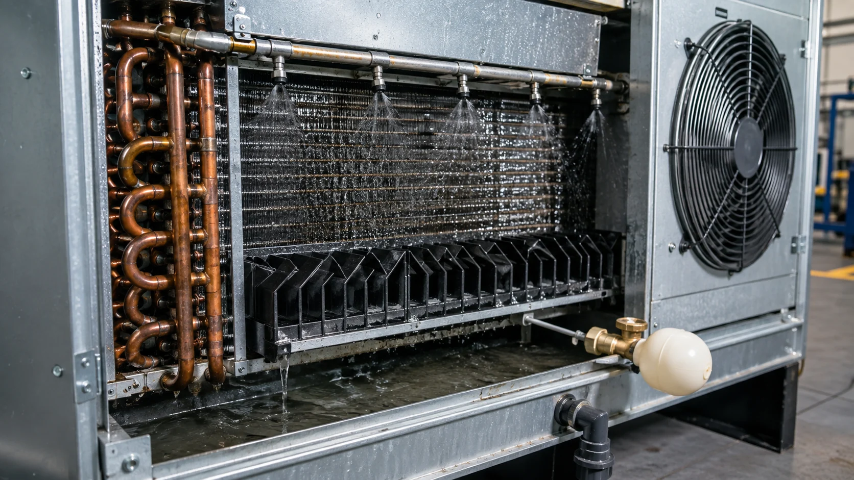
The coil is the pressure boundary and the main thermal surface. Tube material, tube diameter, wall thickness, coil circuiting, header design, return bends, support spacing, and connection orientation affect capacity, pressure drop, cleanability, and service life. Bare tubes are common where water wetting is required. Fin packs used for dry heat exchange should not be assumed to perform correctly when permanently wetted because fouling, drainage, and water distribution change the heat-transfer surface.
The spray system needs enough flow and coverage to keep the coil wet under the selected operating range. Nozzle type, orifice size, header balance, filtration, pump head, and access for cleaning should be recorded. A spray pattern that looks adequate at full flow can leave dry bands at turndown. A blocked strainer or a partially plugged nozzle can create a local hot spot even when the pump motor is still running.
Airflow completes the evaporative process. Axial fans are common for large heat-rejection packages, while smaller assemblies may use centrifugal fans. The selection should state air volume, fan static pressure, motor power, speed range, sound basis, and the expected effect of fouled drift eliminators or coil surfaces. Discharge recirculation caused by walls, screens, parapets, or nearby equipment can raise the entering-air wet bulb and reduce capacity.
The basin, float or level valve, pump suction, strainer, drain, overflow, and blowdown connection define the water-management boundary. Drift eliminators limit liquid carryover into the discharge air, but they do not remove the need for water treatment. Access panels and removable strainers are practical buying requirements because an inaccessible component becomes a recurring service cost.
| Component | Selection evidence to request | Service question | Common risk if omitted |
|---|---|---|---|
| Refrigerant coil | Refrigerant, design pressure, duty, tube and header material, circuiting, leak-test method, and drawing revision | Can the coil be isolated, drained, and pressure-tested without removing the package? | A dimensionally correct coil may fail the pressure or duty requirement |
| Spray headers and nozzles | Water flow, pump head, nozzle pattern, filtration, coverage at turndown, and replacement access | Can an operator remove a strainer or nozzle while the basin is isolated? | Dry coil bands, scaling, and uneven condensing temperature |
| Fans and airflow path | Air volume, static pressure, speed range, motor data, sound basis, and discharge clearances | What happens to capacity after one fan or a drift eliminator section is unavailable? | Warm-air recirculation or an overstressed remaining fan |
| Basin and water controls | Working volume, makeup, blowdown, overflow, conductivity setpoint, drain, and freeze protection | Is the basin easy to clean and fully drain for service? | High dissolved solids, biological growth, or freeze damage |
| Drift eliminator and access | Carryover limit, material, pressure drop, inspection method, and access panels | Can the eliminator be lifted out without damaging the coil? | Water carryover, blocked airflow, and difficult inspection |
Evaporative condenser vs air-cooled condenser vs cooling tower
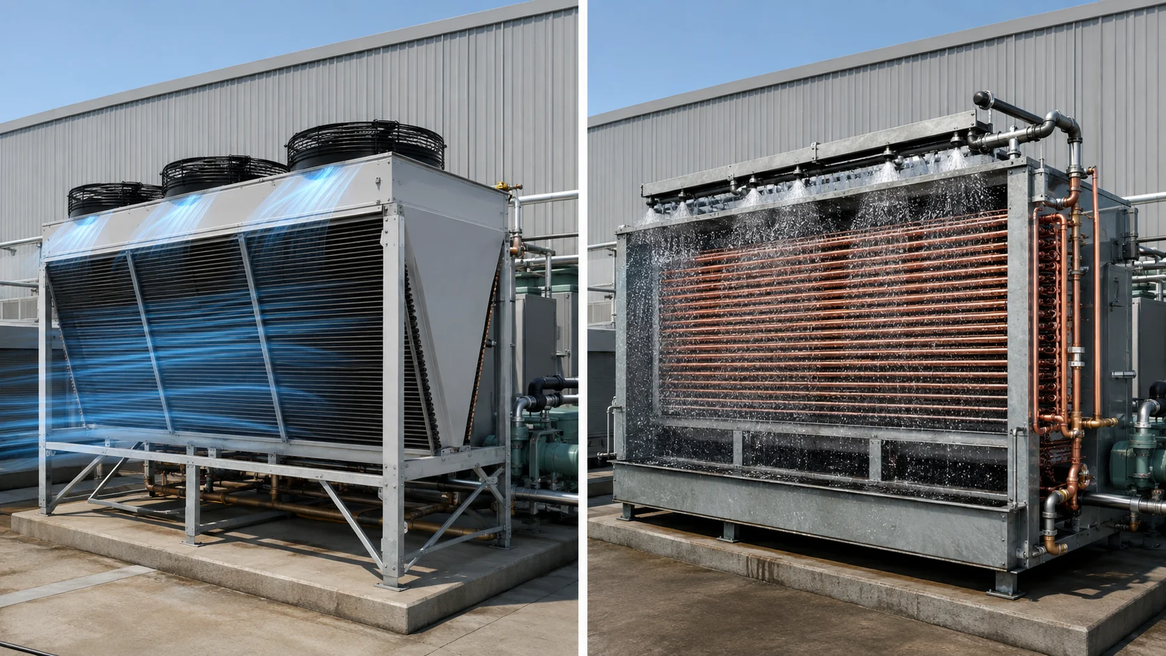
These technologies answer different project questions. An evaporative condenser is often selected when the buyer wants a lower condensing temperature than a dry air-cooled design can provide at the same footprint, and when the site can manage a controlled water supply. A dry air-cooled condenser avoids routine spray water but is more directly limited by outdoor dry-bulb temperature. A cooling tower can serve a large water loop, but it adds a separate water-cooled condenser, pumps, heat exchangers, and open-loop water responsibilities.
| Decision factor | Evaporative condenser | Air-cooled condenser | Cooling tower plus water-cooled condenser |
|---|---|---|---|
| Heat-transfer boundary | Refrigerant coil is wetted and exposed to airflow | Refrigerant coil is dry and exposed to airflow | Refrigerant coil transfers heat to a separate circulating water loop |
| Weather reference | Entering air wet bulb, dry bulb, humidity, and recirculation | Entering air dry bulb, altitude, and recirculation | Entering water temperature, wet bulb, tower approach, and water-loop flow |
| Water duty | Evaporation, drift, and blowdown require makeup and treatment | No water in the dry operating mode | Open or semi-open loop requires makeup, blowdown, treatment, and basin service |
| Typical footprint trade-off | Can support a lower approach with a compact coil, subject to water and airflow limits | Simple boundary but more coil face or fan power may be needed at high ambient | Centralized heat rejection can serve multiple loads but needs pumps and a separate condenser |
| Buyer should verify | Refrigerant pressure, spray coverage, water chemistry, drift, fan data, and controls | Coil duty, fan curves, ambient, fin cleaning, noise, and freeze protection | Condenser water quality, tower treatment, pump duty, approach, and system separation |
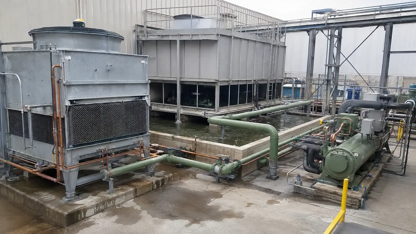
Use the comparison as a scope check rather than a promise of lower operating cost. A wet system may reduce compressor lift in a hot climate, but it also consumes water and requires pump and fan power. A dry system may be preferred where water discharge is restricted, even if the coil or fan bank must be larger. A tower arrangement can be sensible for a central plant with trained water-treatment staff, but it is not a drop-in substitute for an evaporative condenser coil.
Configuration choices: counterflow, combined flow, and crossflow
The airflow and water path influence approach temperature, height, fan arrangement, access, and carryover. Counterflow arrangements move air opposite to the falling water and can make good use of the leaving-air condition, but they need careful drift-eliminator access and fan discharge design. Combined-flow designs use more than one path to balance coil height, airflow, and water distribution. Crossflow layouts can simplify access on some packages, yet they need review of water distribution across the coil face.
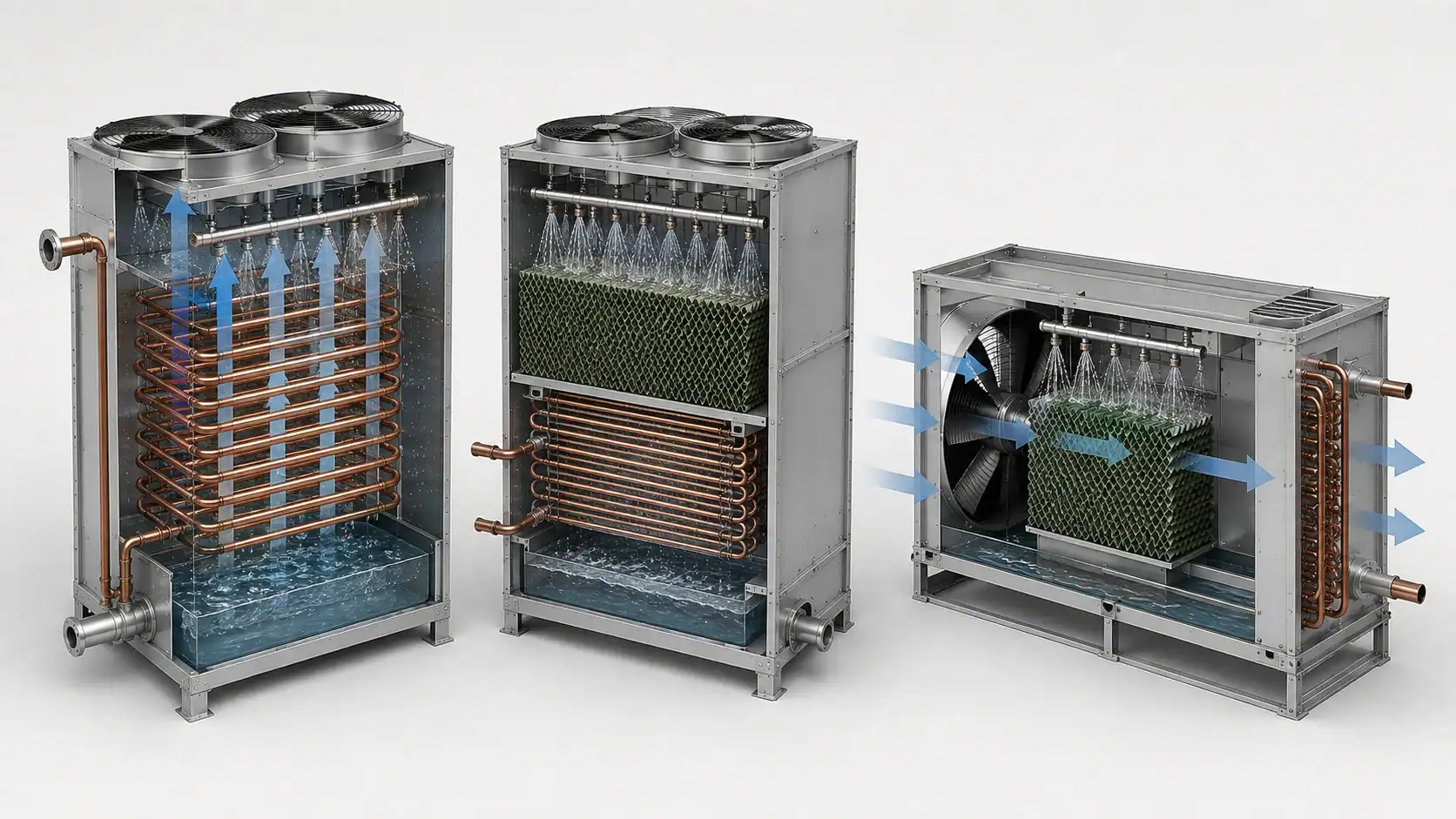
For a counterflow arrangement, review the fan discharge, eliminator removal path, and coil supports. For a combined-flow arrangement, review the balance between sections, headers, and the transition between airflow paths. For a crossflow arrangement, review nozzle coverage, basin zoning, and face clearance. Commissioning should record airflow, spray coverage, drift, wet-bulb approach, capacity split, fan staging, and any dry spots at design flow.
Do not choose a configuration from a catalog sketch without the site layout. Show the prevailing wind, nearby exhausts, walls, service lanes, crane or lifting path, and the direction of refrigerant connections. A package that fits a plan view can still be impossible to inspect if the basin, pump, or drift eliminator cannot be removed.
Water use, blowdown, and treatment
Evaporative-condensing water use has three primary components: evaporation, drift, and blowdown. The make-up balance can be written as:
Makeup water = evaporation + drift + blowdown
Evaporation is the water that changes phase and leaves with the air. Drift is liquid carried out of the package despite the eliminator. Blowdown is intentional discharge used to control dissolved solids. A supplier should provide a design water-flow basis and a control description, but seasonal makeup depends on climate, load profile, cycles of concentration, and the site’s water chemistry.
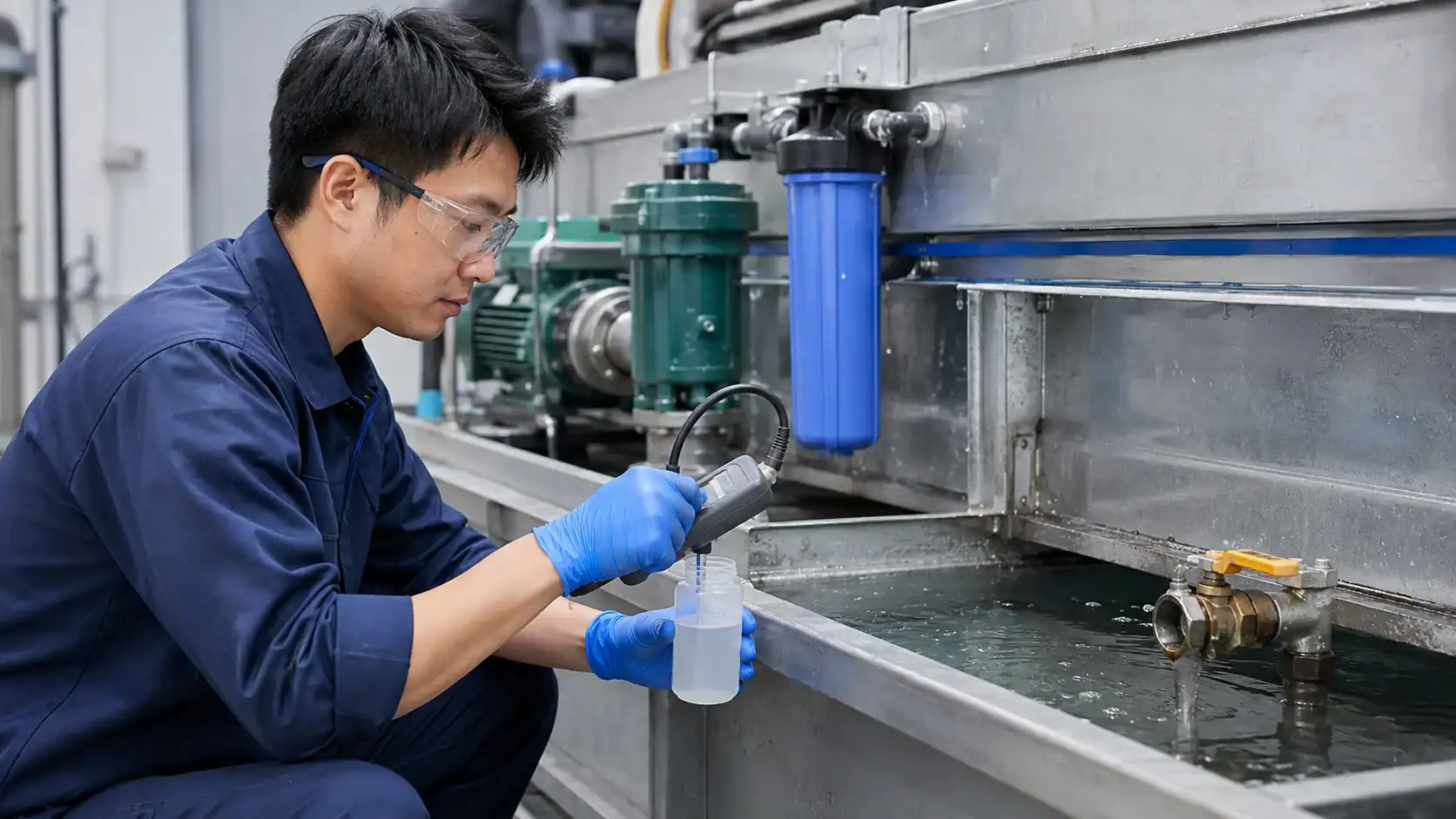
Water treatment is not one universal chemical recipe. The owner and water-treatment specialist should confirm hardness, alkalinity, silica, chlorides, microbiological control, pH, conductivity limits, and discharge requirements. The ASHRAE Handbook guidance explains why scale and corrosion control must be considered together with water consumption and heat-transfer performance. The equipment RFQ should state whether the supplier is providing only the coil, the complete evaporative package, or a recommended treatment interface.
Use a conductivity controller or another defined blowdown strategy when cycles of concentration are part of the design. A basin that is allowed to concentrate salts indefinitely will lose heat-transfer performance and may damage tube surfaces. Excessive blowdown wastes water and can violate site discharge limits. The correct setpoint is a project input based on water analysis and treatment chemistry, not a generic number copied from a different site.
Biological control also belongs in the operating procedure. Define cleaning frequency, inspection ownership, chemical dosing, shutdown and drain-down steps, and the records that prove the procedure was completed. A component supplier can provide cleanable surfaces and access, but the operating company remains responsible for the water-management program and applicable local requirements.
Refrigerant and coil selection inputs
The refrigerant side needs more than a refrigerant name. State the design refrigerant, mass flow or heat-rejection duty, compressor discharge condition, condensing temperature range, allowable pressure drop, subcooling requirement, design pressure, design temperature, and connection standard. If the system may change refrigerants, identify the approved alternatives and their pressure and material implications before the tube and header design is frozen.
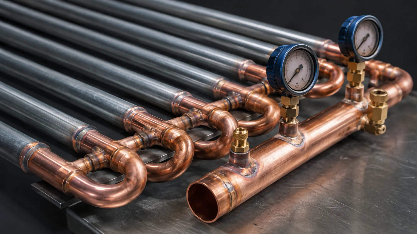
For ammonia or other high-pressure applications, the coil pressure class, weld procedure, non-destructive examination, pressure test, and cleanliness record must match the governing project standard. For halocarbon or CO2 applications, confirm the pressure range at the maximum ambient and any relief or receiver arrangement that affects the coil. Do not infer pressure rating from tube diameter or from a visually similar coil.
Tube material must be checked against water chemistry, refrigerant compatibility, joint method, coating, and cleaning practice. Copper, steel, stainless steel, and treated surfaces each have different fabrication and corrosion considerations. If the coil is a replacement, send photographs of the tube pattern, headers, connection centerlines, supports, and failed areas. A sample can establish fit, but it cannot establish the duty or pressure requirement by itself.
How to size an evaporative condenser
Sizing should begin with a design point and then be tested at part load and adverse ambient conditions. The minimum selection package normally includes:
- Heat rejection duty and compressor heat input, with units and operating point.
- Refrigerant, mass flow or compressor model, suction condition, discharge condition, and desired subcooling.
- Entering air dry bulb and wet bulb, relative humidity, altitude, design wind, and recirculation assumptions.
- Spray water temperature, design flow, water quality, cycles of concentration, and makeup or blowdown limits.
- Coil geometry, pressure class, tube and header material, connection layout, and allowable refrigerant pressure drop.
- Fan airflow, static pressure, motor power, sound limit, speed control, and failure or standby philosophy.
- Site constraints including footprint, access, lifting, structural loads, drains, winter conditions, and service clearance.
For the water side, the familiar liquid heat-balance relationship Q approximately equals m_dot times cp times delta_T can help check a pump and spray flow, but it does not replace the refrigerant enthalpy balance. A refrigerant condenser selection must account for desuperheating, phase change, and possible subcooling. Ask for the supplier’s calculation basis and confirm that the quoted duty uses the same condensing temperature and wet-bulb condition as the project.
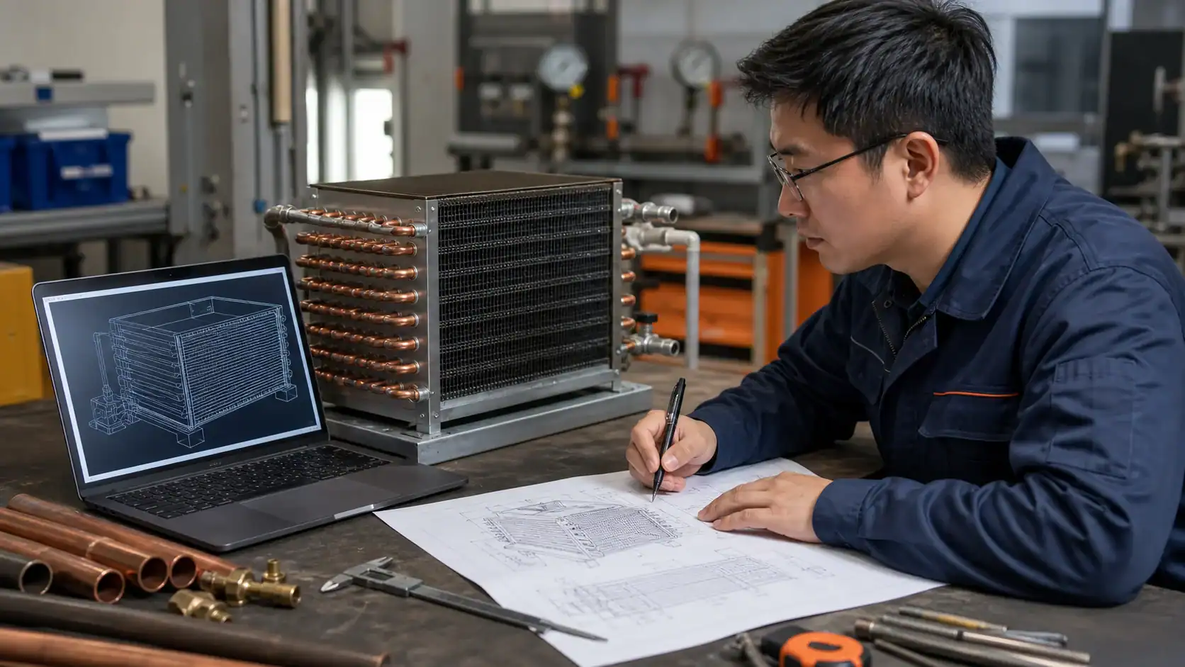
| RFQ input | Why the supplier needs it | Usable response or record |
|---|---|---|
| Refrigerant, mass flow, and heat-rejection duty | Establishes the pressure, enthalpy change, and total heat that must leave the package | Selection sheet with refrigerant state points, duty, condensing temperature, and any subcooling |
| Design wet bulb, dry bulb, altitude, and recirculation | Sets the available evaporative approach and air density | Stated weather basis, air path assumptions, and capacity at design and part load |
| Coil material, pressure, circuiting, and connections | Controls pressure integrity, corrosion risk, fit, pressure drop, and fabrication | Controlled drawing, material callouts, connection schedule, and test standard |
| Water quality, flow, makeup, and blowdown | Determines scale, corrosion, biological control, pump duty, and discharge | Water analysis, treatment interface, cycles basis, and estimated seasonal makeup |
| Fans, sound, controls, and service access | Defines airflow, power, staging, alarms, and maintainability | Fan data, sound method, control sequence, access drawing, and acceptance checks |
| Packaging, inspection, and traceability | Protects the coil and links test records to the supplied component | Inspection plan, pressure or leak record, packing method, revision and lot reference |
Review the selection at the hottest design wet bulb, not only at an annual average. Then ask what happens when a fan is at minimum speed, one nozzle bank is isolated, the basin level is low, the water conductivity is high, or the coil is partially fouled. A robust selection sheet states the control limits and the operator action for each condition.
Maintenance, corrosion, and biological control
Wet surfaces require a more deliberate inspection plan than a dry condenser. Keep the coil, spray nozzles, strainers, drift eliminators, basin, pump, level controls, and blowdown valve on the same maintenance schedule. Record pressure drop, spray pattern, basin condition, conductivity, water temperature, refrigerant condensing temperature, and fan current. Trending those values can show a fouling or distribution problem before capacity is lost.
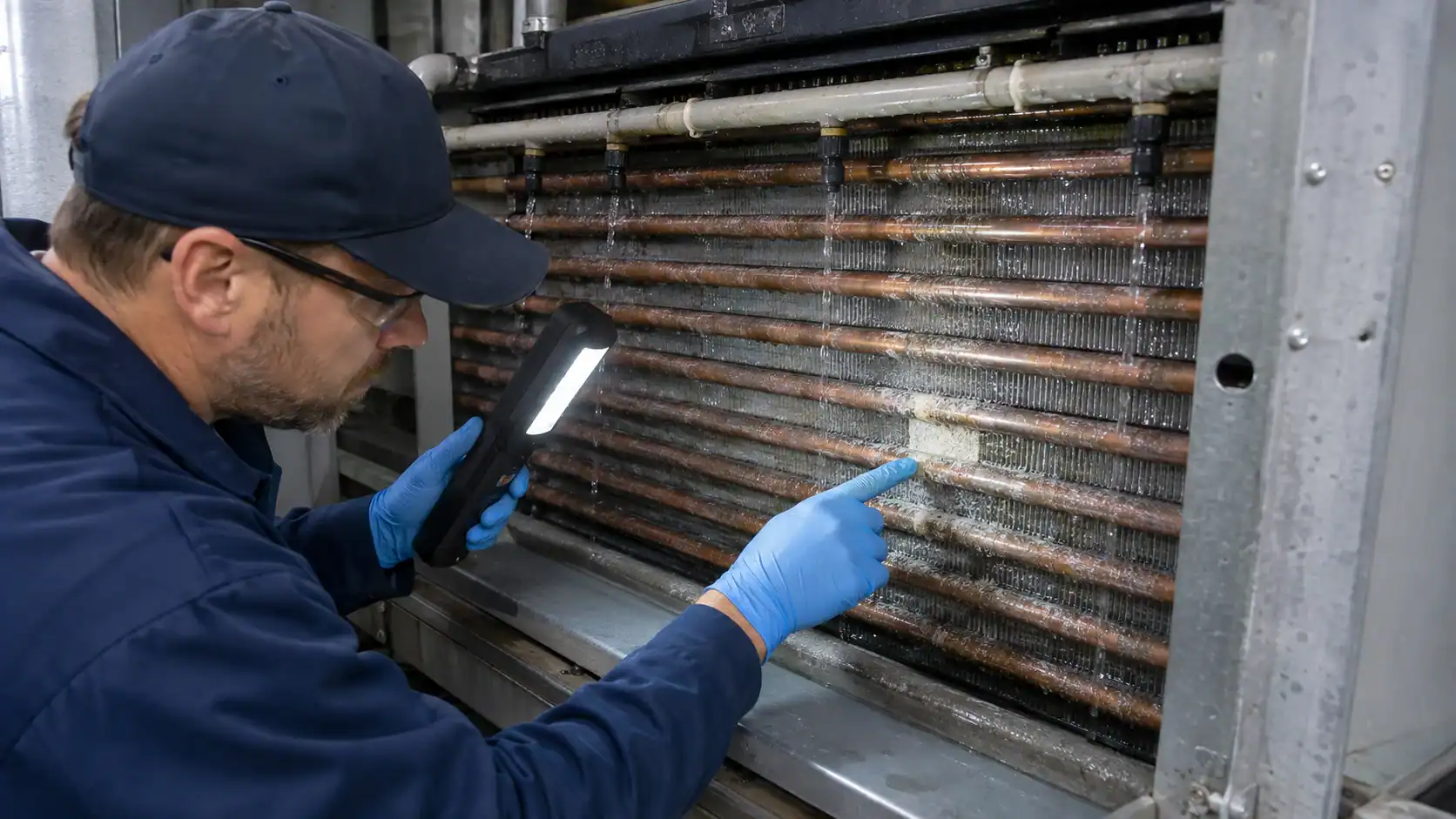
Scale increases thermal resistance and can block nozzles. Corrosion can reduce tube-wall margin, damage headers, or create leaks that contaminate the water circuit. Cleaning chemicals must be compatible with tube material, coatings, elastomers, and the discharge permit. Avoid high-pressure washing that folds fins, damages drift eliminators, or drives debris into the basin pump suction.
Inspect for dry strips, blocked nozzles, uneven water film, damaged eliminator packs, cracked supports, loose fan guards, and basin deposits. Compare the measured condensing temperature with the stated wet-bulb approach. A rising approach with normal refrigerant charge often points toward airflow, water distribution, fouling, or weather recirculation rather than a compressor fault.
The inspection record should identify the equipment tag, date, operator, water readings, chemical actions, parts replaced, and the next planned check. If the equipment is part of a food, pharmaceutical, or other controlled process, link the cleaning and water-treatment records to the site’s quality system. The coil supplier can make inspection easier with removable panels, visible test points, drainable circuits, and a clear drawing, but the owner must maintain the operating program.
Cold-weather and freeze protection
An evaporative condenser can be exposed to freezing air even when the refrigerant system is running. Water trapped in a basin, pump casing, header, nozzle, or low point can expand and damage the assembly. The design should state the lowest ambient, wind exposure, standby duration, drain-down time, heat tracing, recirculation, and restart sequence.
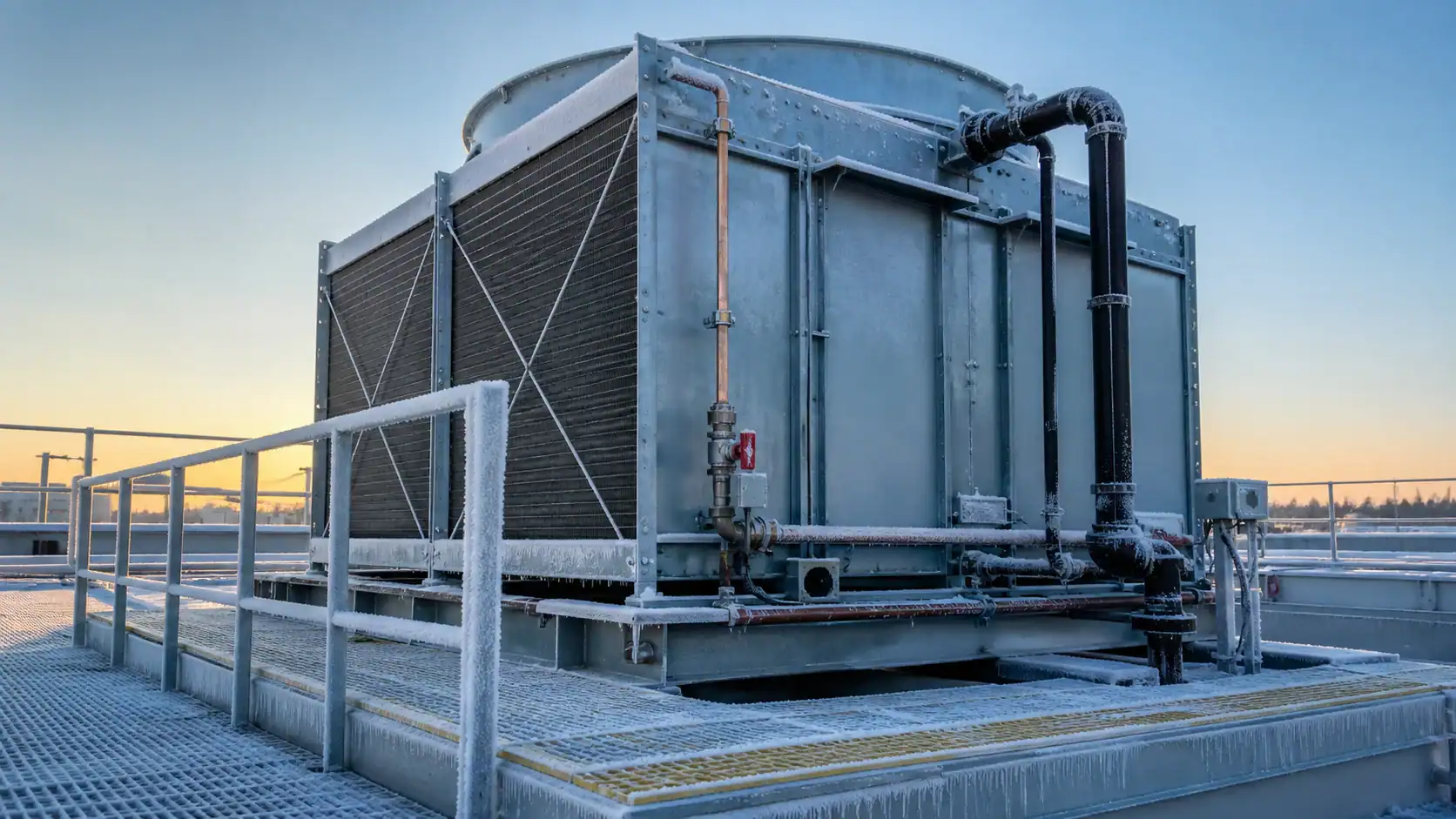
Common protection strategies include full drain-down, a heated basin, heat tracing on vulnerable lines, controlled recirculation, antifreeze in a separate loop, or a combination. Each strategy has consequences for water quality, electrical load, pump seals, and commissioning. A drain valve that is physically low on a drawing may still leave water trapped behind a check valve or in a horizontal header.
| Water or operating risk | Evidence to put in the project file | Owner action before release |
|---|---|---|
| Scale and high conductivity | Water analysis, cycles-of-concentration basis, blowdown setpoint, and cleaning method | Approve treatment chemistry and discharge route with the site specialist |
| Corrosion or incompatible materials | Tube, header, coating, fastener, seal, and chemical compatibility records | Confirm chemistry limits and inspection frequency for the actual site |
| Biological growth | Cleaning and dosing procedure, inspection log, shutdown steps, and responsible person | Assign water-management ownership and keep the required records |
| Freeze exposure | Drain points, trapped-volume review, heat tracing or heated basin data, and restart sequence | Test the low-ambient sequence and verify the basin fully drains |
| Drift and carryover | Eliminator material, carryover basis, access method, and airflow pressure drop | Inspect the eliminator and confirm discharge clearances and nearby intakes |
| Fouling or airflow loss | Coil cleaning method, nozzle and strainer access, fan data, and alarm limits | Record baseline temperatures, flow, pressure drop, and fan current at commissioning |
Supplier evidence and the Domi component path
An evaporative condenser is a complete heat-rejection package, but an OEM may be buying only the refrigerant coil or a replacement coil assembly. Separate those scopes in the RFQ. Identify who owns the fans, spray pump, basin, controls, frame, water treatment, performance guarantee, and site commissioning. That prevents a coil supplier from being held responsible for a fan or water-control problem that was never in its supply.
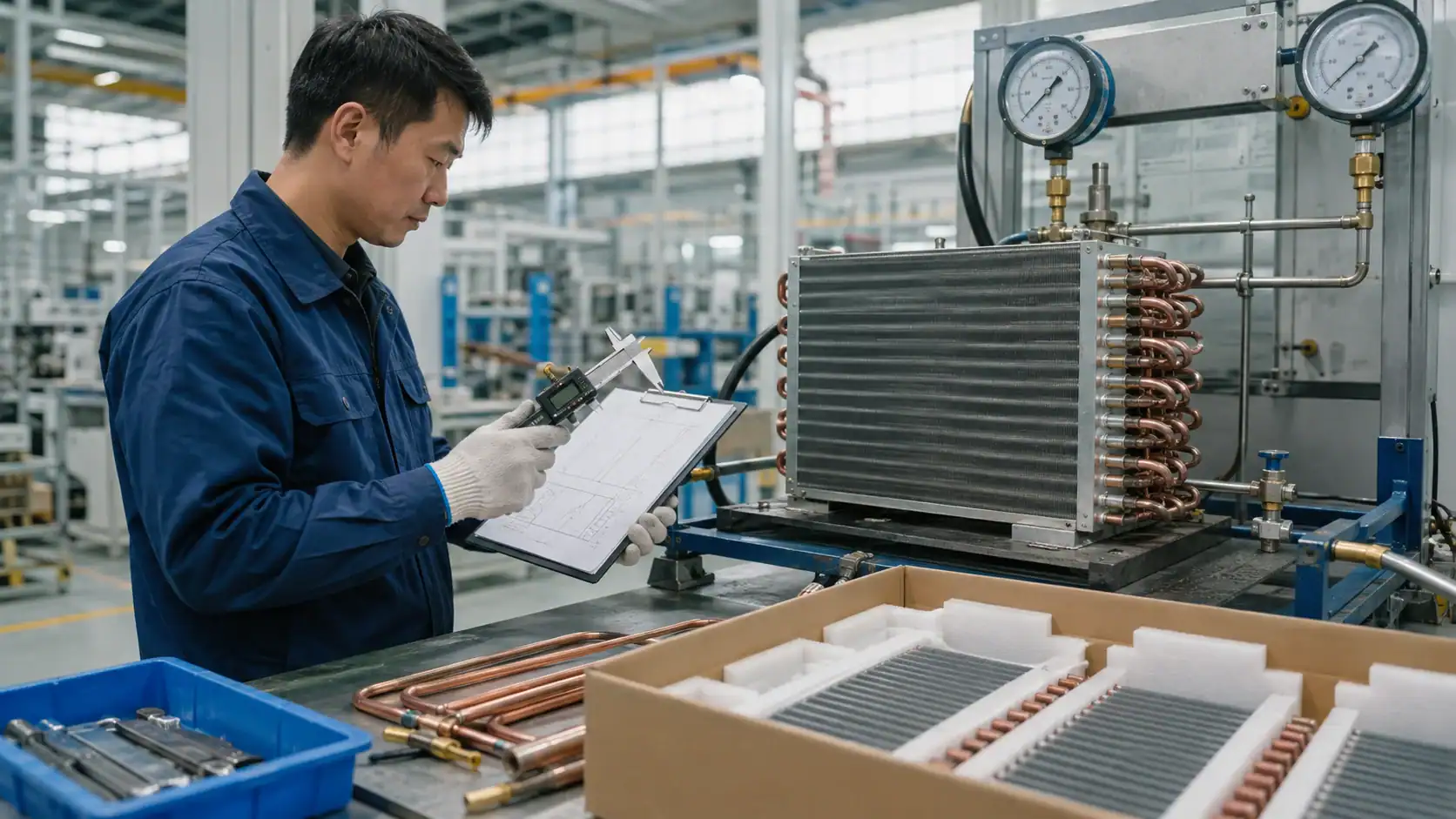
For a coil-focused inquiry, include the controlled drawing or a usable sample, refrigerant and pressure conditions, duty, connection orientation, tube and header materials, supports, leak or pressure-test requirement, surface treatment, inspection records, packaging, and required delivery date. Add photographs of the existing equipment and the failed part when the project is a replacement. Mark the revision that should govern the quote.
The Domi path is component-focused. Domi custom coil fabrication is the appropriate starting point for a custom condenser-coil review, while the Domi engineering capabilities page explains the drawing and thermal-engineering route. Use the Domi testing lab page when pressure, leak, dimensional, or other inspection records are required. Domi should not be presented as the supplier of a complete evaporative condenser package unless a separate project specification confirms the fan, spray, basin, controls, frame, and performance scope.
From approved selection to production release
After the thermal selection is accepted, freeze the design inputs before issuing a production purchase order. Link the thermal sheet, drawing revision, bill of materials, inspection plan, pressure or leak record, and packaging instructions. For a prototype, compare fit-up, connections, measured pressure drop, and test results with the approved revision before repeating production.
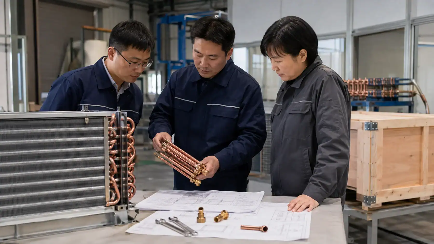
Ask the supplier to identify the inspection point for each critical feature: tube and header material, connection centerline, circuiting, support location, pressure test, cleanliness, coating or corrosion protection, and packing restraint. On export shipments, protect headers and connections from impact and keep lifting loads away from tube bends. Photograph the packed assembly when the receiving team will use the record for incoming inspection.
The final handoff should allow a technician to answer five questions without searching through email: which drawing revision was built, which refrigerant and duty were used, which test covers the component, which materials were supplied, and which site conditions limit the rating. If a future replacement is likely, retain the coil drawing, nameplate data, test record, and image of the installed connection layout with the equipment file.
Frequently asked questions
What is an evaporative condenser?
An evaporative condenser is a refrigeration heat-rejection device that condenses hot refrigerant inside a coil while spray water and moving air remove heat from the coil surface. It combines a pressure-rated refrigerant circuit with a separate recirculating water circuit and an airflow path.
How does an evaporative condenser work?
Hot refrigerant vapor enters the coil, water is sprayed over the outside, and fans move air through the wetted assembly. Some water evaporates, carrying away heat. Unevaporated water returns to the basin, while liquid refrigerant leaves the coil after desuperheating and condensation.
How is it different from a cooling tower?
An evaporative condenser contains the refrigerant coil in the evaporative package. A cooling tower normally cools an open or semi-open water loop, and a separate water-cooled condenser transfers refrigerant heat into that loop. The two options have different pressure, piping, treatment, controls, and maintenance boundaries.
Does an evaporative condenser use water?
Yes. Water is used for evaporation and recirculation, and additional makeup replaces evaporation, drift, and blowdown. The actual seasonal quantity depends on heat load, wet-bulb conditions, cycles of concentration, water treatment, and operating hours, so the supplier should state the design basis rather than promise a universal water rate.
Is an evaporative condenser more efficient than an air-cooled condenser?
It can operate at a lower condensing temperature in suitable wet-bulb conditions, which may reduce compressor lift. It also adds pump power, fan power, water consumption, treatment, and maintenance. Compare the complete system at the project’s weather, water, electricity, sound, and service constraints rather than comparing a single catalog capacity number.
What should an OEM include in an evaporative condenser RFQ?
Include refrigerant, heat-rejection duty, mass flow or compressor data, condensing and subcooling requirements, design wet bulb and dry bulb, altitude, water analysis, spray flow, blowdown limits, coil material and pressure class, circuiting, connections, fans, sound, controls, service access, inspection, packaging, and the controlled drawing revision. For a replacement coil, attach a sample or dimensioned drawing and photographs of the existing connections.