Quick answer: HVAC symbols identify equipment, air paths, piping, control points, and operating conditions on plans, schematics, schedules, and submittals. Common examples include AHU for air-handling unit, SA for supply air, CHWS for chilled-water supply, TXV for thermostatic expansion valve, SST for saturated suction temperature, and VFD for variable-frequency drive. Always read the project legend first because the same code can carry a different meaning on another drawing.
A drawing can look precise and still be easy to misread. HP may mean heat pump on an equipment schedule and horsepower beside a motor. DP may mean dew point on a psychrometric sheet or differential pressure on a control diagram. DO may mean digital output in a controls list, while an architectural note could use it differently.
Below, the 112 terms are grouped by the place you are most likely to encounter them. The aim is practical: help engineers, equipment designers, procurement teams, and technicians review a drawing or prepare a coil inquiry without guessing.
One boundary matters. This list covers text codes, units, and short labels. Graphical shapes are a separate layer. Mechanical offices, manufacturers, and software libraries may draw the same component differently, so the legend on the issued document remains the controlling reference.
How to read HVAC symbols without guessing
Use this five-step check before assigning a meaning to any abbreviation:
- Find the legend. Look for a symbol key, abbreviation schedule, general notes, or standard detail sheet.
- Identify the document type. A plan, P&ID, wiring diagram, sequence of operation, equipment schedule, and coil drawing use different vocabularies.
- Trace the connected system. A code beside ductwork, hydronic piping, refrigerant tubing, or a control wire gains meaning from its connections.
- Check the units. Temperature, pressure, airflow, water flow, and capacity values can reveal what a nearby code represents.
- Confirm the revision. Use the issued revision and its matching schedules. A revised coil duty with an old piping diagram can create a technically consistent-looking but incorrect package.
ASHRAE Terminology provides a broad vocabulary reference for HVAC and refrigeration. ISO 14617-1 covers general rules for graphical symbols used in diagrams. Neither removes the need to follow the legend and notes on the actual project drawing.
112 HVAC and refrigeration symbols at a glance
Equipment and packaged-unit abbreviations
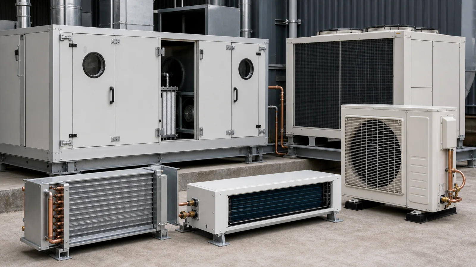
These labels usually appear on floor plans, roof plans, equipment schedules, control diagrams, and submittals. The tag may be followed by a number, such as AHU-2 or RTU-5, to identify one specific unit.
| No. | Symbol | Meaning | Where it appears and what to check |
|---|---|---|---|
| 1 | AHU | Air-handling unit | Conditions and moves air through filters, coils, dampers, and fans. Match the tag to the schedule before using its airflow or coil duty. |
| 2 | RTU | Rooftop unit | A packaged unit installed on a roof or curb. Confirm cooling type, heating source, outside-air requirement, electrical data, and curb arrangement. |
| 3 | FCU | Fan coil unit | A fan and coil assembly serving a room or zone. Check whether the coil uses chilled water, hot water, glycol, or refrigerant. |
| 4 | MAU | Makeup air unit | Supplies air to replace exhaust or process air. Its load may be driven by outdoor design conditions rather than return-air conditions. |
| 5 | DOAS | Dedicated outdoor air system | Treats outdoor ventilation air separately from zone sensible loads. Confirm supply condition, recovery device, and downstream terminal strategy. |
| 6 | FAHU | Fresh air-handling unit | A regional or project-specific term for an air handler focused on outdoor air. Verify whether it is equivalent to an MAU or DOAS in the legend. |
| 7 | ERV | Energy recovery ventilator | Transfers sensible and usually latent energy between exhaust and outdoor air streams. Check recovery type, leakage limits, and frost strategy. |
| 8 | HRV | Heat recovery ventilator | Commonly transfers sensible heat between air streams. The exact distinction from ERV should be confirmed from the schedule. |
| 9 | CU | Condensing unit | Usually includes a compressor and condenser. CU can be ambiguous, so verify whether the project uses it for condensing unit, control unit, or another item. |
| 10 | ACU | Air-conditioning unit | A general equipment label whose scope varies widely. Read the schedule to determine whether it is split, packaged, air cooled, or water cooled. |
| 11 | HP | Heat pump | Often identifies reversible heating and cooling equipment. Near motors, hp may instead mean horsepower, so capitalization and context matter. |
| 12 | WSHP | Water-source heat pump | Exchanges heat with a water loop. Confirm loop entering-water range, water flow, pressure drop, and condensate requirements. |
| 13 | VRF | Variable refrigerant flow | A multi-zone direct-expansion system with modulated refrigerant flow. Confirm branch arrangement, equivalent piping length, and manufacturer rules. |
| 14 | VRV | Variable refrigerant volume | A manufacturer-associated name often used for a VRF system. Do not assume the terms are interchangeable in a proprietary specification. |
| 15 | CRAC | Computer room air conditioner | Precision cooling equipment with an active refrigeration circuit. Check air-delivery pattern, redundancy, humidity control, and heat-rejection method. |
| 16 | CRAH | Computer room air handler | Precision air-handling equipment typically connected to chilled water. Confirm coil duty, water temperatures, fan control, and underfloor or overhead delivery. |
Airside and duct-system abbreviations
Airside codes describe where air came from, where it is going, and how much of it moves through a duct or unit. The same fan can have several airflow values, so distinguish scheduled design airflow from measured or minimum airflow.
| No. | Symbol | Meaning | Where it appears and what to check |
|---|---|---|---|
| 17 | SA | Supply air | Conditioned air leaving a unit or terminal for the served space. Confirm whether the noted temperature is at the coil, unit, or room diffuser. |
| 18 | RA | Return air | Air returning from a space to equipment. A return path may include ceiling plenums, ductwork, transfer grilles, and relief paths. |
| 19 | OA | Outdoor air | Air brought into the system from outdoors. Check design temperature, humidity, minimum ventilation rate, and intake location. |
| 20 | EA | Exhaust air | Air discharged from a building or process. Do not confuse it with relief air, which may vary with building pressure. |
| 21 | FA | Fresh air | Often means outdoor ventilation air, but some drawings use another definition. The legend should confirm whether FA and OA are equivalent. |
| 22 | MA | Mixed air | The mixture of outdoor and return air entering a coil or air handler. Mixed-air conditions are important inputs for coil selection. |
| 23 | TA | Transfer air | Air moving from one space to another without being directly supplied there. Check pressure relationships and code requirements for the opening or duct. |
| 24 | CFM | Cubic feet per minute | An airflow unit used in inch-pound practice. Confirm whether the value is actual, standard, design, minimum, or measured airflow. |
| 25 | L/s | Litres per second | An SI-derived airflow unit. Case and slash placement matter because unit symbols follow conventions rather than ordinary plural abbreviations. |
| 26 | ACH | Air changes per hour | Room airflow divided by room volume on an hourly basis. Confirm whether the calculation uses supply, exhaust, outdoor, or recirculated air. |
| 27 | FPM | Feet per minute | Air velocity used for duct, grille, filter, and coil-face checks. High face velocity can affect pressure drop and moisture carryover. |
| 28 | ESP | External static pressure | Resistance outside a packaged unit or fan section. Check which accessories and duct sections are included in the stated boundary. |
| 29 | TSP | Total static pressure | A broader static-pressure requirement for a fan or system. The measurement reference points must match the fan selection. |
| 30 | VAV | Variable air volume | A system or terminal that varies airflow. Review minimum flow, reheat, ventilation control, and sound limits. |
| 31 | CAV | Constant air volume | A system or terminal intended to maintain a set airflow. The air temperature may still reset or stage. |
| 32 | VCD | Volume control damper | A manual or actuated damper used to regulate airflow. Confirm blade type, size, actuator, access, and required position. |
Hydronic and water-side abbreviations
Hydronic codes often sit beside piping arrows and equipment connections. Supply and return labels can be defined from the plant’s point of view or the connected unit’s point of view, so follow the flow arrows.
| No. | Symbol | Meaning | Where it appears and what to check |
|---|---|---|---|
| 33 | CHWS | Chilled-water supply | Water supplied from the chiller or plant to cooling coils. Record the actual supply temperature used for the coil rating. |
| 34 | CHWR | Chilled-water return | Water returning to the plant after absorbing heat. The difference between CHWR and CHWS drives the required flow. |
| 35 | HWS | Hot-water supply | Heating water delivered to coils or terminal equipment. Confirm temperature, glycol concentration, and control-valve arrangement. |
| 36 | HWR | Hot-water return | Water returning after releasing heat. Low return temperature may affect plant performance and coil sizing. |
| 37 | CWS | Condenser-water supply | Water supplied to a water-cooled condenser, often from a cooling tower. Do not confuse it with chilled-water supply. |
| 38 | CWR | Condenser-water return | Water returning from the condenser to the heat-rejection equipment. Check the drawing’s supply and return convention. |
| 39 | EWT | Entering water temperature | Water or glycol temperature at the equipment inlet. Pair it with entering-air condition, flow, and fluid concentration. |
| 40 | LWT | Leaving water temperature | Fluid temperature at the equipment outlet. It is a result of duty, flow, and heat-exchanger performance. |
| 41 | GPM | Gallons per minute | A volumetric water-flow unit in inch-pound practice. State whether the gallon is the U.S. gallon and identify the fluid. |
| 42 | L/min | Litres per minute | A metric volumetric-flow unit. Keep the unit attached to the value and avoid rewriting it as an informal abbreviation. |
| 43 | ΔT | Temperature difference | The difference between two temperatures. Define the points, such as entering and leaving water, instead of listing a bare delta value. |
| 44 | ΔP | Pressure difference | Pressure loss or differential pressure between two points. Confirm whether the value applies to a coil, valve, circuit, or whole system. |
| 45 | TDH | Total dynamic head | Pump head required to overcome elevation, pressure, velocity, and friction effects for the defined system. Check the calculation boundary. |
| 46 | PHE | Plate heat exchanger | A general plate-type heat exchanger. The schedule should identify gasketed, brazed, welded, or another construction. |
| 47 | BPHX | Brazed-plate heat exchanger | A compact exchanger made from brazed plates. Confirm fluid compatibility, design pressure, fouling risk, and service strategy. |
| 48 | ET | Expansion tank | Accommodates fluid-volume change in a closed hydronic system. Check connection point, precharge, acceptance volume, and pressure rating. |
Refrigeration component abbreviations
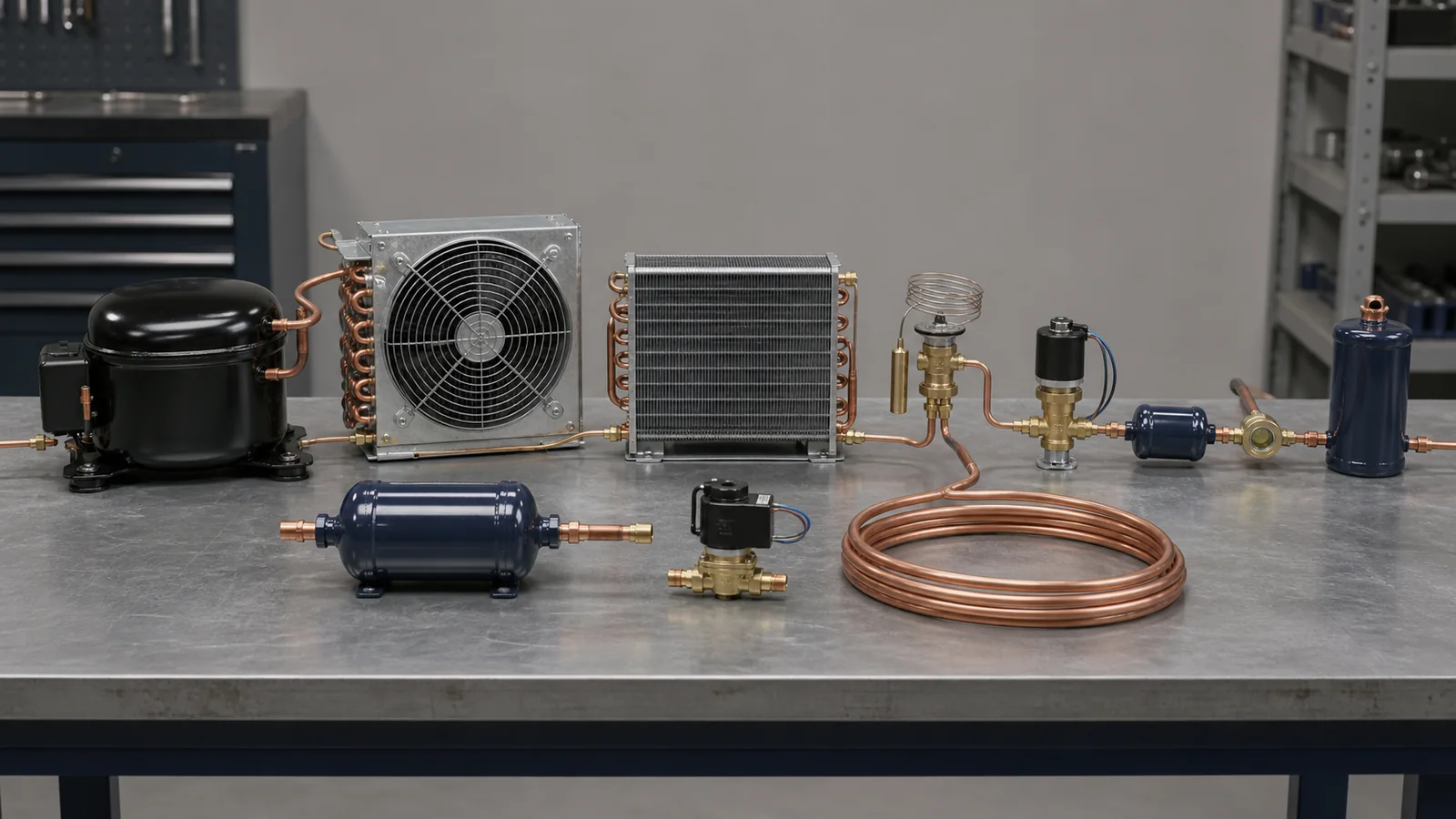
These codes are common on refrigeration schematics, P&IDs, equipment schedules, control sequences, and service documentation. The same component can be drawn with different shapes, but its connected piping often reveals its function.
| No. | Symbol | Meaning | Where it appears and what to check |
|---|---|---|---|
| 49 | COMP | Compressor | Raises refrigerant vapor pressure and temperature. Confirm refrigerant, capacity point, speed control, oil management, and operating envelope. |
| 50 | COND | Condenser | Rejects heat and condenses refrigerant. The abbreviation can refer to a coil, shell-and-tube unit, or complete heat-rejection section. |
| 51 | EVAP | Evaporator | Absorbs heat while refrigerant evaporates. Check application temperature, feeding method, superheat control, frost, and drainage. |
| 52 | TXV | Thermostatic expansion valve | Meters refrigerant using a thermostatic sensing element. Confirm refrigerant, capacity, equalizer, charge, and selected superheat range. |
| 53 | TEV | Thermostatic expansion valve | An alternate abbreviation for TXV. Use the project or manufacturer convention consistently rather than assuming a different device. |
| 54 | EEV | Electronic expansion valve | Meters refrigerant under electronic control. Confirm driver, step count or signal, control logic, and fail position. |
| 55 | LLSV | Liquid-line solenoid valve | Opens or closes liquid refrigerant flow. Check voltage, pressure differential, flow direction, capacity, and pump-down sequence. |
| 56 | RV | Reversing valve | Redirects refrigerant flow in a heat pump. RV can also mean relief valve, so trace the ports and read the schedule. |
| 57 | F/D | Filter drier | Removes contaminants and moisture from the refrigerant circuit. Confirm line location, flow direction, size, and replaceable or sealed construction. |
| 58 | SG | Sight glass | Provides a visual condition indicator, often with a moisture element. Interpret bubbles only in the context of load, subcooling, and system state. |
| 59 | LR | Liquid receiver | Stores liquid refrigerant and helps manage charge. Check volume, orientation, design pressure, valves, and applicable safety requirements. |
| 60 | ACC | Suction accumulator | Helps prevent liquid refrigerant from reaching the compressor. Verify oil return, pressure drop, volume, and orientation. |
| 61 | O/S | Oil separator | Separates oil from discharge gas and returns or manages it. The return method and pressure conditions affect selection. |
| 62 | O/R | Oil reservoir | Holds oil for distribution in a multi-compressor or managed oil system. Check level controls, pressure regulation, and connections. |
| 63 | CPR | Crankcase pressure regulator | Limits compressor suction pressure under high-load conditions. Confirm setpoint, capacity, and interaction with other controls. |
| 64 | EPR | Evaporator pressure regulator | Maintains a minimum evaporator pressure upstream of the valve. It is often used when evaporators operate at different temperatures. |
Refrigerant piping and operating-condition codes
This group contains some of the most consequential labels in a coil selection. A pressure or temperature value without its reference condition can move the design point enough to change circuiting, tube count, and control selection.
| No. | Symbol | Meaning | Where it appears and what to check |
|---|---|---|---|
| 65 | SL | Suction line | Carries low-pressure vapor from the evaporator toward the compressor. Check velocity, oil return, insulation, slope, and pressure drop. |
| 66 | DL | Discharge line | Carries high-pressure vapor from the compressor. Review temperature, oil transport, vibration, supports, and pressure rating. |
| 67 | LL | Liquid line | Carries condensed liquid refrigerant toward the metering device. Pressure drop and heat gain affect available subcooling. |
| 68 | HGL | Hot-gas line | Carries hot discharge gas for defrost, reheat, capacity control, or another function. Define its operating modes and controls. |
| 69 | SST | Saturated suction temperature | Saturation temperature corresponding to suction-side pressure for the stated refrigerant. Do not substitute measured suction-line temperature. |
| 70 | SCT | Saturated condensing temperature | Saturation temperature corresponding to condensing-side pressure. State whether a dew or bubble reference is used for a blend. |
| 71 | SH | Superheat | Vapor temperature above saturation temperature at the same pressure. Identify whether the value is at the evaporator outlet or compressor inlet. |
| 72 | SC | Subcooling | Liquid temperature below saturation temperature at the same pressure. Identify the measurement location and refrigerant reference. |
| 73 | TD | Temperature difference | A general difference between two named temperatures. It may mean room-to-evaporating, air-to-fluid, or another project-defined pair. |
| 74 | psig | Pounds per square inch, gauge | Pressure measured relative to local atmospheric pressure. Use the lowercase unit style shown in the project standard. |
| 75 | psia | Pounds per square inch, absolute | Pressure measured relative to a vacuum. It is not interchangeable with gauge pressure in thermodynamic calculations. |
| 76 | kPa | Kilopascal | An SI pressure unit. Unit symbols are not pluralized and normally do not take a period. |
| 77 | bar | Bar | A pressure unit used in many refrigeration documents. State whether any reading is gauge or absolute when the distinction matters. |
| 78 | DP | Dew point | The temperature at which vapor begins to condense under the stated condition. DP may also mean differential pressure, so context is essential. |
| 79 | BP | Bubble point | For a refrigerant blend, the condition at which the first bubble of vapor forms from liquid. BP can have other project meanings. |
| 80 | P-T | Pressure-temperature relationship | A table or chart linking refrigerant saturation pressure and temperature. Use the correct refrigerant and dew or bubble column where applicable. |
For refrigerant numbering and safety-classification context, use the ASHRAE refrigerant-designation resources. A refrigerant label alone does not define the complete safety, charge, ventilation, or code strategy for an installation.
Psychrometric and performance abbreviations
Air-coil performance depends on both dry-bulb temperature and moisture condition. A coil RFQ that supplies only room temperature may not contain enough information to predict latent capacity, condensate, or leaving-air condition.
| No. | Symbol | Meaning | Where it appears and what to check |
|---|---|---|---|
| 81 | DB | Dry-bulb temperature | The ordinary air temperature measured without an evaporative wet-bulb effect. Pair it with humidity information. |
| 82 | WB | Wet-bulb temperature | A temperature influenced by evaporative cooling. Confirm whether the value is measured, calculated, or a design condition. |
| 83 | RH | Relative humidity | The ratio of actual water-vapor pressure to saturation vapor pressure at the same temperature. It changes when air temperature changes. |
| 84 | h | Specific enthalpy | Energy per unit mass used in psychrometric and refrigeration calculations. Do not confuse lowercase h with an hour symbol in another context. |
| 85 | W | Humidity ratio | Mass of water vapor per mass of dry air. Some documents use w, x, or another symbol, so check the chart legend. |
| 86 | SHR | Sensible heat ratio | Sensible capacity divided by total capacity. It helps describe how a cooling coil divides temperature and moisture removal. |
| 87 | BF | Bypass factor | A model of the fraction of air that behaves as though it did not reach the coil surface condition. It is tied to coil geometry and airflow. |
| 88 | ADP | Apparatus dew point | The effective coil-surface saturation point found by extending the air-conditioning process line. It is a performance model, not one measured spot. |
| 89 | EAT | Entering air temperature | Air temperature at the equipment or coil inlet. State dry-bulb plus wet-bulb, RH, or dew point as needed. |
| 90 | LAT | Leaving air temperature | Air temperature at the equipment or coil outlet. Clarify whether it is coil-off, unit-discharge, or space-supply temperature. |
| 91 | RAT | Return air temperature | Temperature of air returning from the served zone. It can differ from the coil entering condition when outdoor air is mixed in. |
| 92 | SAT | Supply air temperature | Temperature of air delivered by the system. SAT may also be read as saturation temperature in refrigeration notes, so check the sheet type. |
| 93 | COP | Coefficient of performance | Useful heating or cooling effect divided by energy input on a consistent basis. State the operating condition and included auxiliaries. |
| 94 | EER | Energy efficiency ratio | Cooling capacity divided by electrical input at a specified rating condition. Do not compare values measured under different conditions. |
| 95 | SEER2 | Seasonal energy efficiency ratio 2 | A seasonal cooling-efficiency metric for covered equipment under the applicable test procedure. It is not a single design-point coil rating. |
| 96 | HSPF2 | Heating seasonal performance factor 2 | A seasonal heating-efficiency metric for covered heat-pump equipment. Climate and test assumptions differ from a project design point. |
The U.S. Department of Energy explains SEER2 and purchasing requirements for covered central air conditioners. For a custom coil, the thermal duty, air and fluid conditions, pressure-drop limits, and cabinet constraints still need to be stated directly.
Controls, electrical, and point-list abbreviations
Controls drawings connect physical equipment to sensors, commands, alarms, and sequences. A point name can be correct while the device range, signal type, or fail action is still missing.
| No. | Symbol | Meaning | Where it appears and what to check |
|---|---|---|---|
| 97 | BAS | Building automation system | The supervisory control system for building equipment. Define required points, network, trends, alarms, and responsibility boundaries. |
| 98 | BMS | Building management system | Often used similarly to BAS, sometimes with broader facility functions. Follow the project’s definition rather than assuming exact equivalence. |
| 99 | DDC | Direct digital control | Digital control of equipment or systems through programmable controllers. Review sensors, outputs, sequences, and fallback behavior. |
| 100 | PLC | Programmable logic controller | An industrial controller used for machines, skids, or plant processes. Confirm I/O, communications, program ownership, and safety separation. |
| 101 | VFD | Variable-frequency drive | Controls AC motor speed by varying frequency and voltage. Check motor compatibility, enclosure, bypass, harmonics, and minimum speed. |
| 102 | ECM | Electronically commutated motor | A motor with integrated electronic commutation, common in fans and pumps. Verify control signal, speed range, and programmed behavior. |
| 103 | PID | Proportional-integral-derivative control | A feedback-control method that responds to current, accumulated, and changing error. Tuning depends on the controlled process. |
| 104 | SP | Setpoint | The target value for a control loop. SP may also mean static pressure, so look at the point name and units. |
| 105 | PV | Process variable | The measured value being controlled or monitored. Confirm sensor location, range, scaling, and units. |
| 106 | AI | Analog input | A continuously varying input to a controller, such as temperature or pressure. In other contexts, AI may have a different meaning. |
| 107 | AO | Analog output | A modulating command from a controller, such as a valve or drive signal. State the signal type and fail response. |
| 108 | DI | Digital input | A discrete status input, such as proof, alarm, or contact state. Define what open and closed mean. |
| 109 | DO | Digital output | A discrete command output, such as start, stop, enable, or relay operation. Confirm interlocks and whether the output is maintained or pulsed. |
| 110 | HOA | Hand-off-auto | A selector that permits manual command, disables the command, or returns control to the automatic sequence. Define where each mode is active. |
| 111 | NC | Normally closed | A contact or valve state under the stated normal condition. The normal condition must be defined as de-energized, unpowered, or another basis. |
| 112 | NO | Normally open | A contact or valve state under the stated normal condition. Verify fail position separately because normal and fail states are not always identical. |
Unit symbols are not ordinary abbreviations
Codes such as AHU and TXV are abbreviations. Symbols such as kPa, L/s, and °C represent units. That distinction changes how they should be written.
The NIST SI style guide explains that unit symbols are mathematical entities. They are normally not pluralized, and they are not followed by a period unless they end a sentence. That is why 20 kPa is correct while 20 kPas is not.
The same discipline helps in an RFQ. Keep the value and unit together, preserve capitalization, and state whether pressure is gauge or absolute. If a schedule mixes inch-pound and SI values, identify which column controls and check the conversion rather than assuming the displayed values are equivalent.
Common symbol conflicts that deserve a second look
| Code | Meaning 1 | Meaning 2 | Safe resolution |
|---|---|---|---|
| HP | Heat pump | Horsepower | Check whether the code is an equipment tag or a motor rating. |
| CU | Condensing unit | Control unit or project-specific tag | Trace connected refrigerant piping and match the equipment schedule. |
| RV | Reversing valve | Relief valve | Review port count, line location, and component schedule. |
| DP | Dew point | Differential pressure | Check the units and whether the sheet is psychrometric or controls-focused. |
| SAT | Supply air temperature | Saturation temperature | Check the point list, refrigerant notes, and associated units. |
| SP | Setpoint | Static pressure | Read the full point name and measurement location. |
| NC | Normally closed | No cooling or another local shorthand | Read the legend and sequence of operation. |
| OA | Outdoor air | Overall dimension or local shorthand | Check whether the code sits on ductwork or a fabrication detail. |
If a code is still unclear, do not quietly guess. Add a question to the submittal or RFQ, cite the sheet and detail, and ask the responsible party to confirm the intended meaning.
What to include when a symbol list becomes a coil RFQ

A marked drawing is useful, but a buildable coil inquiry needs more than tags. For a replacement or custom HVAC coil, include the following where applicable:
- equipment tag and drawing revision
- coil function, such as evaporator, condenser, chilled-water, hot-water, steam, or heat-recovery duty
- refrigerant or fluid, including concentration where a glycol mixture is used
- entering and leaving air conditions
- entering and leaving fluid conditions
- airflow and allowed airside pressure drop
- fluid flow and allowed fluid-side pressure drop
- total and sensible capacity targets
- saturated suction and condensing conditions for direct-expansion or condenser duties
- superheat or subcooling basis when relevant
- face dimensions, depth, casing limits, tube rows, fin spacing, and connection locations
- material, coating, corrosion exposure, drain-pan, frost, and defrost requirements
- design and test pressure requirements
- quantity, schedule, packaging, and inspection documentation needed
If the old coil is being replaced, add clear photographs, overall dimensions, connection details, circuiting information, and the equipment nameplate. If the project is new, send the design conditions and cabinet constraints before freezing the drawing.
Domi’s engineering capabilities page explains the drawing-review path. The custom coil fabrication and testing laboratory pages show the related manufacturing and validation routes. These links do not replace project specifications, but they help route a technical inquiry to the right team.
Frequently asked questions
Is there one universal set of HVAC symbols?
No. Many symbols and abbreviations are widely recognized, but graphical shapes, tag formats, and short codes vary by office, manufacturer, software library, region, and project. The legend and notes on the issued drawing control the interpretation.
What is the difference between an HVAC symbol and an abbreviation?
A graphical symbol is a shape or line convention representing a component or function. An abbreviation is a shortened text label such as AHU or TXV. A unit symbol such as kPa is a third category with its own writing rules.
How do I read an HVAC drawing for the first time?
Start with the title block, revision, legend, and equipment schedule. Then follow one system at a time from source to terminal. Trace arrows and connections, match tags to schedules, and keep mechanical, electrical, and controls sheets open together.
Why does the same abbreviation have two meanings?
HVAC documents bring several disciplines into a small space. An abbreviation can be reused in equipment, controls, electrical, and psychrometric contexts. Units, connections, sheet type, and the project legend usually resolve the conflict.
What do SST and SCT mean in refrigeration?
SST usually means saturated suction temperature, and SCT usually means saturated condensing temperature. Both depend on the stated refrigerant and pressure reference. They are not the same as measured suction-line or liquid-line temperatures.
What information should I send with a replacement coil drawing?
Send the equipment and coil tags, drawing revision, dimensions, tube and fin details, connection locations, circuiting information, materials, photos, operating conditions, pressure-drop limits, and quantity. Flag any abbreviation that is not defined on the drawing.
Can a supplier size a coil from airflow and dimensions alone?
Usually not with confidence. Airflow and envelope are only part of the duty. The supplier also needs entering and leaving air conditions, fluid or refrigerant conditions, capacity targets, pressure-drop limits, materials, and operating constraints.
Where should I verify refrigerant safety codes?
Use the applicable codes, the current ASHRAE refrigerant designation and safety-classification resources, manufacturer documentation, and the authority having jurisdiction. The U.S. EPA SNAP listings are also relevant for allowed-use context in the United States.
Turn the legend into a buildable coil RFQ
A symbol list helps you decode the document. The useful next step is to turn those codes into named conditions, dimensions, materials, and acceptance requirements. A careful drawing review keeps a short label from becoming an expensive assumption.
Send Your Coil Drawing for Review: mark any uncertain tags, attach the current revision and operating conditions, then use the contact page to request a technical review and quotation route.