
Superheat is the measured vapor temperature minus its saturation temperature at the same pressure. Subcooling is the saturation temperature minus the measured liquid temperature at the same pressure. For refrigerant blends with glide, use the dew value for superheat and the bubble value for subcooling. Compare both readings with the equipment maker’s requirements before diagnosing a fault.
OEM engineers and refrigeration service teams need to decide what to check next. An unexpected reading may call for a probe check or a closer look at refrigerant supply. Adding charge or replacing the evaporator requires more evidence.
This guide covers conventional subcritical direct-expansion refrigeration and cooling systems. It does not apply conventional condenser subcooling calculations to a transcritical CO2 gas cooler. Refrigerant handling and service connections belong to qualified personnel using the equipment manufacturer’s procedure.
The original AI-generated illustrations explain the concepts. They are not Domi factory photographs, measured test results, or installation drawings. Numerical examples are hypothetical.
What do superheat and subcooling measure?
Both quantities are temperature differences referenced to a refrigerant’s saturation condition. They are not the pipe temperature itself, and neither is the air-temperature difference across a coil.
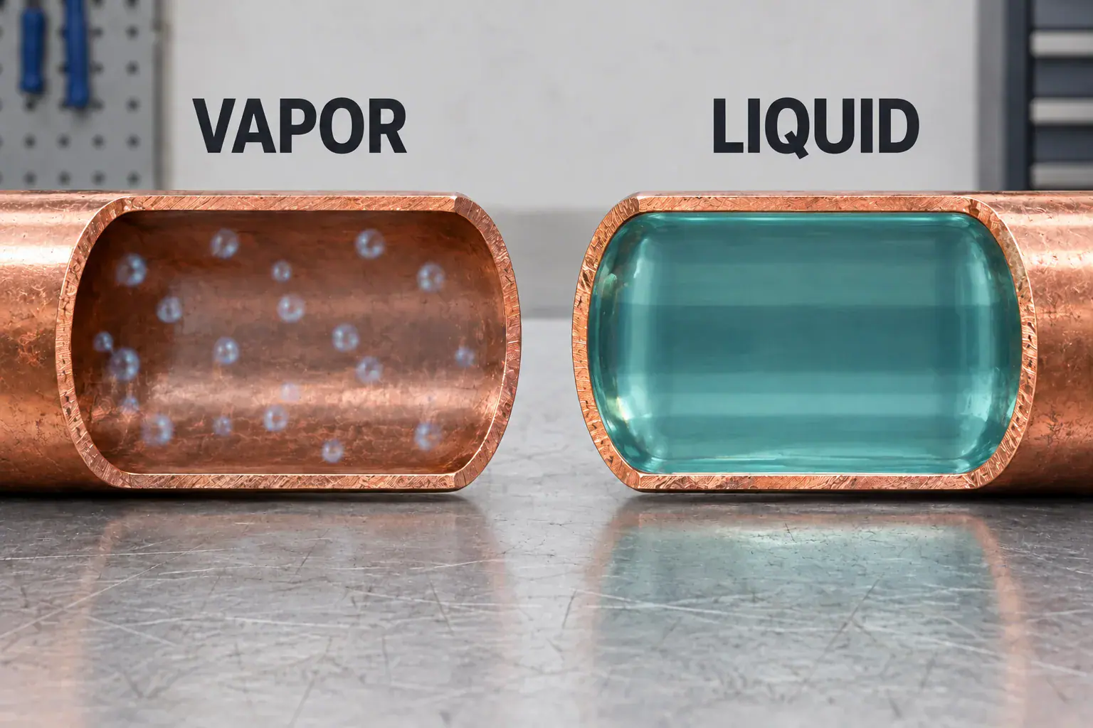
Superheat describes vapor above the saturated-vapor boundary. Subcooling describes liquid below the saturated-liquid boundary. On a single-component refrigerant, there is one saturation temperature at a given pressure. A blend with temperature glide requires the appropriate vapor or liquid reference.
Quantity
Refrigerant condition being assessed
Practical question
Quantity: Superheat
Refrigerant condition being assessed: Vapor relative to local saturated vapor
Practical question: Is the measured outlet condition consistent with the evaporator and compressor requirements?
Quantity: Subcooling
Refrigerant condition being assessed: Liquid relative to local saturated liquid
Practical question: Is there sufficient liquid margin at the point where it is needed?
The refrigerant cycle guide explains the complete circuit. Here, the focus is the measurement record and the decisions it supports.
How do you calculate superheat and subcooling?
Use the refrigerant designation, measured local pressure, and the correct pressure-temperature data to obtain the saturation reference. Then subtract in the correct order:
- Superheat = measured vapor-line temperature − dew saturation temperature.
- Subcooling = bubble saturation temperature − measured liquid-line temperature.
For a pure refrigerant, use its single saturation value. Copeland’s refrigerant changeover bulletin 95-14 demonstrates the calculation using separate vapor and liquid references for R-407C. Do not substitute an air-temperature reading for either refrigerant temperature.
Superheat calculation example
Assume the measured evaporator-outlet pipe temperature is 16°C. The correct P-T lookup at that same location gives a dew temperature of 4°C.
Superheat = 16 − 4 = 12 K.

The result is a 12 K temperature difference. It is not a 12°C pipe temperature, a universal target, or proof of a refrigerant shortage. No actual pressure-to-temperature pair is implied by this teaching example.
Subcooling calculation example
Assume the liquid-line temperature is 35°C. The bubble temperature obtained from the pressure at that same point is 43°C.
Subcooling = 43 − 35 = 8 K.
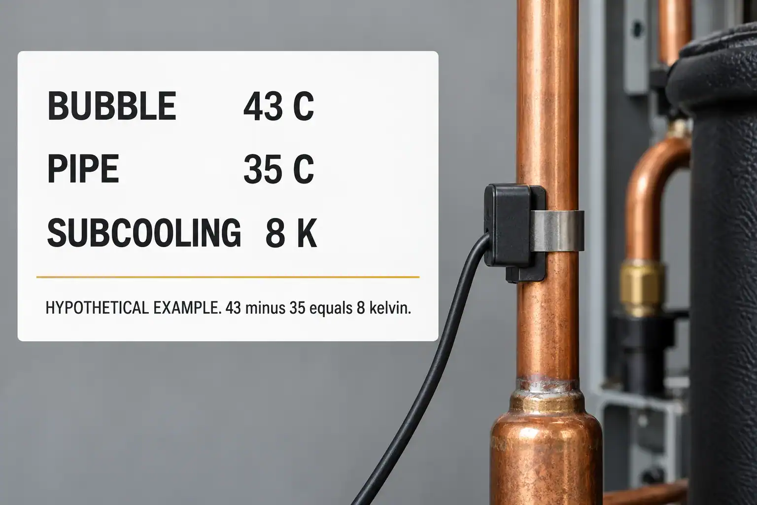
A temperature difference of 1 K equals a difference of 1°C or 1.8°F. Thus, 12 K is 21.6°F of superheat and 8 K is 14.4°F of subcooling. When converting differences, multiply or divide by 1.8; do not add or subtract 32.
Where should pressure and temperature be measured?
Pressure and temperature must describe the same refrigerant location closely enough for the intended calculation. A convenient service port can be a poor substitute when a regulator, long pipe run, or appreciable pressure drop lies between the port and the temperature probe.
For evaporator superheat, identify the outlet measurement point near the sensing bulb or the point specified by the controller maker. For compressor-inlet superheat, use the compressor’s specified suction measurement location. Copeland’s operating measurement guidance explicitly distinguishes those two locations and places the liquid measurement near the metering-device inlet when that is the condition being checked.
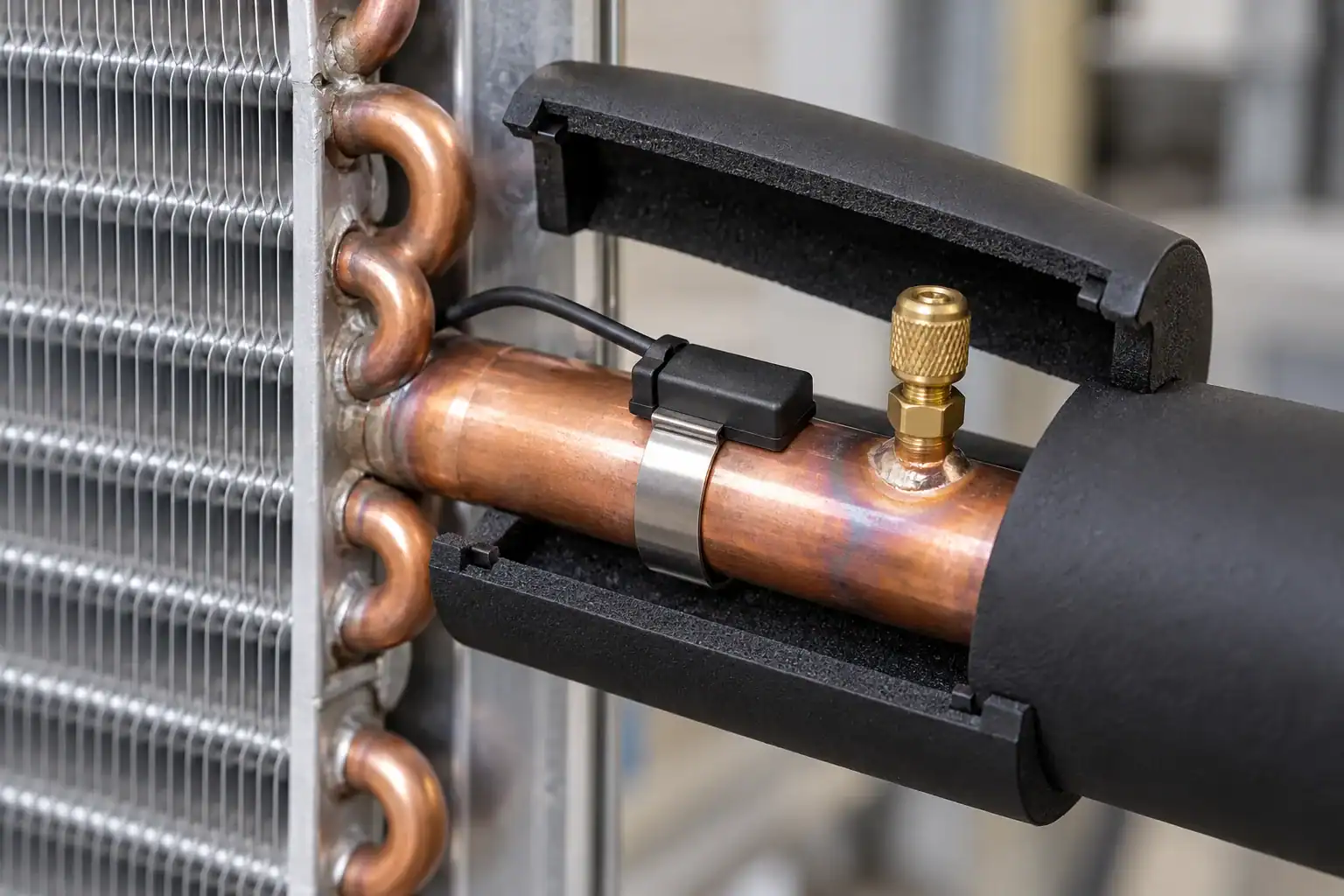
Label the result with its location: “evaporator outlet superheat” or “compressor inlet superheat.” An entry marked only “SH” leaves the next reviewer guessing where it was measured.

Suction-line heat gain and pressure loss can change the saturation margin between these points. A higher compressor-inlet reading does not, by itself, show that the evaporator is underfed. If a pressure regulator separates the locations, record which side of it supplied the pressure reading. Use the refrigerant piping design guide for the separate line-sizing question.
Dew or bubble: which P-T value should you use?
Use dew/saturated vapor for superheat and bubble/saturated liquid for subcooling. A mid-point temperature used for a coil rating is a different reference. It should not silently replace the dew or bubble value in a service calculation.
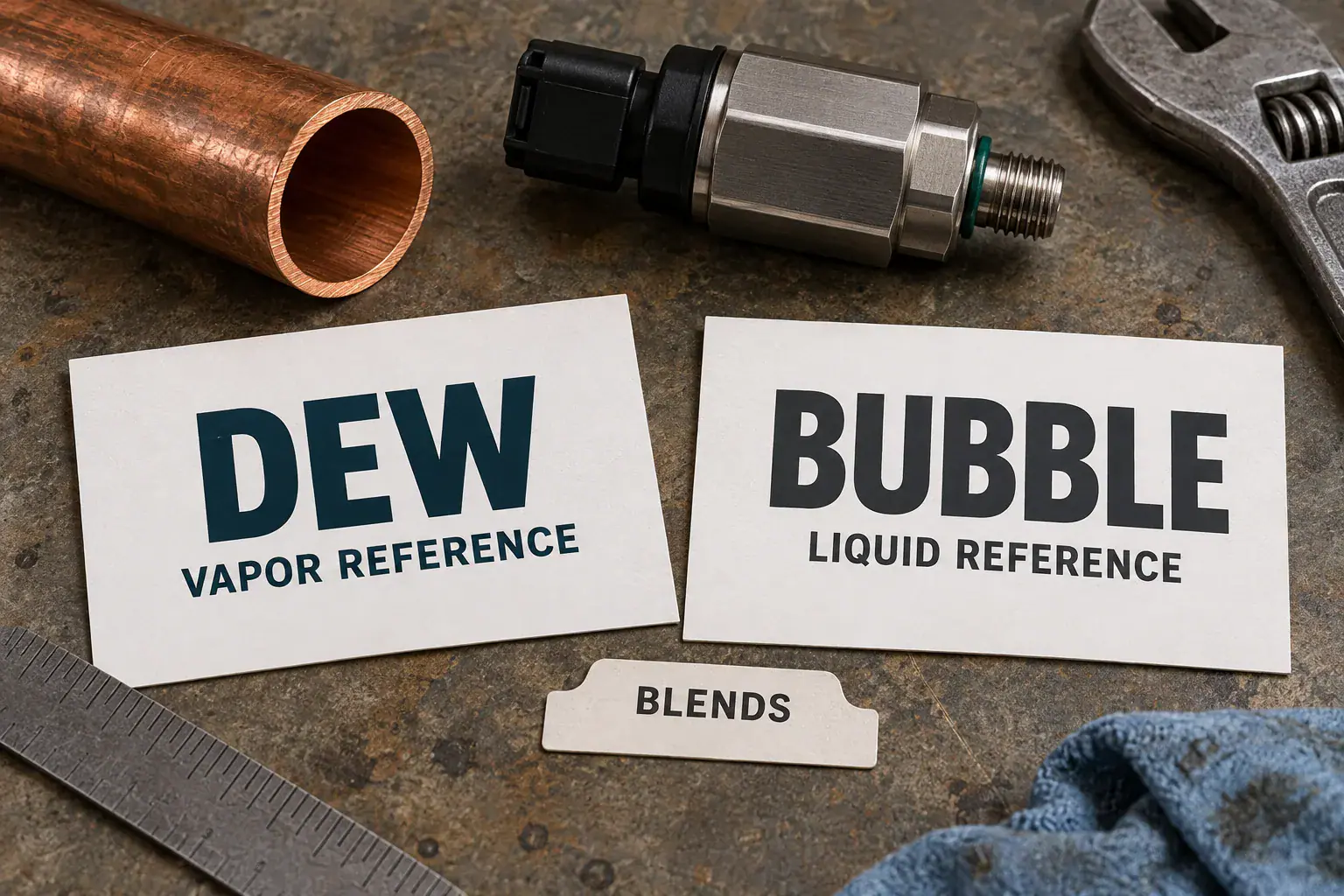
For example, suppose a hypothetical blend has a 2°C bubble value and a 6°C dew value at the measured outlet pressure. If the vapor pipe is 10°C, its superheat is 10 − 6 = 4 K. Using bubble instead would produce 8 K, an error of 4 K. This example illustrates reference selection; it is not a P-T table for a named refrigerant.
Record the refrigerant and whether pressure is gauge or absolute. A correct subtraction with the wrong refrigerant setting can still produce a plausible-looking answer. Preserve the instrument configuration or P-T reference with the test record so another engineer can reproduce the result.
What should normal superheat and subcooling be?
Targets depend on the equipment and its operating condition, including refrigerant, metering arrangement, load, measurement point and compressor requirements. Use the manufacturer’s operating and charging information for the exact model and test condition.
An evaporator control target and a compressor protection limit answer different questions. For example, Copeland’s RFT, RRT and RST compressor guidance specifies a minimum 20°F, or approximately 11 K, superheat at its stated compressor measurement point. That model-specific requirement is not a target for every evaporator outlet.
A fixed restrictor, a TXV, and an EEV also do not have identical responses to a load change. Some unitary equipment uses a manufacturer charging chart based on superheat or subcooling; other equipment requires a specified weighed charge or a different procedure. A generic internet range cannot replace that instruction.
If the original target is missing, request it before declaring the sample acceptable. Procurement should not turn an observed prototype value into a production limit without engineering approval.
Check the measurement before diagnosing a component
A temperature probe needs proper contact, suitable placement, and the insulation required by its instructions. Compare its reading with an independent instrument when a small difference would change the diagnosis. Inspect the pressure sensor’s range and whether its configured reference matches the installed device.

The Danfoss EKE 100 controller guide includes diagnostic entries for missing temperature-sensor configuration, pressure-transmitter signal faults and suction-pipe sensor wiring faults. Check those inputs before replacing a valve or changing coil geometry. Use the guide only for the controller models it covers.
Consider a hypothetical error budget. If a pipe-temperature reading may be wrong by ±0.5 K and the pressure-derived saturation temperature by ±0.7 K, a conservative sum of those two limits is ±1.2 K. That is not a formal uncertainty calculation, but it shows why a 0.5 K departure from a target cannot be judged without reviewing the instruments.
When a result is negative or near zero, verify the measurement and actual operating state promptly. A calculated negative superheat does not describe stable superheated vapor. It can reflect an unsuitable reference, a bad measurement, or a condition that needs investigation for liquid return.
What do high and low readings suggest?
“High” and “low” mean relative to the correct equipment target under comparable conditions. The following combinations are investigation paths for conventional DX equipment, not universal fault codes. Receiver-equipped systems, capacity control, multiple circuits, and transient operation can alter the pattern.
Paired observation
A reasonable next check
Evidence still needed
Paired observation: High superheat, low subcooling
A reasonable next check: Check whether the metering device receives adequate liquid
Evidence still needed: Correct local measurements, charge verification by the approved method, and leakage or liquid-feed evidence
Paired observation: High superheat, high subcooling
A reasonable next check: Investigate restricted or insufficient feed while liquid is available upstream
Evidence still needed: Pressure losses, filter-drier condition, valve/distributor suitability, and measurement locations
Paired observation: Low superheat, high subcooling
A reasonable next check: Check load, evaporator airflow and metering behavior before assuming overcharge
Evidence still needed: Stable load record, valve response, compressor-inlet condition, and the equipment’s charge procedure
Paired observation: Low superheat, low subcooling
A reasonable next check: Verify system state and measurement validity before assigning a cause
Evidence still needed: Startup/defrost status, refrigerant reference, load, controls and repeated readings
High superheat with low subcooling can be consistent with undercharge, but the pair alone does not establish it. High superheat with high subcooling can be consistent with a feed restriction, but only if the subcooling was measured at a meaningful upstream location and the system architecture supports that interpretation.
Copeland’s sight-glass guidance explains why bubbles can result from pressure loss when liquid is close to saturation, including losses at restrictions. It cautions against equating bubbles with low charge alone. A bubble is not an instruction to add refrigerant.
Write the next check into the report. For a possible feed restriction, identify the suspected component and the pressure measurements needed on each side. The technician can then test that explanation before replacing parts.
Why can condenser subcooling differ from valve-inlet subcooling?
Liquid can gain heat or lose pressure between the condenser and the metering device. Either change can reduce its local subcooling margin. A condenser-outlet value therefore does not prove the same margin remains after a long line, vertical lift, drier, or control device.
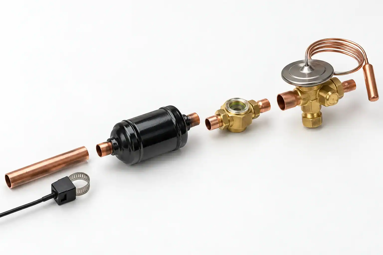
Copeland’s receiver design bulletin AE17-1212 describes liquid close to saturation in a partly filled receiver and the risk of flashing after pressure loss. Assess the margin at the point of interest using the corresponding local pressure and temperature, rather than carrying a condenser-outlet value through the entire system.
If a receiver or a separate subcooler is installed, show it on the measurement sketch. Follow the equipment’s charge and receiver-level procedure rather than treating condenser subcooling as a universal refrigerant-inventory indicator. Compare like locations when evaluating two suppliers’ test reports.
This distinction also changes the RFQ. Ask whether a quoted condenser duty includes a specified subcooling section and where the delivered liquid condition is defined. Do not assume that changing condenser area will correct a downstream piping problem.
Could airflow or frosting be causing the complaint?
A refrigeration coil depends on its air side as well as its refrigerant supply. Check the fan operation, return path, product loading, fin condition and frost state before deciding that the coil needs more capacity.

A blocked evaporator face changes the load transferred to the refrigerant. The resulting superheat response depends on the metering device and controls. A TXV may partly compensate, so an apparently acceptable superheat reading does not prove adequate airflow or useful cabinet capacity.
Likewise, investigate condenser airflow and inlet conditions when heat rejection is poor. Keep the observations separate: a dirty coil face is visible evidence; its measured effect on capacity requires operating data. The condenser coil guide covers the separate maintenance and construction questions.
For a replacement inquiry, provide photographs of the installed air path as well as the removed coil. A new coil that matches the old dimensions can inherit the same bypass gap or blocked return.
Record a stable operating condition
Readings taken during startup, pull-down, defrost recovery, fan cycling, or a capacity change should be labelled with that state. Do not compare them with a steady-operation target unless the manufacturer’s procedure calls for it.

For an OEM comparison, choose a defined test window and log the paired readings together with ambient temperature, cabinet or room condition, fan state, compressor state, and valve behavior where available. Use the equipment procedure to determine stabilization; a universal waiting time is not suitable for every system.
A steady average can hide a large swing. Preserve the range or time record when investigating hunting or intermittent low superheat. If the event occurs only after a door opening or defrost, retain that event in the test file rather than averaging it away.
Worked OEM example: check the probe before changing the coil
Suppose a development cabinet has a hypothetical approved test target of 6 ± 1 K evaporator-outlet superheat and 6 to 10 K valve-inlet subcooling at one defined operating point. These limits are invented for this example and must not be used as field targets.
The first record shows the earlier teaching values: 16°C outlet temperature, 4°C dew reference, and therefore 12 K superheat. Valve-inlet subcooling is 8 K. The team proposes a larger evaporator because the reported superheat is high.
The review sequence is:
- Confirm that the pressure and temperature refer to the same outlet location.
- Check the refrigerant and dew setting.
- Compare the contact probe with an independent measurement under the same operating state.
- Recheck the result after correcting the measurement installation.
Assume this investigation finds poor probe contact. In the hypothetical repeat test, the properly installed probe reads 10°C while the local dew reference remains 4°C. Calculated superheat is now 6 K, within the example’s approved band, with no coil modification.
The change from 12 K to 6 K corrected a measurement problem. It did not demonstrate an improvement in coil capacity. If the cabinet still misses its temperature requirement, investigate the remaining load, airflow, controls and system performance with that corrected record.
Build a coil review packet from the measurements
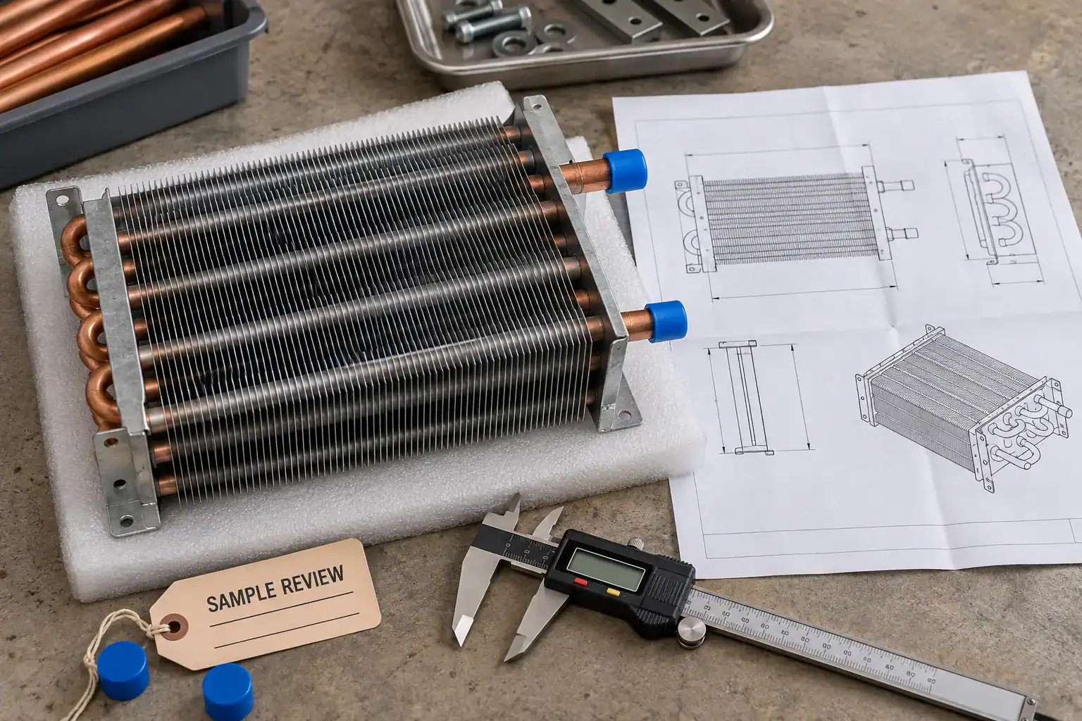
Once a component issue remains supported by the evidence, connect the operating record to the actual coil. Include the drawing revision so the supplier can relate the thermal complaint to the part being reviewed.
Include:
- Equipment model, intended application, refrigerant and metering arrangement.
- Measurement sketch, local pressures, pipe temperatures, P-T reference, calculated results and applicable targets.
- Operating state, ambient, load, fan duty, frost/defrost condition and controller trend where relevant.
- Coil drawing and revision, envelope, tube and fin arrangement, circuits, connections and mounting interfaces.
- Required cooling or heat-rejection duty, allowable pressure drops and the sample acceptance test.
- Sample quantity, estimated production quantity, destination and required inspection documents.
Identify what is measured, what is calculated, and what remains a target. If a larger face or different circuit is proposed, ask the supplier to state its effect on airflow, pressure drop, fit and the agreed rating point. The new design still needs the relevant equipment validation.
Frequently asked questions
What is the difference between superheat and subcooling?
Superheat measures how far vapor temperature is above its local saturation reference. Subcooling measures how far liquid temperature is below its local saturation reference. They use different parts of the refrigeration circuit and opposite subtraction orders. Both require the correct refrigerant and local pressure.
How do I calculate superheat from a pressure reading?
Convert the pressure to the refrigerant’s saturated-vapor temperature, using dew data for a blend. Subtract that value from the measured vapor-pipe temperature at the corresponding location. Pressure alone cannot provide superheat because the actual pipe temperature is also required.
Do I use dew or bubble for subcooling?
Use the saturated-liquid or bubble reference at the measured liquid pressure. Subtract the measured liquid-pipe temperature from that reference. Use dew for superheat. A mid-point value intended for performance ratings is not an automatic substitute for either calculation.
Does high superheat and low subcooling always mean low refrigerant charge?
No. It is an observation consistent with inadequate liquid supply in some systems, but it is not a unique diagnosis. Verify measurement quality, operating state, system architecture, liquid-feed conditions and the manufacturer’s charge-check procedure before deciding what action is justified.
Can high subcooling prove a liquid-line restriction?
No. Its meaning depends on the measurement location and system arrangement. Check the pressure losses and liquid condition around the suspected restriction, along with valve operation and charge information. A high value upstream does not describe the entire liquid line.
Is evaporator superheat the same as compressor superheat?
They are measured at different locations. Suction-line heat gain and pressure loss can change the saturation margin between the evaporator outlet and compressor inlet. Record the location and compare each value with the applicable evaporator-control or compressor requirement.
Can I use the same targets for R-410A, R-32 and R-454B?
Do not assume that you can. Use the exact refrigerant’s pressure-temperature data and the equipment maker’s operating requirements. Correct P-T conversion is only part of the check; targets also depend on the equipment model, measurement location and operating condition.
When do the readings justify replacing a coil?
When the remaining evidence supports a coil problem and the proposed replacement addresses it. Confirm measurement quality, airflow, refrigerant supply and controls first. Then compare the coil’s construction and rating with the required duty, and define a test that will verify the replacement.
Make the next decision from a reproducible record
Keep the local pressure, pipe temperature, refrigerant reference, operating state and target together. Recheck the measurement before deciding that a valve, condenser or evaporator is at fault. That record is useful to service, engineering and procurement because each team can see what the numbers establish and what still needs testing.
Request a coil review with the operating evidence
Domi’s custom coil fabrication service provides a route for reviewing drawings, samples and application requirements. For an evaporator or condenser project, send the coil revision and measurement record together. Identify whether you need a fit-compatible replacement, a new rating-point review, or a geometry proposal for an OEM program.
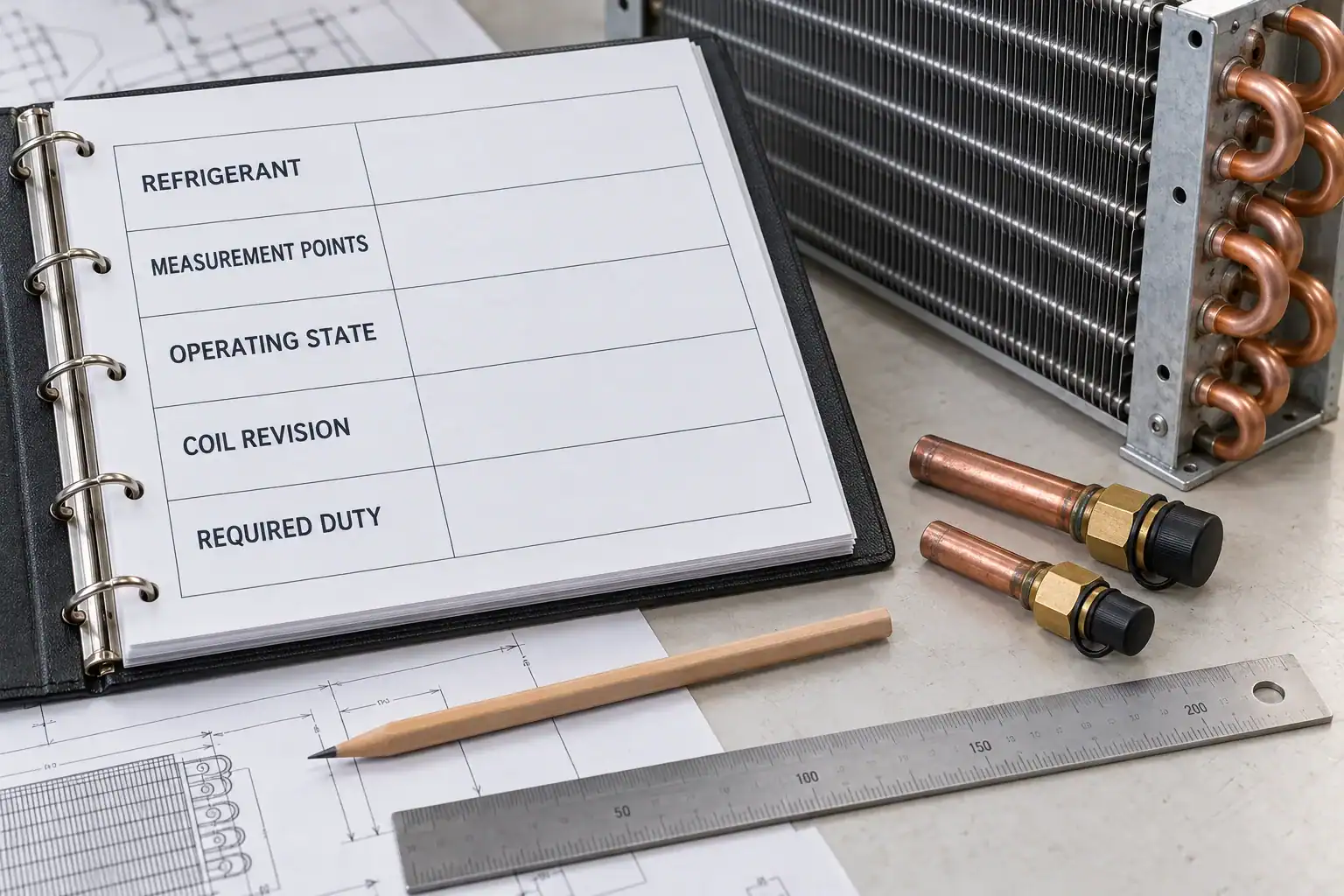
Include the required duty, available airflow, pressure-drop limits, refrigerant conditions and installation envelope. Domi can review the available information and identify inputs needed for a project discussion. Final construction, performance, inspection scope, sample timing and commercial terms require confirmation against the agreed specification.