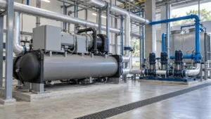
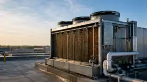
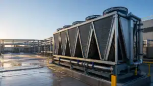
For most commercial foodservice walk-in coolers, start with a room setpoint near 37°F (2.8°C) and keep the product at or below the applicable food-safety limit. A practical operating band is usually 35°F to 38°F (1.7°C to 3.3°C), but the final setting depends on the product, door traffic, humidity, sensor location, coil TD, defrost method, and the local food code. Set the controller from measured product and return-air conditions, then size the evaporator for the real heat load rather than for room volume alone.
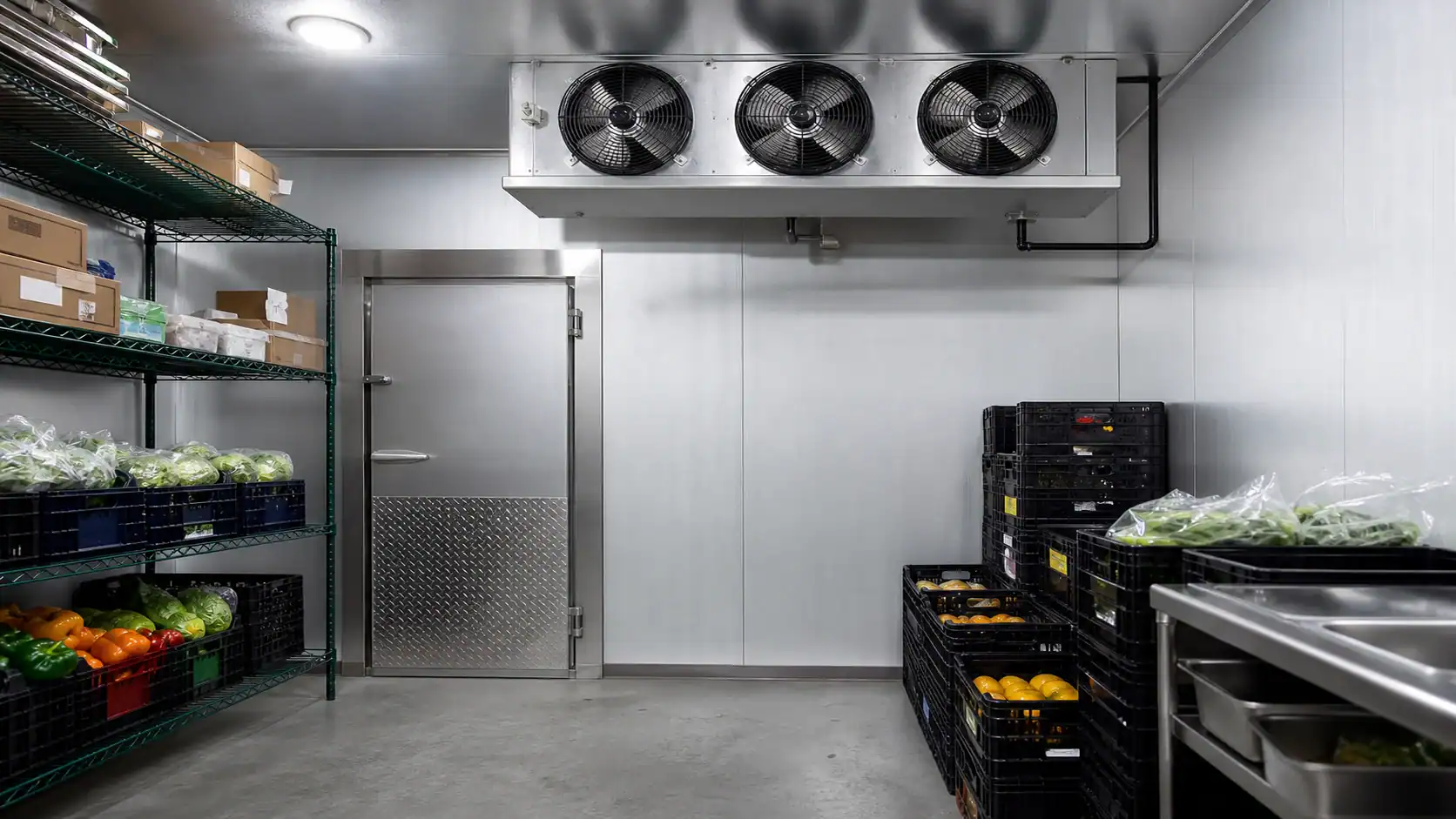
The phrase “walk-in cooler temperature” sounds simple because a number is easy to print on a controller. In a working room, that number is only one part of a thermal system. A room can display 37°F while product near the door is warmer, the coil is underfed, or an over-tight fin pack is slowly losing airflow to frost. The sections below connect the setpoint to the equipment and the information an OEM or coil supplier needs before releasing a quotation.
What temperature should a walk-in cooler be?
Use 35°F to 38°F as a screening range for a normal medium-temperature cooler, with 37°F as a useful target when products and the local code allow it. A controller should not be set right at a regulatory ceiling because door openings, loading, sensor error, and stratification create a small but important operating buffer. The product specification and the authority having jurisdiction still control the final value.
| Use case | Practical starting range | What to verify before release | Why the range changes |
|---|---|---|---|
| General produce, dairy, and beverages | 35°F to 38°F | Product tolerance, humidity, and return-air measurement | Protects chilled goods without intentionally freezing sensitive items |
| High-door-traffic foodservice room | 36°F to 38°F | Door schedule, infiltration load, and recovery time | A stable buffer helps absorb short warm-air events |
| Meat or seafood holding | 32°F to 36°F | Product specification, sanitation program, and local code | Product type and surface drying risk may call for a colder or tighter band |
| Produce with high moisture sensitivity | 36°F to 40°F | Relative humidity, air velocity, and coil TD | Excessive TD or airflow can increase dehydration |
| Beverage or packaged-goods room | 35°F to 38°F | Freeze protection and loading pattern | A low setpoint can damage cans, bottles, or sensitive liquids |
| Walk-in freezer, not a cooler | Below 0°F in many designs | Freezer design, defrost, and product requirement | The coil, fin spacing, insulation, and defrost architecture are different |
For food safety, do not treat a display reading as proof that every product is compliant. The U.S. Food and Drug Administration Food Code is a model, while the local inspector, product specification, and documented monitoring procedure determine what applies to a particular operation. Use calibrated probes and a written temperature log. If the room is used for a regulated product, have the responsible food-safety professional approve the setpoint and alarm limits.
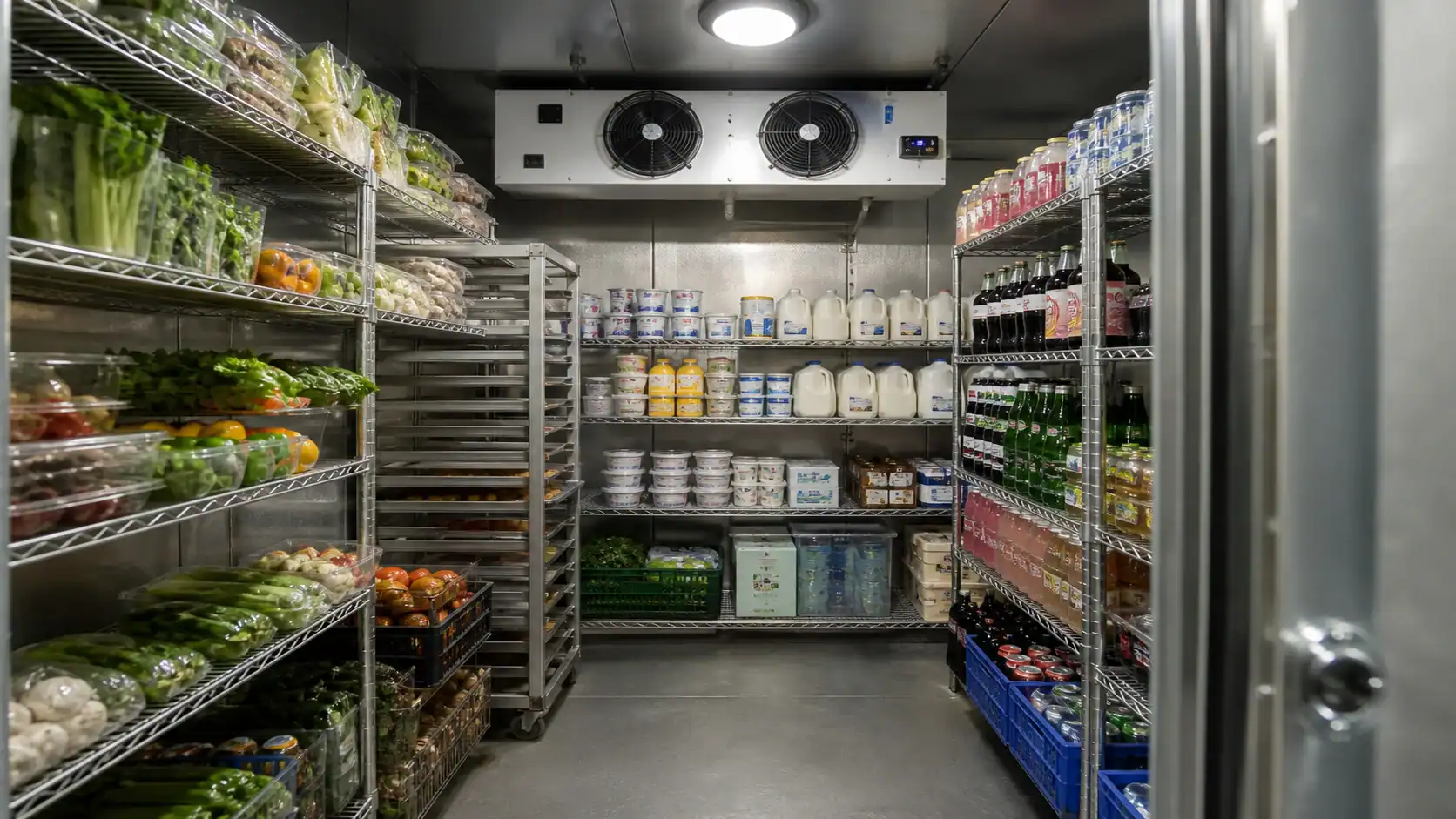
Setpoint, cut-out, and product temperature are different values
A refrigeration controller normally cycles between a cut-out temperature and a cut-in temperature. The difference is the control differential. For example, a controller that stops cooling at 36°F and restarts at 40°F has a 4°F differential. That may be reasonable for one product and too wide for another. A narrow differential can improve room uniformity but may increase starts, valve movement, and short-cycle risk if the sensor is poorly located.
Place the controlling sensor where it represents the room or return air, not directly in the discharge jet from the evaporator and not beside a warm door frame. Add a separate product probe when the product itself is the critical variable. The Danfoss walk-in cooler temperature-controls example shows why cut-out and differential settings must be considered together rather than as a single “correct” number.
Before changing a setpoint, record four readings at the same time:
- Controller display temperature.
- Independent return-air temperature.
- Product-core or product-surface temperature, as appropriate.
- Temperature near the door or the warmest rack position.
If the display is low but product is warm, look for sensor placement, stratification, airflow obstruction, excessive loading, or infiltration before adding capacity. If product is cold enough but the display swings widely, check the differential, sensor shielding, fan control, and compressor cycling. A temperature alarm should use a delay long enough to avoid nuisance trips during a normal door opening, while still catching a real loss of cooling.
Start with the room and heat load before choosing a coil
Walk-in cooler sizing is not a cubic-foot shortcut. A coil supplier needs the heat entering the room during the design event and the time allowed for recovery. The ASHRAE refrigerated-facility load guidance groups the work into transmission, product, infiltration, people, lighting, equipment, and related loads. It also cautions against adding every absolute peak as though all peaks occur at the same moment.
| Load source | Information to collect | Effect on the refrigeration package |
|---|---|---|
| Transmission | Panel construction, dimensions, floor, ceiling, ambient design temperature | Sets the continuous envelope load |
| Product pull-down | Product type, entering temperature, quantity per hour or day, target temperature, required time | Can dominate the peak capacity requirement |
| Door infiltration | Door size, openings per hour, open duration, strip curtains, humidity | Adds warm air and latent moisture that can become frost |
| People | Maximum occupants and time inside | Adds sensible heat and affects recovery |
| Lighting | Actual installed watts and operating schedule | Electrical input becomes room heat |
| Evaporator fans | Motor watts at the actual operating point | Fan energy becomes part of the room load |
| Other equipment | Motors, pumps, heaters, conveyors, and chargers | May run continuously or only during loading |
| Safety and diversity | Required margin, duty cycle, and whether loads overlap | Prevents both under-sizing and unnecessary oversizing |
Separate a holding load from a pull-down load. A room storing already chilled product may need modest capacity, while a room receiving warm product several times per day needs enough capacity to remove that product heat within the specified window. Send both the average and the peak case in an RFQ. If a quoted coil is based on an unexplained “required BTU/h,” ask for the calculation basis before comparing suppliers.
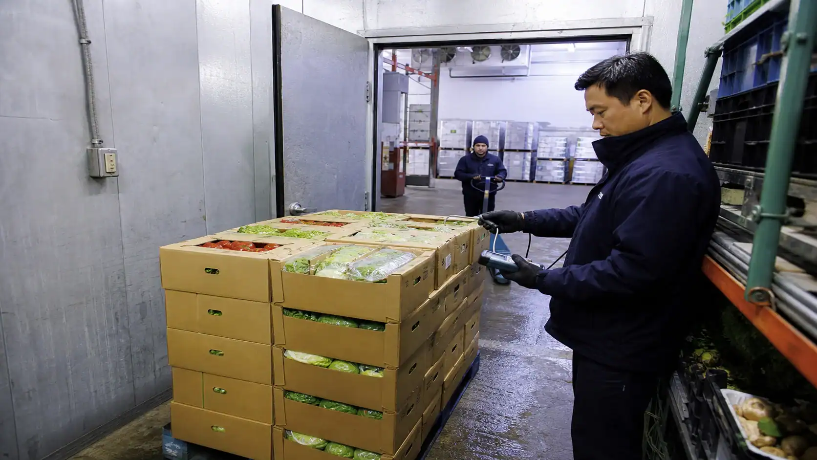
Match evaporator capacity to the actual operating condition
Do not compare two evaporators using only a catalog number such as “30,000 Btu/h.” Capacity changes with refrigerant, evaporating temperature, entering-air temperature, superheat, airflow, fan speed, and the rating convention. Ask the supplier to state net capacity at the design point and show the correction factors used.
The Danfoss cold-room component-selection guidance treats the evaporator, expansion device, condensing unit, refrigerant, and controls as a matched system. That is the right mental model for an OEM package: the coil should not be released independently from the valve, compressor or condensing unit, and control sequence.
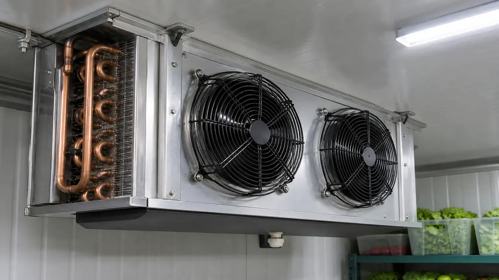
Use the following fields when a supplier returns a selection printout:
| Coil selection field | Minimum detail to request | Buyer decision it supports |
|---|---|---|
| Refrigerant and circuiting | Exact refrigerant, circuit count, design pressure, connection sizes | Confirms compatibility with the system architecture |
| Capacity point | Net Btu/h or kW, room temperature, evaporating temperature, superheat | Shows whether the coil meets the calculated load |
| Coil TD | Entering-air temperature minus saturated evaporating temperature | Reveals humidity, surface-temperature, and product-quality trade-offs |
| Airflow | CFM at operating condition, fan speed, external pressure | Predicts uniformity, air throw, noise, and fan heat |
| Geometry | Face area, rows, tube diameter, fin material, fin spacing | Helps compare pressure drop, frost tolerance, and service access |
| Fan data | Motor watts, voltage, phase, frequency, controls | Confirms electrical and heat-load assumptions |
| Defrost | Method, frequency, heater or hot-gas input, termination | Confirms recovery time and peak load |
| Drainage | Pan material, slope, outlet, trap, insulation, heater | Prevents standing water and refreezing at the outlet |
The coil TD deserves particular attention. A larger TD can reduce coil size, but it also lowers the coil surface temperature and can increase humidity removal, product dehydration, or frost formation. For produce and other moisture-sensitive loads, ask the supplier to show the design TD and the expected relative-humidity behavior instead of accepting a nominal rating.
Airflow, fin spacing, and frost determine temperature uniformity
Airflow should move enough air to mix the room and recover from loading without blasting product or creating a dead zone behind racks. Measure air throw toward the farthest storage position and check the return path. An oversized fan can increase noise, motor heat, and dehydration. An undersized fan can leave warm pockets while the sensor near the evaporator reports a satisfactory number.
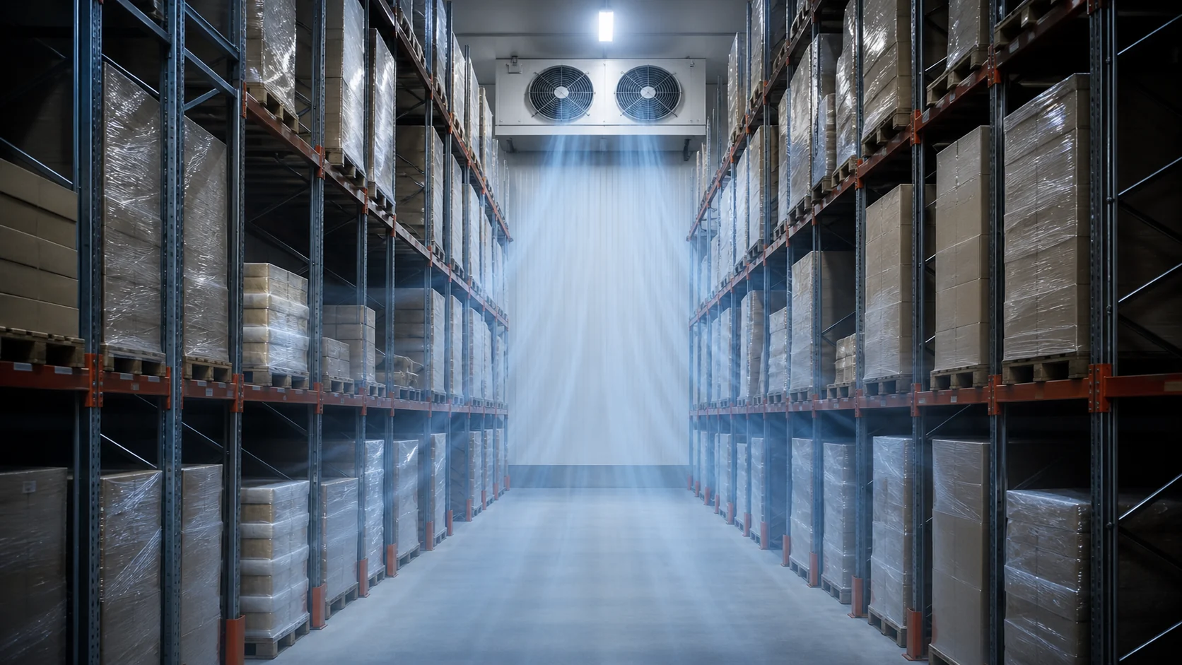
Fin spacing is a frost-management choice as much as a heat-transfer choice. Tighter spacing provides more surface area in a compact coil, but the passages close sooner when moisture freezes. Wider spacing tolerates frost and is easier to clean, though it may require more face area or rows for the same capacity. The ASHRAE forced-circulation air-cooler chapter is a useful technical reference; the final FPI should come from the application selection, not a universal rule.
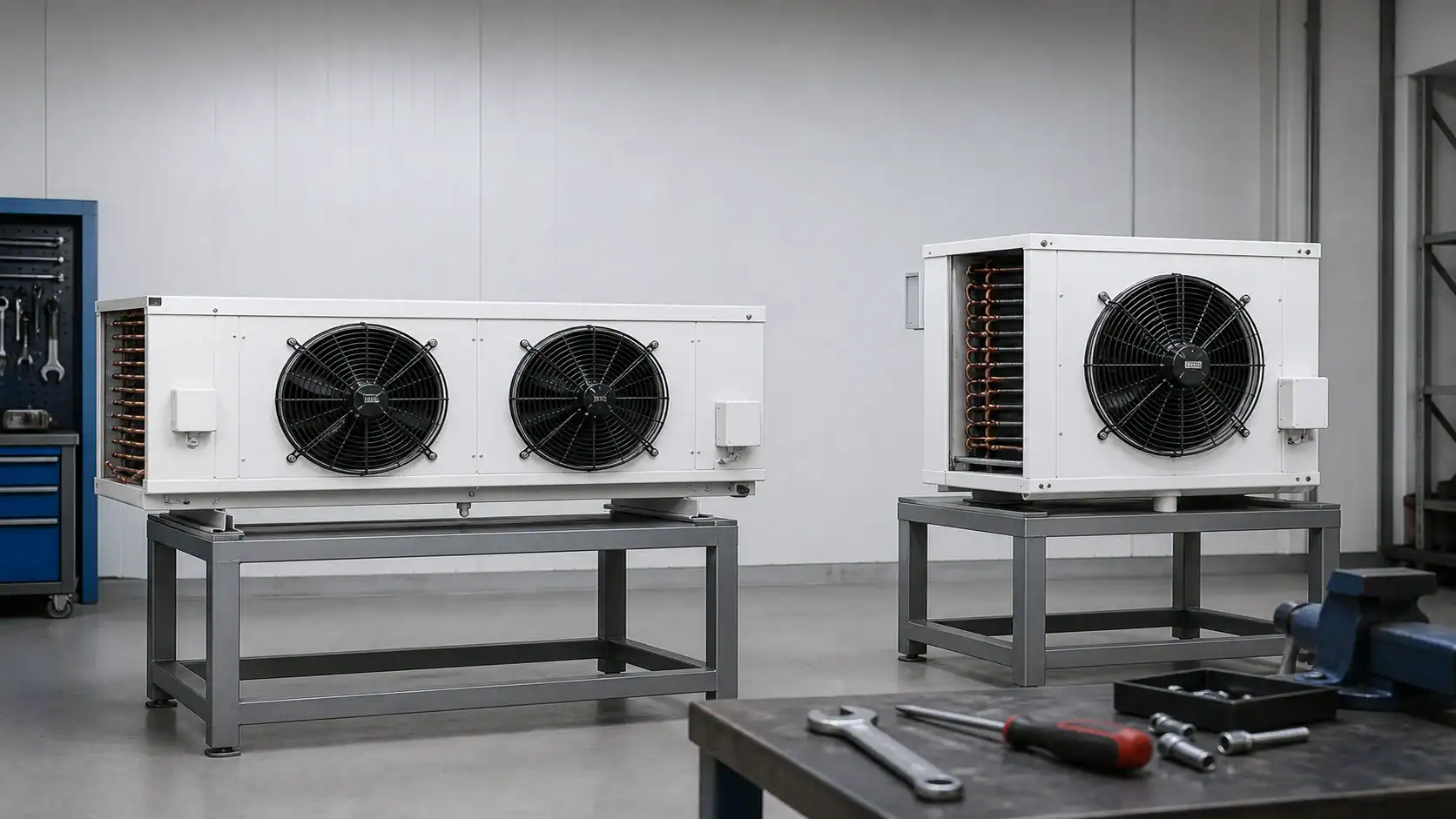
When a cooler serves mixed products, review the following points with the supplier:
- Keep the evaporator discharge clear of the door and leave the service clearance shown on the drawing.
- Keep racks below the intended air path; stacked cartons can create a short circuit between supply and return.
- Specify whether fans run continuously, cycle with the compressor, or use variable speed.
- Record fan motor watts at the operating voltage, since that energy becomes room heat.
- Confirm noise and air-velocity limits when people work inside the room.
- Test the warmest rack position, not only the controller sensor location.
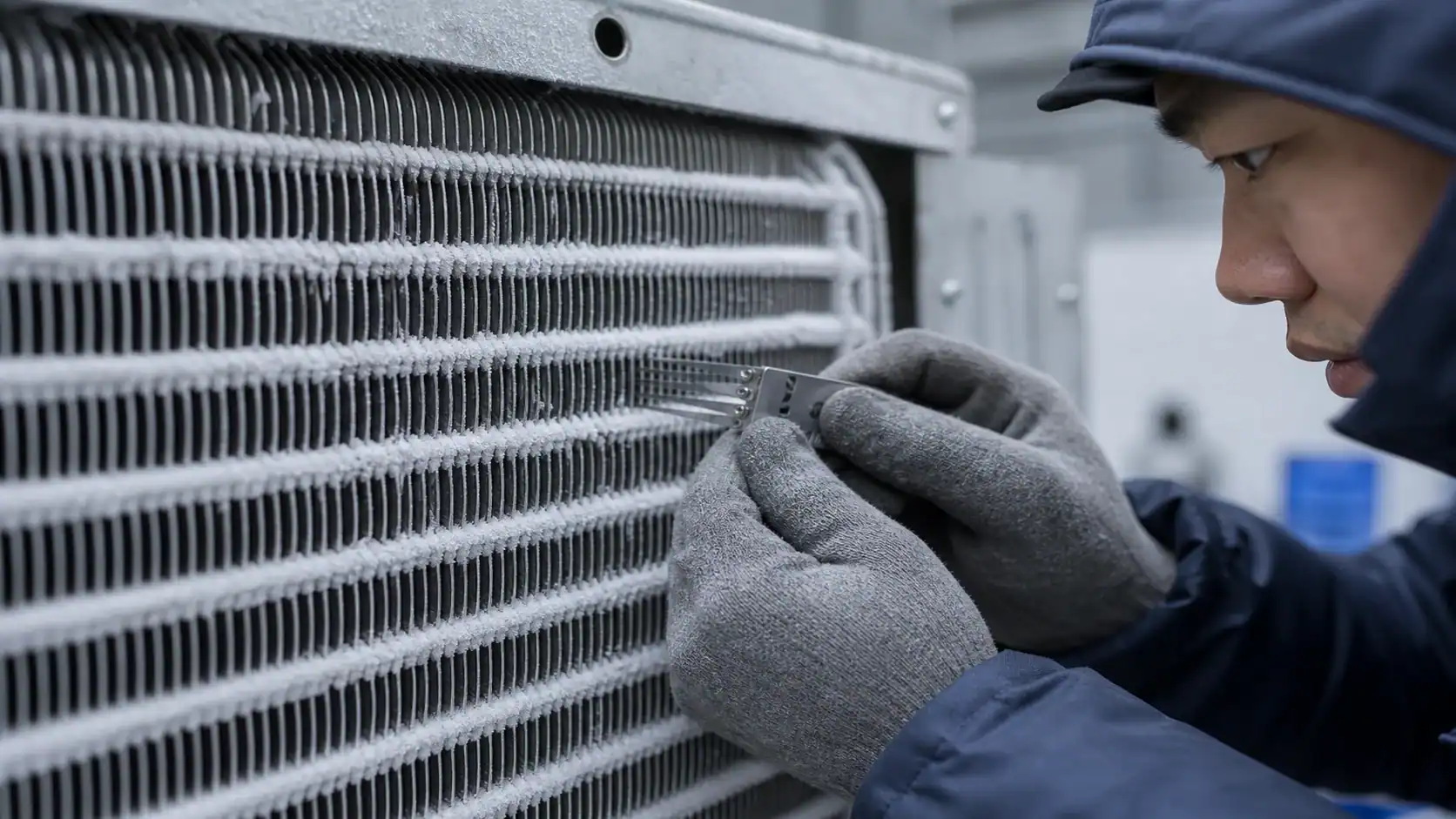
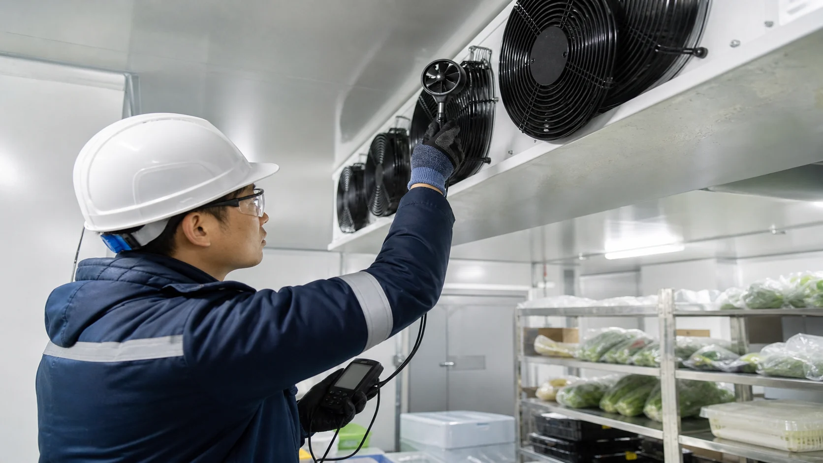
Defrost and condensate are part of the temperature design
A normal medium-temperature walk-in cooler may use off-cycle defrost when the coil can warm enough between cooling cycles. The controller still needs a fan restart and drip strategy so water does not blow onto product or refreeze at the drain. If the coil operates below freezing for long periods, electric or hot-gas defrost may be needed. The right choice depends on frost load, recovery time, electrical service, plant architecture, and maintenance capability.
The refrigeration defrost methods guide covers the sequence in more detail. For a walk-in cooler RFQ, state the expected door openings, humidity, defrost frequency, maximum room-temperature rise, termination method, and fan delay. “Defrost included” is not enough information to compare two bids.
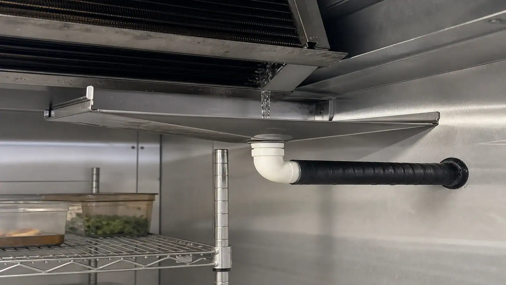
Use a separate drainage review for every installation:
- Show the pan slope and lowest outlet point on the drawing.
- Confirm the drain connection, trap requirement, and downstream route.
- Insulate the line where ambient moisture could condense or where the room can freeze it.
- Add a drain heater only when the lowest operating condition and defrost water require it.
- Keep fans off during the drip period and confirm that water has cleared before restart.
Refrigerant, materials, and mounting affect the final choice
The familiar commercial construction of copper tubes and aluminum fins is not automatically suitable for every application. Tell the coil manufacturer whether the system uses an HFC, HFO, A2L, CO₂, or ammonia refrigerant, and identify pressure, safety, and corrosion requirements. Ammonia systems, for example, require a different tube-material decision than a copper-tube commercial system. A washdown room, coastal site, or meat-processing plant may need a protective coating, stainless casing, or a different drain-pan material.
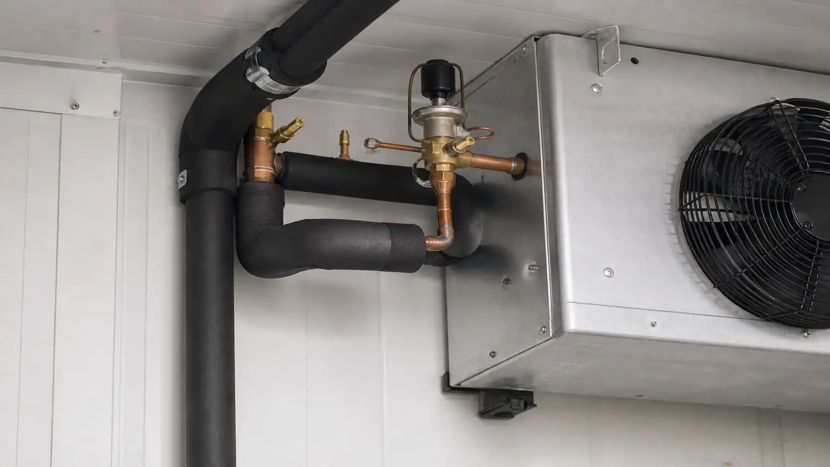
Also state the mounting envelope. A top-mounted unit, a low-profile ceiling unit, and a remote evaporator may share a capacity target but need different connection orientation, service access, fan clearances, and drain routing. Include maximum length, width, height, weight, lifting method, and the location of the electrical junction box. If a replacement coil must fit an existing housing, send a controlled drawing or a measured sample rather than relying on a model number.
OEM RFQ checklist for a walk-in cooler refrigeration package
An RFQ should make it possible for a second engineer to reproduce the selection. Attach a dimensioned room drawing, product schedule, and control sequence. The commercial refrigeration coil sizing guide can help organize capacity, face velocity, and pressure-drop inputs before you ask for a final quotation.

| RFQ block | Include | Evidence to request in the quotation |
|---|---|---|
| Room and product | L × W × H, insulation, floor, product, entering temperature, quantity, pull-down time | Load calculation with assumptions and diversity |
| Operating point | Room setpoint, allowable band, RH, ambient design, evaporating temperature, superheat | Net capacity at the stated point and correction factors |
| Air side | Airflow, air throw, fan count, fan watts, noise, rack layout | Fan curve, motor data, pressure drop, and service clearance |
| Coil construction | Tube, fin, casing, rows, face area, fin spacing, coating | Drawing, bill of materials, weight, and material confirmation |
| Defrost and drain | Method, cycles per day, termination, drip delay, pan, drain, heater | Control sequence, heater input, drain detail, and test condition |
| Refrigeration circuit | Refrigerant, circuiting, valve, condensing unit, controls | Matched component recommendation and operating envelope |
| Commercial terms | Prototype quantity, annual volume, MOQ, packaging, lead time | Scope exclusions, inspection records, and change-control process |
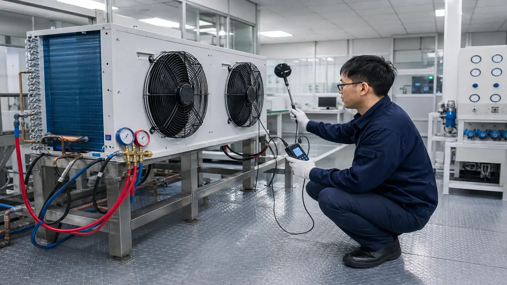
Ask the supplier to identify any value that is provisional. A quoted capacity based on a guessed product load, an assumed ambient, or a generic fan speed should be marked for confirmation before purchase. For a new platform, request one sample or a controlled pilot test that measures pull-down time, warmest-rack temperature, fan power, defrost recovery, and condensate drainage.
A practical troubleshooting path when the room will not hold temperature
When a walk-in cooler runs warm, change one variable at a time and record the result. The sequence below keeps a simple setpoint complaint from becoming an unnecessary compressor or coil replacement:
- Verify the controller with a calibrated reference probe at the same location.
- Compare return-air, discharge-air, product, and warmest-rack readings.
- Check that the door closes, gaskets seal, and strip curtains are intact.
- Confirm that racks and cartons do not block the evaporator discharge or return path.
- Inspect coil frost pattern, fan direction, fan speed, and actual motor current.
- Check refrigerant feed, superheat, liquid-line condition, and the expansion-device setting.
- Confirm that the defrost cycle terminates, drains, and restarts fans in the intended order.
- Recalculate the product and infiltration load if the loading schedule has changed.
Do not lower the setpoint as the first response to a warm product. A colder setpoint can increase coil frost, reduce humidity, lengthen recovery, or freeze a sensitive product while the real fault remains a door, airflow, sensor, or capacity problem.
Release-ready temperature specification
For a new walk-in cooler, put the thermal intent in the purchase specification: target room setpoint, allowable room band, product limit, sensor locations, alarm delay, design ambient, peak product load, coil TD, airflow, fin spacing, defrost, drain arrangement, refrigerant, and required test evidence. A clear specification lets the equipment supplier price the same job you intend to operate and gives your quality team objective acceptance criteria.
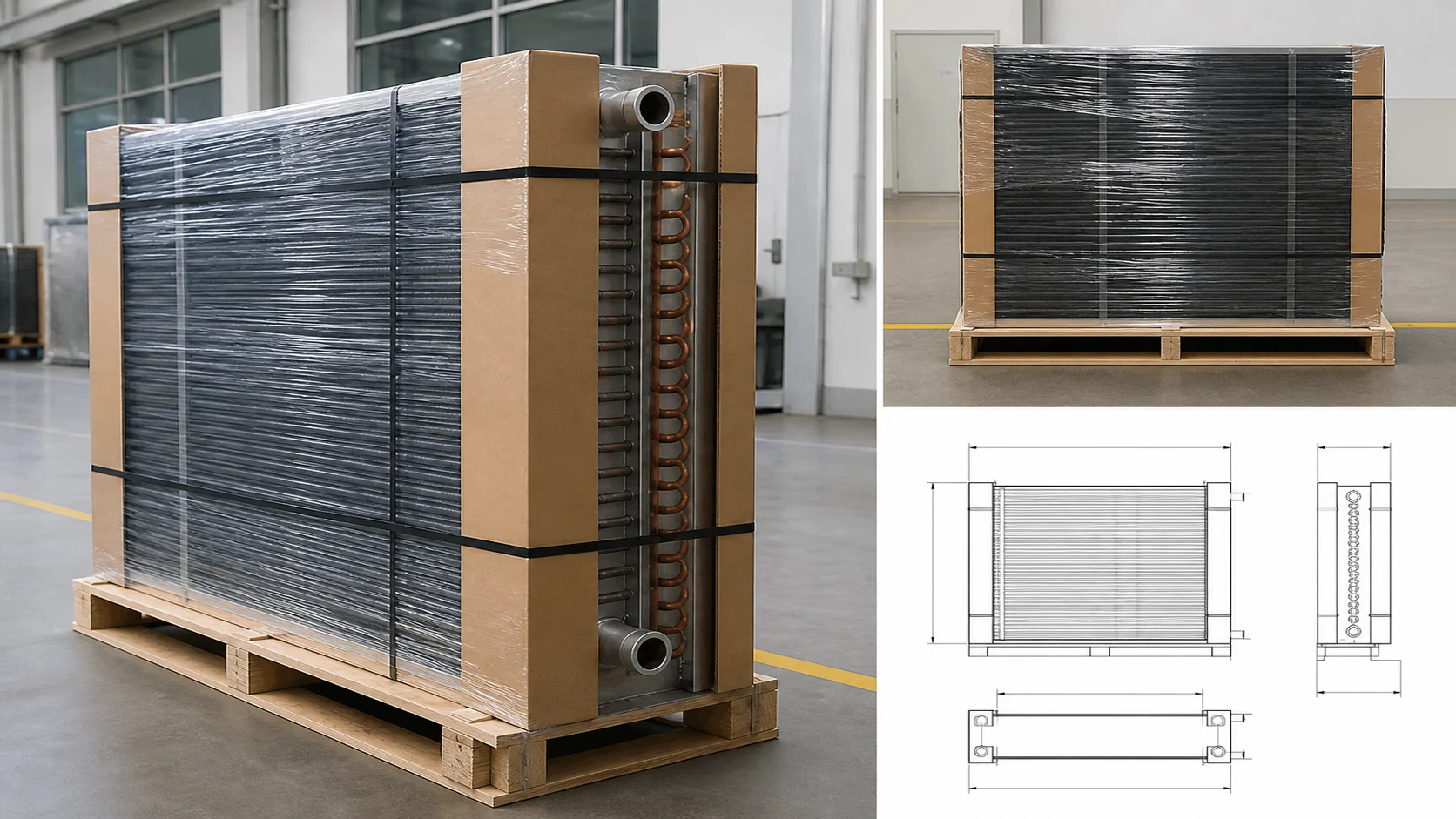
If you need a custom evaporator or commercial refrigeration coil, send the room drawing, product schedule, operating temperatures, refrigerant, airflow, fin-spacing preference, defrost method, and mounting limits to Domi’s commercial refrigeration coil team. The useful next step is a matched selection review, not a model number chosen from room volume alone.
Frequently asked questions
What is the best temperature for a walk-in cooler?
For many commercial foodservice rooms, 35°F to 38°F is a practical starting range and 37°F is a common target. The final value must follow the stored product, documented monitoring plan, local food code, door traffic, and humidity. Keep a buffer below any applicable maximum rather than operating at the limit.
Is 40°F too warm for a walk-in cooler?
It can be too warm for a product or process even when the controller shows 40°F. Check the product specification and the applicable food code, then measure the warmest product position with a calibrated probe. A room that briefly reaches 40°F during a door opening is different from a product that stays above its allowed limit.
Why is my walk-in cooler at the right setpoint but the product is warm?
Common causes are a sensor beside the evaporator, blocked airflow, poor door sealing, heavy warm-product loading, insufficient evaporator capacity, incorrect refrigerant feed, or an incomplete defrost cycle. Compare return-air, product, and warmest-rack readings before changing the setpoint.
How does evaporator coil selection affect walk-in cooler temperature?
The coil determines how much heat the system can remove at the specified refrigerant and air conditions. Capacity, coil TD, airflow, fin spacing, fan heat, defrost, and drainage all affect temperature uniformity and recovery. Request net capacity at the actual design point rather than comparing catalog capacity values from different conditions.
What fin spacing is suitable for a walk-in cooler evaporator?
The answer depends on room temperature, humidity, frost exposure, defrost interval, and allowable pressure drop. Tighter spacing can provide compact heat-transfer area in an above-freezing room, while wider spacing gives more frost tolerance. Let the manufacturer propose FPI against the load and test requirement, then record it on the drawing.
What should I send with a walk-in cooler refrigeration RFQ?
Send room dimensions and insulation, product and pull-down load, door schedule, ambient design, room and evaporating temperatures, refrigerant, capacity, airflow, fan power, fin spacing, coil geometry, defrost, drain arrangement, materials, mounting limits, controls, quantity, packaging, and required inspection or performance evidence. This allows suppliers to return comparable selections.