
For an OEM beverage cooler, R290 refrigerant changes more than the refrigerant name on the drawing. The condenser has to be selected as part of a charge-controlled, flammable-refrigerant system. The design team must close the cooling load, condensing temperature, cabinet airflow, internal refrigerant volume, circuiting, service access, and applicable product standard together.
The short answer is this: do not copy an R-134a or R-404A beverage cooler condenser and simply charge it with R-290. First define the target charge boundary and end use. Then size the airside and refrigerant-side geometry around the required heat rejection, pressure drop, compressor map, and safety construction. In the United States, the 2025 AIM Act transition dates concern certain products that use restricted HFCs; they do not, by themselves, mandate R-290. SNAP Rule 26 updated selected R-290 use conditions and aligned them with newer safety standards, but a 500 g value is not a universal beverage cooler allowance.
Jump to a section: The 150 g versus 500 g question · Design inputs · Coil geometry · OEM sequence · RFQ checklist · FAQs
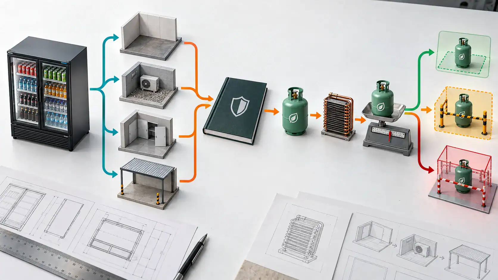
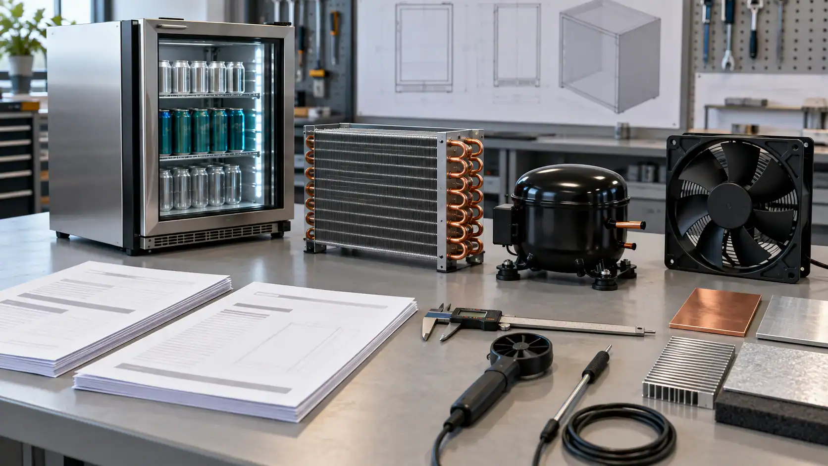
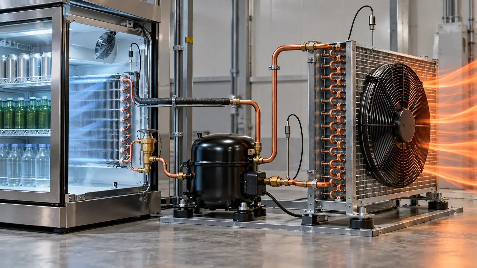
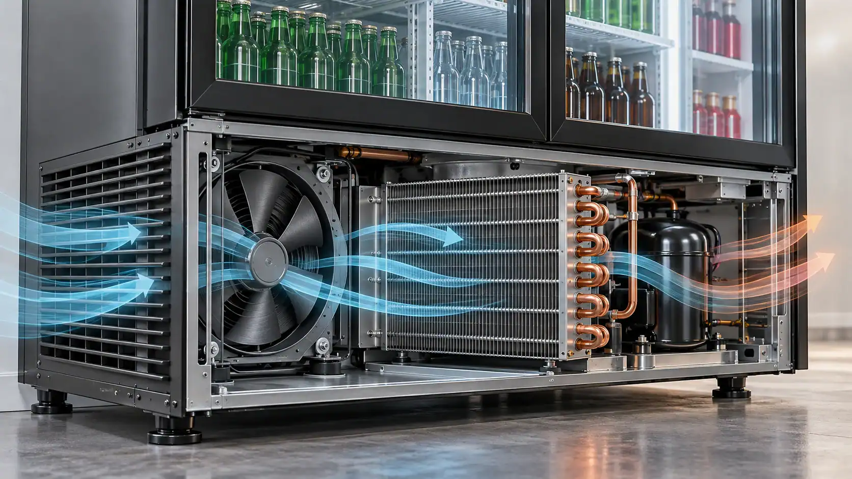
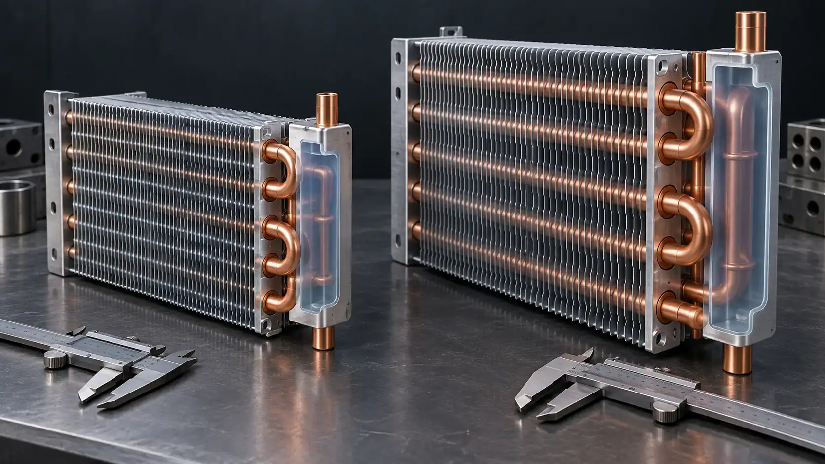
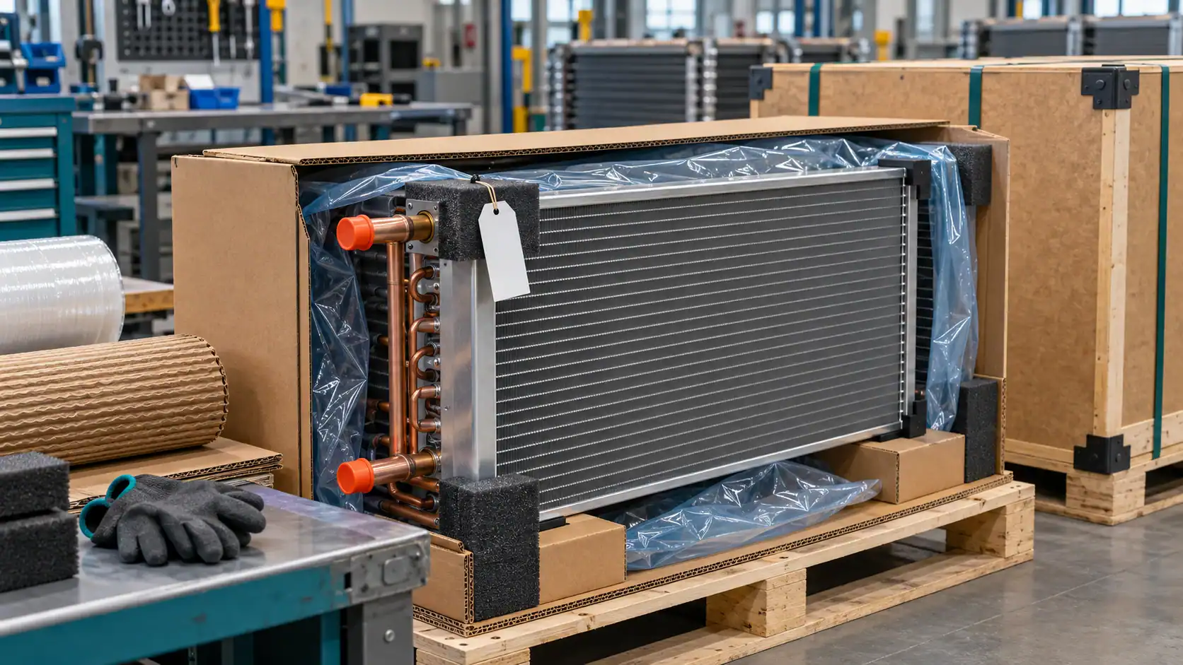
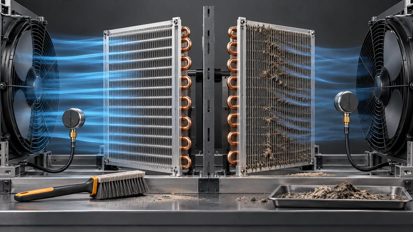
All visuals in this guide are AI-generated technical concept illustrations. They are not Domi product photographs, factory records, certification evidence, test results, or approved equipment designs.
R290 refrigerant properties that affect condenser design
R290 refrigerant is propane used as a single-component hydrocarbon refrigerant. Its low GWP can support a lower-impact refrigerant choice, but it does not set the allowable charge or approve a cabinet design. For an R290 condenser coil, the refrigerant identity, safety class, pressure-temperature behavior, inventory, and heat-rejection duty must be carried into the same design record.
Property
Verified reference
Condenser design implication
Designation and identity
R-290 is propane, formula CH3CH2CH3; see the ASHRAE refrigerant designation reference.
Use refrigerant-specific pressure-temperature data and the compressor manufacturer’s approved operating envelope when selecting the coil.
Safety classification
R-290 is listed as safety group A3 in the ASHRAE Handbook refrigerant table.
Separate leak, ignition-source, service, marking, and certification review from the thermal calculation; R-290 is not a drop-in replacement for R-134a.
GWP
EPA lists R-290 (propane) at GWP 3.3 on an IPCC 2007 basis in its GWP reference table.
Treat GWP as a refrigerant-selection and regulatory input, not as a charge allowance or safety approval.
Pressure and temperature behavior
Danfoss notes that R-290 pressure levels are closer to R-22/R-404A than to R-134a at comparable conditions in its hydrocarbon fitter notes.
Recheck tube working pressure, compressor map, condensing temperature, and pressure drop instead of copying R-134a assumptions.
Refrigerant-side inventory
Mass flow, density, liquid holdup, and component volume change with the operating point.
Recalculate tube size, circuiting, header layout, and the whole-loop charge budget at the stated design states.
Condenser sizing duty
Condenser heat rejection remains the evaporator load plus compressor input at the selected condition.
Balance face area, rows, fin pitch, fan airflow, condensing temperature, pressure drop, and charge budget together.
These references establish the design inputs; they do not replace the compressor data sheet, appliance standard, certification file, or test plan for a specific beverage cooler.
Is R-290 limited to 150 g or 500 g?
There is no single number that can be applied to every beverage cooler. The answer depends on the equipment category, whether the case is open or has doors or drawers, the safety standard used for certification, installation conditions, and the exact regulatory listing.
The most useful way to read the current U.S. position is to keep three layers separate:
- The AIM Act Technology Transitions program restricts the use of certain higher-GWP HFCs in named sectors and subsectors. EPA says restrictions for certain products and equipment began as early as January 1, 2025, but the applicable refrigerant, GWP limit, and date vary by subsector. Read the current EPA Technology Transitions Program and the sector restriction table.
- EPA SNAP listings are substitute and end-use specific. R-290 may be acceptable subject to use conditions for a named equipment type, but acceptance does not make an existing R-134a cabinet eligible for conversion.
- The product safety standard is a separate check. UL Solutions identifies R-290 as an A3 refrigerant and explains that commercial refrigeration appliances certified to UL 60335-2-89 can have higher charge limits in some configurations. The same article summarizes approximately 494 g for an open case and 304 g for an appliance with doors or drawers under the described multipliers. Those values are not a blanket approval for every cabinet, location, or certification route. See UL Solutions charge limits for A3 refrigerants.
SNAP Rule 26 became effective July 15, 2024. Its R-290 revisions moved selected use conditions toward UL 60335-2-89 and required equipment to be specifically designed and marked for the refrigerant. The Federal Register rule text is the right source for the exact end use. It is safer to treat the charge limit as a design input to verify than as a marketing number.
Freeze the design inputs before sizing the coil
The condenser cannot be sized from cabinet width alone. An OEM thermal engineer should freeze the following information before a coil supplier starts a geometry proposal:
- Refrigerant: R-290, including the intended refrigerant grade and the compressor manufacturer’s approved operating envelope.
- Refrigeration duty: target evaporating temperature, box temperature, pull-down requirement, design ambient, and steady-state heat load.
- Heat rejection: compressor power plus evaporator load at the selected operating point. A condenser should be checked at the actual worst-case heat rejection, not only at nominal catalog conditions.
- Airside boundary: available face area, fan model, airflow at installed resistance, inlet temperature, discharge path, and allowable sound or fan power.
- Charge boundary: the applicable standard and listing, maximum system charge, tubing volume, compressor shell volume, service access, and any installation restrictions.
- Cabinet geometry: condenser location, clearances, intake and discharge openings, adjacent electrical parts, and the distance from potential ignition sources.
- Manufacturing constraints: tube material, fin material, header or hairpin construction, braze or weld process, allowable tolerances, leak test method, packaging, and annual volume.
If any of these values are missing, the supplier can still review feasibility, but the output should be labeled as a concept or preliminary design. A drawing that does not state the design ambient, airflow, operating point, or charge target is not a complete condenser specification.
Use heat rejection as the first sizing check
The first-pass balance is simple: condenser heat rejection equals evaporator load plus compressor input at the selected condition. It is not a final rating method, but it prevents the common mistake of choosing a smaller condenser merely because R-290 has a different mass charge than an HFC system.
The final coil must then be checked for airside temperature rise, refrigerant condensing temperature, pressure drop, oil return, compressor discharge conditions, and control stability. A smaller charge target may reduce internal volume, but it does not remove the need to reject the same system heat at the required ambient.
How R-290 changes condenser coil geometry
R-290 design is a coupled problem. Charge reduction, heat-transfer area, pressure drop, circuiting, and service safety affect one another. The right geometry is the smallest design that meets the thermal and safety requirements with an auditable margin, not the smallest coil that physically fits.
Face area, rows, and fin pitch
Start with the airside because beverage coolers often have a tight fan and grille envelope. A compact coil with excessive fin density can create a pressure-drop problem, reduce installed airflow, and raise condensing temperature. A lower fin density may improve airflow but require more face area or more rows.
Review these choices together:
- Face area and frontal velocity at the real fan operating point.
- Number of rows and tube length within the available cabinet depth.
- Fin pitch that can tolerate the expected dust and cleaning interval.
- Air bypass around the frame, headers, and fan shroud.
- Clearance for cleaning and for separation from electrical or ignition-risk components.
Tube diameter and refrigerant-side volume
Tube diameter and circuit length determine both refrigerant-side pressure drop and internal volume. A larger tube can reduce pressure drop but may add charge volume. A smaller tube can reduce internal volume but may increase pressure drop and make fabrication or cleaning more demanding.
For R-290, the decision should include:
- Total internal volume of tubes, headers, bends, and connecting lines.
- Pressure drop at the expected vapor and liquid conditions.
- Liquid holdup during start-up, shut-down, and transient operation.
- The effect of circuit length on condensing temperature and oil movement.
- The effect of header placement on distribution and service accessibility.
Do not optimize the coil in isolation from the rest of the system. The charge calculation must include the evaporator, suction and liquid lines, compressor volume, filter drier, and any other refrigerant-containing component.
Circuiting and header layout
Circuiting is often where a copied HFC coil fails. R-290 mass flow, pressure drop, and compressor operating conditions may require a different number of circuits or a different pass arrangement. A circuit that is too long can add pressure drop and refrigerant volume. Too many short circuits can complicate distribution, brazing, and repeatability.
Ask the coil designer to show the circuiting, not only the outside dimensions. The drawing should identify tube size, number of circuits, inlet and outlet locations, flow direction, header construction, and any internal volume estimate used in the charge budget.
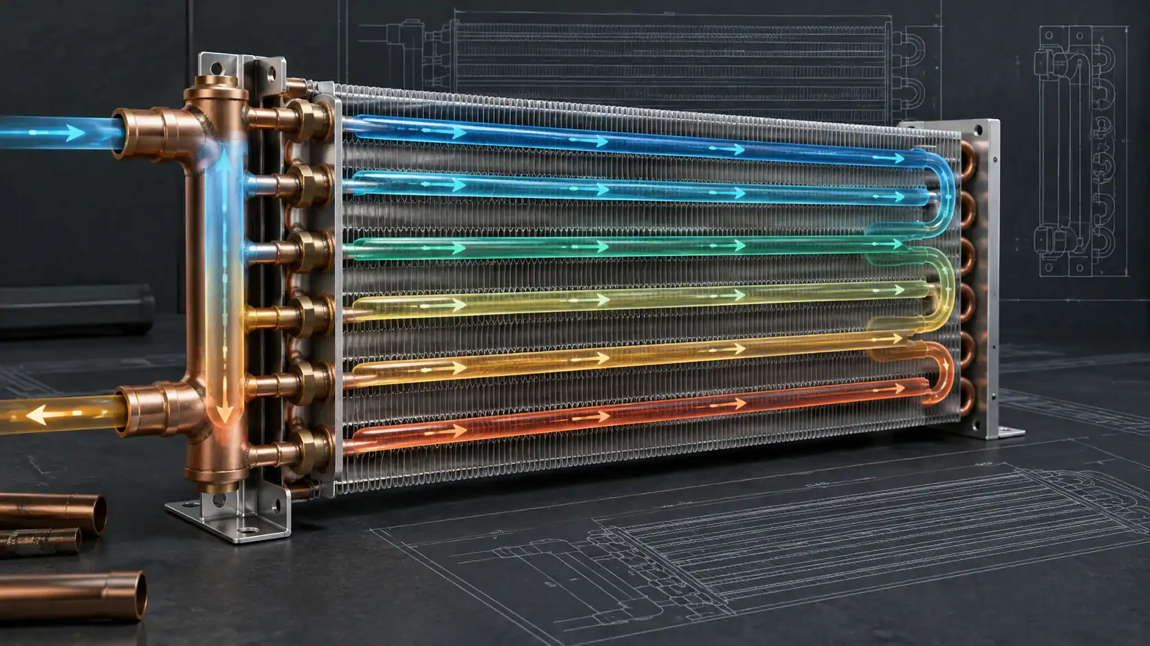
Design variables that shift charge and thermal performance
The following decision grid is useful when an OEM must reduce charge without losing the required heat rejection. It is a screening tool, not a substitute for a component-level charge calculation or a tested coil rating.
Design Variable
Effect on Charge
Thermal Trade-off
OEM Verification
Internal tube and header volume
Larger internal volume increases refrigerant inventory; shorter or smaller passages reduce it.
Reducing volume can raise pressure drop or limit available heat-transfer surface.
Calculate volume by component and operating state; check pressure drop and joining limits.
Face area and row count
More tube length and rows can add internal volume.
More area can lower condensing temperature, while extra depth or rows can increase airflow resistance.
Check the installed fan curve, face velocity, cabinet depth, and condensing temperature.
Tube diameter
Larger diameter increases internal volume; smaller diameter reduces it.
Larger tube can reduce pressure drop; smaller tube can increase pressure drop and fabrication sensitivity.
Verify tube volume, refrigerant-side pressure drop, material, and repeatable joining.
Fin pitch
Fin pitch has little direct effect on charge compared with tube and header volume.
Dense fins can increase airflow resistance and fouling risk; open fins may require more area or rows.
Check airflow, static pressure, cleaning interval, bypass, and installed heat rejection.
Circuiting and header layout
Circuit length and header volume change the refrigerant inventory.
Shorter circuits may reduce pressure drop and volume, but distribution and joining can become harder to control.
Review the circuit drawing, flow direction, header volume, leak test, and oil movement.
Heat-rejection target
A higher duty does not lower charge; it may require more surface or airflow.
More capacity can require additional area, rows, fan power, or a higher condensing temperature.
Confirm evaporator load plus compressor input at design ambient and the actual fan condition.
What the charge limit means for the whole refrigeration loop
The charge ceiling is a system constraint, not a condenser-only constraint. When the target charge is tight, the design team should make the refrigerant inventory visible by component and by operating state.
An early charge budget can track:
- Condenser tube and header volume.
- Evaporator tube and header volume.
- Suction and liquid line volume.
- Compressor internal volume and oil separator volume if present.
- Filter drier, service valve, accumulator, and other components.
- Liquid migration during off-cycle and the operating state used for the estimate.
Reducing condenser volume can help, but a very small condenser may increase condensing temperature and compressor work. Shorter lines can reduce charge but may require a different cabinet arrangement. A compact evaporator, reduced receiver volume, or a different control strategy may be more effective than forcing all of the reduction into the condenser.
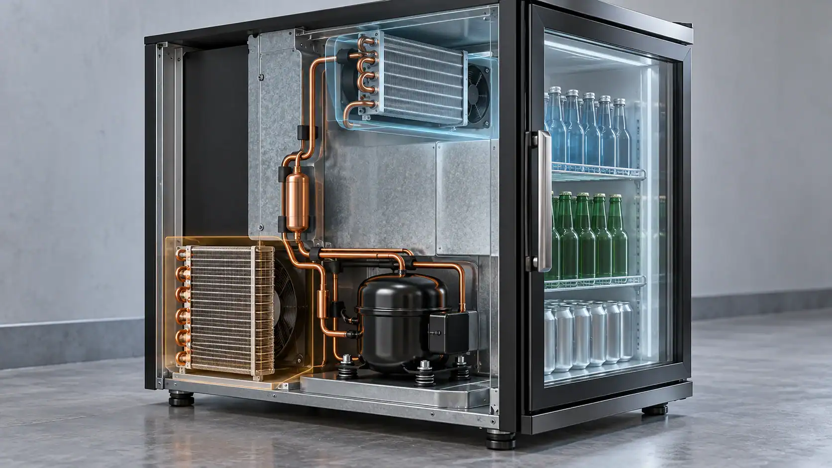
R134a-to-R290 design recalculation checklist
R290 is not a drop-in replacement for R134a. A change of refrigerant requires a new refrigeration system design review because compressor compatibility, pressure-temperature behavior, mass flow, internal volume, controls, flammability interfaces, and certification assumptions are coupled. Use the checklist below before releasing a revised condenser drawing.
- Compressor compatibility: confirm the approved R-290 compressor model, oil, starting behavior, operating envelope, discharge temperature, and controls.
- Capacity and mass flow: recalculate capacity, mass flow, compressor input, heat rejection, and the design ambient point; do not transfer an R-134a catalog rating by nameplate alone.
- Condenser volume and charge: measure tube, header, bends, line, evaporator, compressor, and accessory volumes in the whole-loop budget.
- Pressure drop and circuiting: recalculate tube diameter, circuit length, headers, liquid holdup, pressure drop, condensing temperature, and oil movement.
- Airside and thermal performance: recheck face area, rows, fin pitch, fan curve, cabinet bypass, sound, and the installed heat-rejection requirement.
- Safety and certification: review electrical separation, leak paths, service procedure, markings, test conditions, and the applicable standard for the target market.
The correct output is a new verified design record, not a relabeled R-134a drawing. The Danfoss R290 fitter notes are useful for understanding why pressure and compressor assumptions need to be revisited; the final selection still depends on the approved component data for the appliance.
Safety details that must stay in the mechanical design
R-290 is a highly flammable A3 refrigerant. A coil drawing cannot prove system safety, but it should not create avoidable hazards. EPA’s SNAP Rule 26 use conditions and UL 60335-2-89 requirements address equipment design, testing, charge sizes, ventilation, usage space, and markings for the relevant end use.
For a beverage cooler condenser, review at least these interfaces:
- Keep joints, service ports, and potential leak paths away from electrical components that can be ignition sources under normal or abnormal operation.
- Define how the fan, wiring, controls, compressor compartment, and airflow path interact after a leak scenario.
- Keep red markings, warning labels, and refrigerant identification consistent with the applicable product standard and certification file.
- Do not treat a low-GWP refrigerant as a retrofit fluid for a cabinet designed for another refrigerant.
- Make the service procedure, leak detection method, evacuation method, charging method, and recovery instructions consistent with the equipment design.
The correct installation distance, occupancy restriction, ventilation requirement, and charge multiplier must come from the applicable certification route and local code. They should not be guessed from a generic R-290 chart.
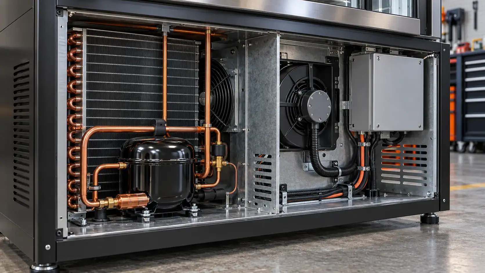
A practical OEM design sequence
Use this sequence when moving from an HFC beverage cooler concept to an R-290 condenser proposal:
- Classify the product and market. Identify whether it is a self-contained beverage cooler, open case, refrigerated vending appliance, or another category. Record the destination market and the certification route.
- Confirm the charge boundary. Determine whether the design must stay near 150 g or can use a higher charge under the exact product standard and installation conditions. Do not copy the 494 g or 304 g examples without checking applicability.
- Freeze the thermal point. Record evaporating temperature, condensing temperature, ambient, compressor input, cooling load, fan airflow, and allowable pressure drop.
- Build a volume budget. Estimate internal volume for every refrigerant-containing component, then identify which component has the greatest reduction potential.
- Select geometry and circuiting. Compare face area, row count, fin pitch, tube size, circuit length, and header arrangement against heat rejection and charge targets.
- Model the installed system. Use the real fan curve, cabinet openings, compressor map, line lengths, and controls. A free-air coil rating is not the same as an installed beverage cooler rating.
- Prototype and test. Check leak tightness, airflow, condensing temperature, capacity, power, sound, start-up, shut-down, and temperature recovery at the intended ambient range.
- Freeze the certification package. Keep the coil drawing, material specification, joining process, pressure or leak test record, charge calculation, and final appliance safety review aligned.

R-290 condenser coil RFQ checklist
Send the following with the drawing or request for quote so a coil supplier can respond with a usable proposal:
- Refrigerant and safety classification: R-290, A3.
- Target heat rejection and the condition at which it is required.
- Evaporating temperature, condensing temperature or ambient, and compressor model.
- Cabinet envelope: length, height, depth, mounting points, service clearances, and airflow direction.
- Fan model or airflow and static pressure at the installed condition.
- Tube material, tube diameter, fin material, fin pitch, coating requirement, and header preference.
- Number of circuits or the required pressure-drop limit, if already defined.
- Maximum refrigerant charge and the standard or certification basis used to set it.
- Connection size and location, brazing or joining requirements, leak test pressure, and cleanliness requirement.
- Prototype quantity, sample timing, production quantity, packaging, and delivery destination.
If the geometry is not fixed, send the appliance load and envelope first and ask for a design review. Domi’s custom coil fabrication service and engineering capabilities are the relevant starting points for a drawing-led review. For a prototype or production inquiry, use testing capabilities and contact to state the required operating point and documentation.
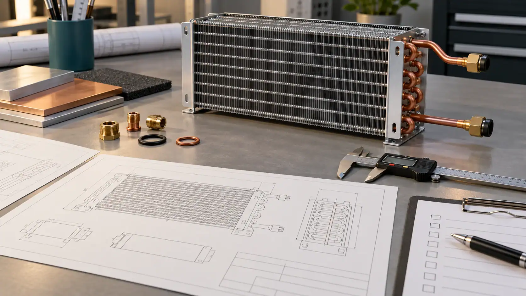
Common design mistakes
Treating 500 g as a universal design target
The higher-charge examples associated with UL 60335-2-89 apply only to the described appliance configurations and their installation restrictions. Using 500 g as a universal beverage cooler target can invalidate the certification assumption and distort the coil volume budget.
Choosing the coil from nominal capacity only
Two coils with the same nominal heat rejection can have different pressure drops, fan power, internal volume, and transient behavior. Compare the installed operating point and the charge budget, not only a catalog capacity.
Reusing the old HFC circuiting
R-290 may require a different circuit length, tube size, control setting, and compressor match. Reusing an HFC coil drawing without recalculating pressure drop and internal volume is a design shortcut, not a validated conversion.
Hiding the certification assumptions
Put the intended refrigerant, charge limit, installation category, standard, and test conditions on the engineering record. If those inputs are unknown, label the drawing preliminary and resolve them before production release.
Related refrigeration resources
Frequently asked questions
What is R-290 refrigerant?
R-290 is propane used as a refrigerant. It is classified as an A3 refrigerant, so flammability, charge size, equipment construction, installation, service, and marking requirements must be reviewed together.
Does the AIM Act require every beverage cooler to switch to R-290?
No. The AIM Act Technology Transitions Program restricts certain HFC uses in named sectors and subsectors. It does not create a universal rule that every beverage cooler must use R-290. The exact restriction, GWP limit, and compliance date depend on the product category and market.
Is the R-290 beverage cooler limit 150 g or 500 g?
Neither number is universal. A 150 g limit appears in many general A3 charge discussions, while UL 60335-2-89 commercial refrigeration configurations can allow higher charges under specific conditions. The correct value must be confirmed for the appliance, enclosure, installation location, certification route, and applicable code.
Can I use 494 g of R-290 in any open beverage cooler?
No. The approximate 494 g example is tied to the open-case multiplier summarized by UL Solutions for applicable commercial refrigeration appliances. It does not replace the appliance standard, listing, installation instructions, or local code review.
How does R-290 affect condenser sizing?
R-290 affects the system’s mass flow, pressure drop, internal volume, compressor match, controls, and safety construction. The condenser still has to reject the required heat at the design ambient. A lower charge target does not automatically mean a lower heat-rejection requirement.
Can I reuse an R-134a beverage cooler condenser?
Do not assume that you can. Reuse requires a new evaluation of heat transfer, pressure drop, charge volume, compressor compatibility, controls, joints, electrical separation, certification, and service procedure. In many cases, a new coil and system review is the safer engineering path.
What should an OEM send for an R-290 condenser quote?
Send the refrigerant, heat rejection, operating temperatures, compressor model, cabinet envelope, fan data, connections, material and finish requirements, maximum charge, intended standard, prototype quantity, production volume, and required test documentation.
Can Domi review a beverage cooler condenser drawing?
Yes. Send the drawing, target operating point, charge boundary, airflow data, and required documentation through Domi’s engineering capabilities or contact page. The review should begin with the system requirements rather than only the coil outline.
Need an R290 beverage cooler condenser design review?
Share the condenser drawing, target charge, heat rejection, cabinet envelope, airflow, compressor model, and certification market so the R290 condenser design can be reviewed against the complete refrigeration system rather than the coil outline alone.
Send the drawing with the target charge, heat rejection, cabinet envelope, airflow, and certification market.