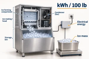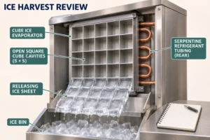

A heat recovery system is worth specifying when a refrigeration plant rejects useful heat at the same time another process needs hot water, space heating or wash water. Start with the temperature and timing of that heat demand, then match the refrigeration duty, recovery route, heat exchanger, storage, controls and safety boundary. A recovery package that raises condensing pressure without a dependable heat sink can consume more power than it saves.
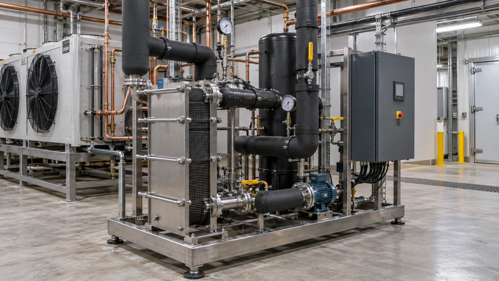
Start with the heat sink, not the heat exchanger
The first question is not “which heat recovery unit should we buy?” It is “where will useful heat go during normal refrigeration operation?” Write down the heating load, required supply temperature, return temperature, flow, operating hours and acceptable temperature variation. Then compare that demand with the refrigeration system’s heat-rejection profile.
This heat-sink-first check separates a useful project from a decorative energy feature. A cold store may have a steady refrigeration load but only occasional wash-water demand. A food plant may need hot water every shift but operate the refrigeration rack at a low load overnight. A buffer tank, staged recovery or a bypass to the original condenser may be needed when the two schedules do not align.
The ASHRAE Handbook is a useful reference for the system boundary, but it does not replace a project heat balance, pressure review or refrigerant safety assessment. The supplier should state which heat is recovered, at which operating point, and what happens when the heat sink is full or unavailable.
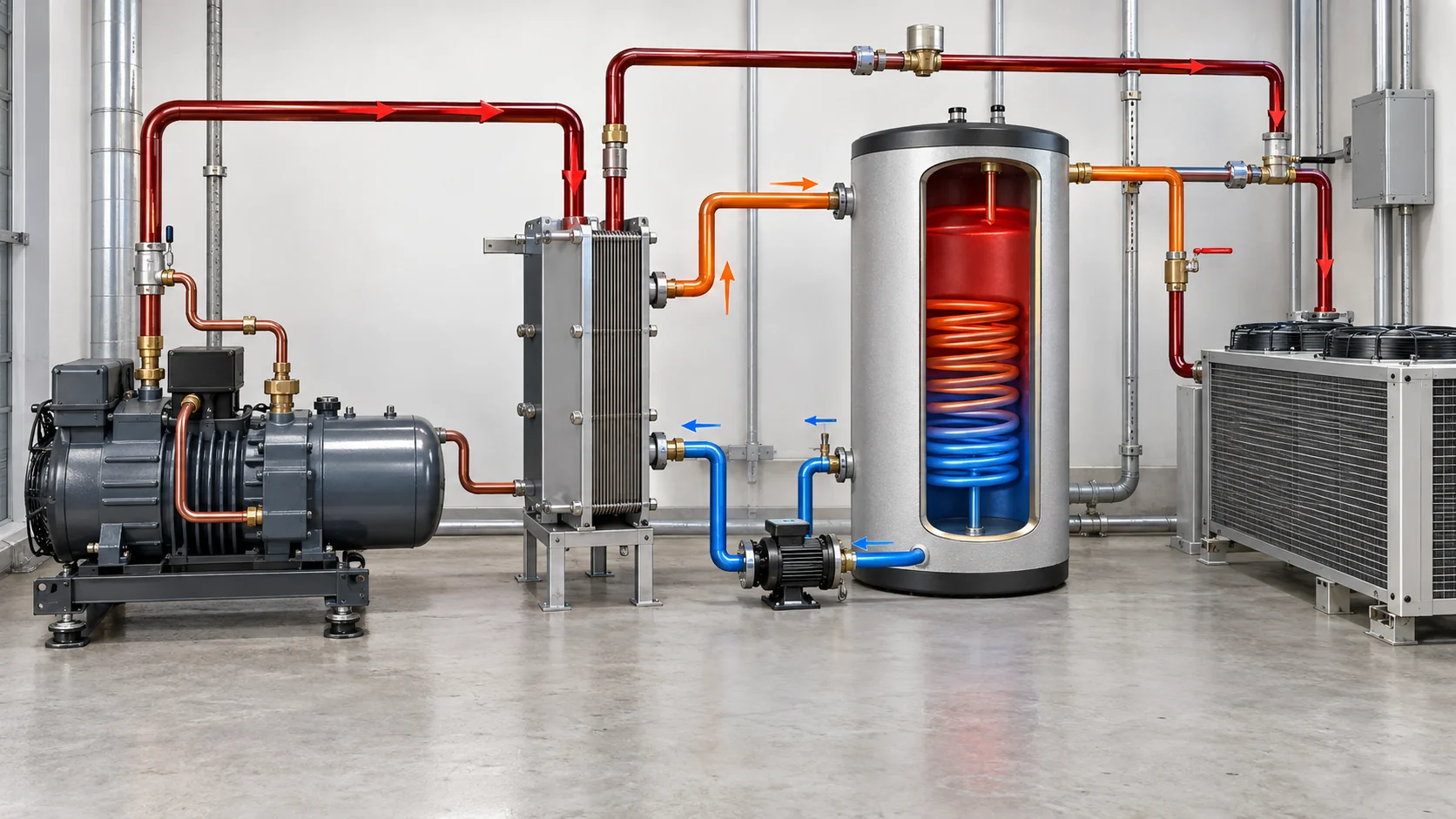
What a heat recovery system does in refrigeration
In a vapor-compression system, the compressor adds work to the refrigerant. The condenser then rejects the refrigerant-side heat to air, water or another sink. A heat recovery system diverts part of that rejected heat through a heat exchanger to a controlled water, glycol or process-fluid loop before the remaining heat reaches the normal condenser.
The useful heat is not a free, constant-temperature utility. Its temperature depends on the refrigerant, compressor operating point, condensing pressure, superheat, subcooling, mass flow and the selected heat exchanger approach. The recovery loop also has a pump, valve, expansion volume, sensors, relief protection and a safe fallback when the hot-water demand disappears.
Danfoss describes heat reclaim as a way to reuse refrigeration heat for space heating and hot tap water, with buffering used to manage timing and load changes. Read the Danfoss heat-reclaim technology guide for that system-level context. The guide is a technology reference, not proof that a particular project can reach a stated temperature or annual saving.
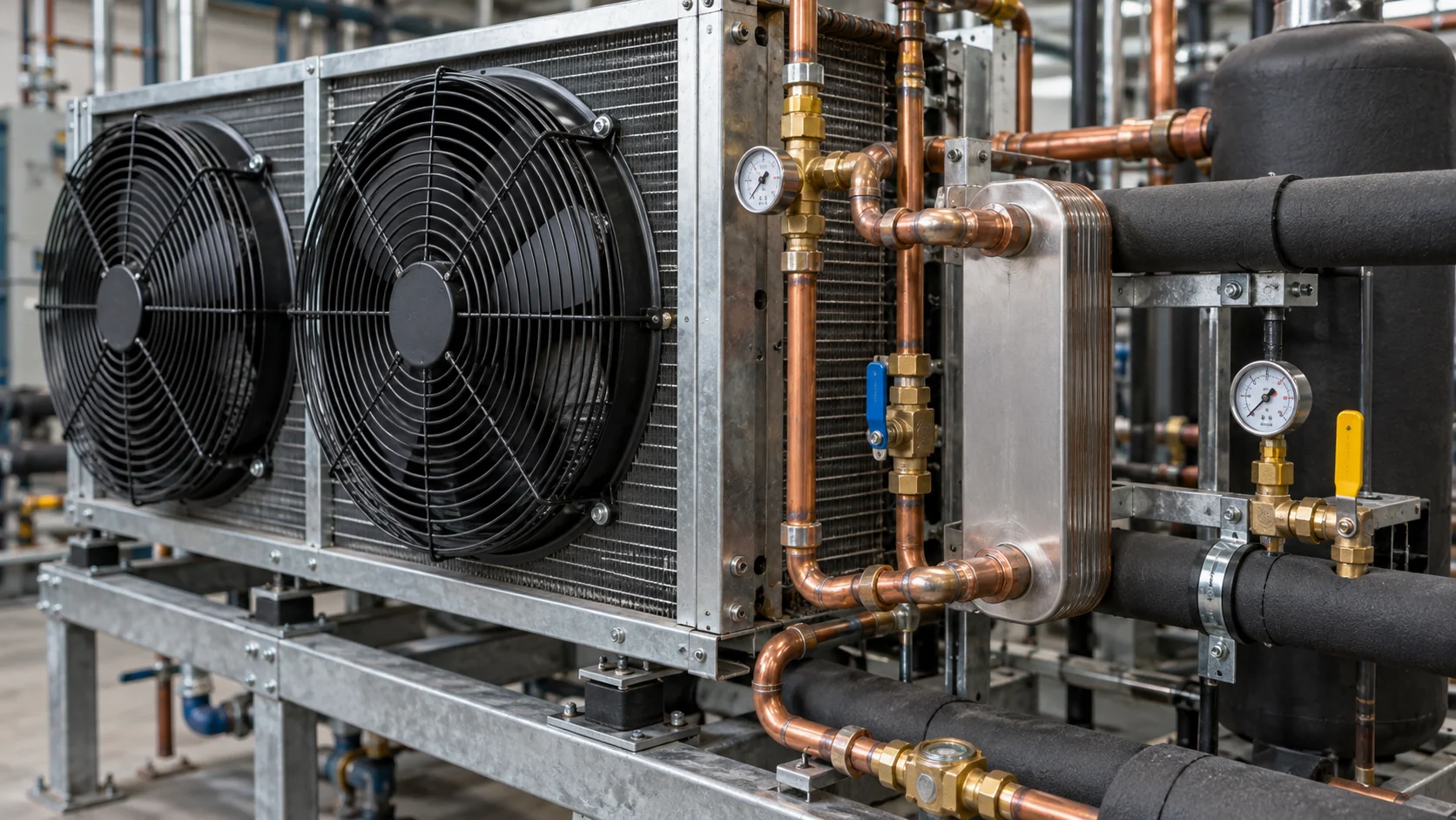
Compare the three practical recovery arrangements
The right arrangement depends on the useful temperature, the amount of heat required, and how often the load overlaps refrigeration operation.
| Recovery route | Heat source and boundary | Best fit | Main design caution |
|---|---|---|---|
| Desuperheater or partial recovery | Superheated discharge gas transfers sensible heat before the main condenser | Preheating water when a modest temperature rise is useful and refrigeration runs during the demand window | Available duty varies with compressor load; the remaining condenser must still reject all heat safely |
| Condenser-side liquid recovery | A refrigerant or condenser-water exchanger transfers a larger share of heat rejection | Stable hot-water or process-water demand with a defined flow and temperature approach | Higher condensing pressure can increase compressor power if the recovery sink cannot accept heat |
| Full-condensing recovery with storage and bypass | The recovery exchanger acts as the main condenser when the heating loop is available, with a normal condenser as backup | Sites with a dependable heating load, storage volume and coordinated controls | Requires head-pressure control, relief protection, isolation, bypass logic and a verified fallback mode |
Desuperheater or partial recovery
A desuperheater removes part of the discharge-gas superheat. It is often the least disruptive retrofit because the existing condenser remains the final heat-rejection device. This route can preheat incoming water or a closed process loop without asking the recovery exchanger to condense the full refrigerant flow.
The trade-off is temperature and capacity. A desuperheater may deliver a useful preheat stage, but it should not be presented as a stand-alone high-temperature heater unless the refrigerant and operating envelope support that claim. Check discharge temperature, oil return, pressure drop, design pressure and the expected duty at minimum compressor loading.
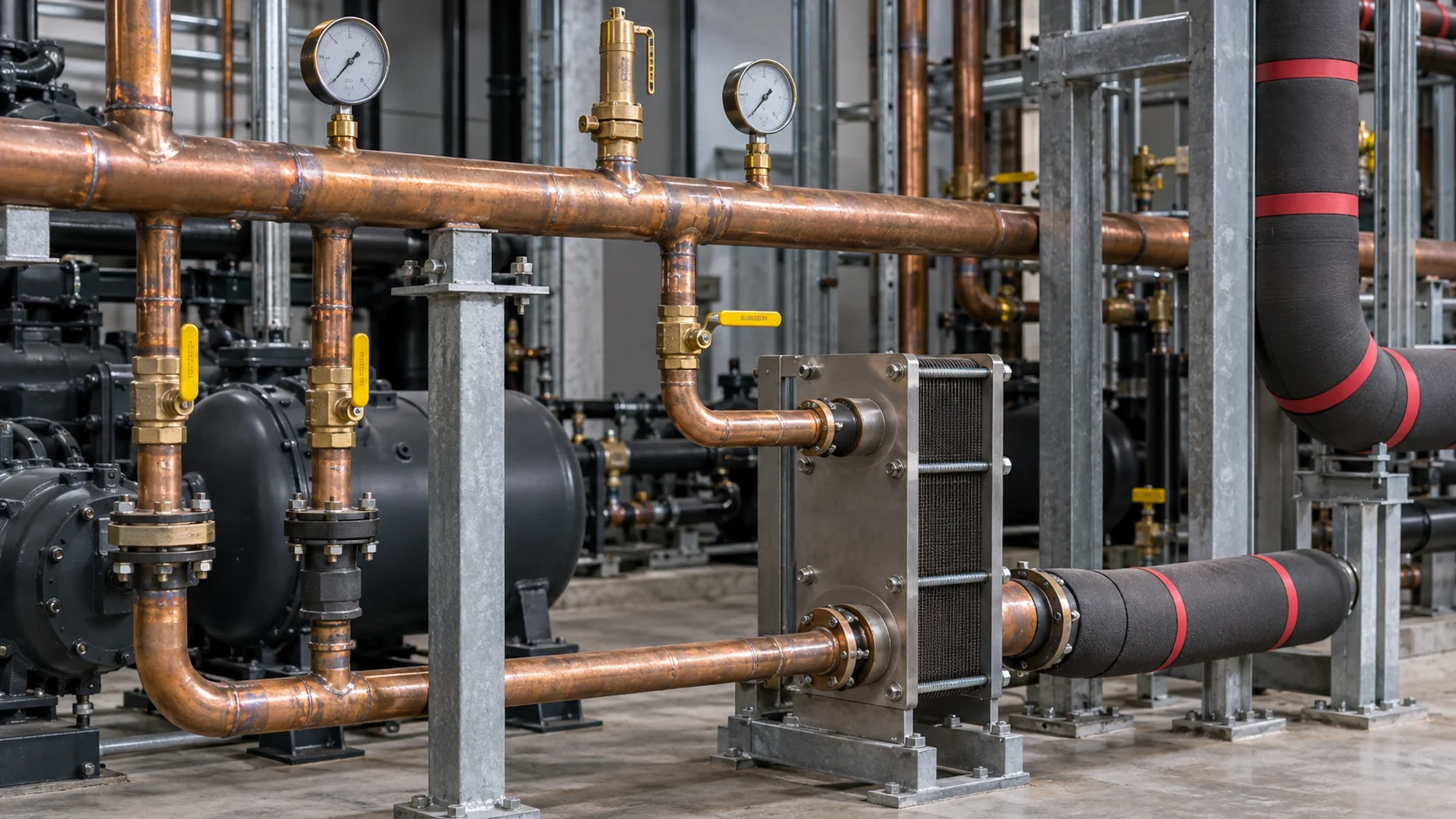
Condenser-side or liquid-to-liquid recovery
A condenser-side recovery exchanger can capture more of the heat rejected by the refrigeration circuit. On the secondary side, that may be hot water, glycol, treated process fluid or a building loop. A plate heat exchanger can be compact for clean liquid-to-liquid duties, while a shell-and-tube or welded construction may be more appropriate for higher pressure, contaminated fluids or a service plan that requires a different cleaning method.
Do not combine refrigerant and utility-fluid assumptions in one nominal capacity. The selection sheet should identify every circuit, phase condition, design pressure, temperature approach and allowable pressure drop. If the recovery exchanger is on the refrigerant side, the supplier should also show oil-return assumptions and the effect of the exchanger on compressor and condenser operation.
Full-condensing recovery with storage and bypass
Full recovery can be attractive where the heating load is dependable and the water loop can accept the heat at the refrigeration design point. A storage tank helps when heating demand is intermittent, but storage does not remove the need for a bypass. If the tank is hot, the process is idle, or a pump trips, the refrigeration system still needs a safe heat-rejection path.
California Energy Design Assistance describes partial and full heat-reclaim arrangements and emphasizes coordinated three-way valves, storage and controls. Its refrigeration heat-reclaim technical guide is useful for comparing the control boundary, while local codes, pressure rules and the equipment manufacturer remain authoritative for a release decision.
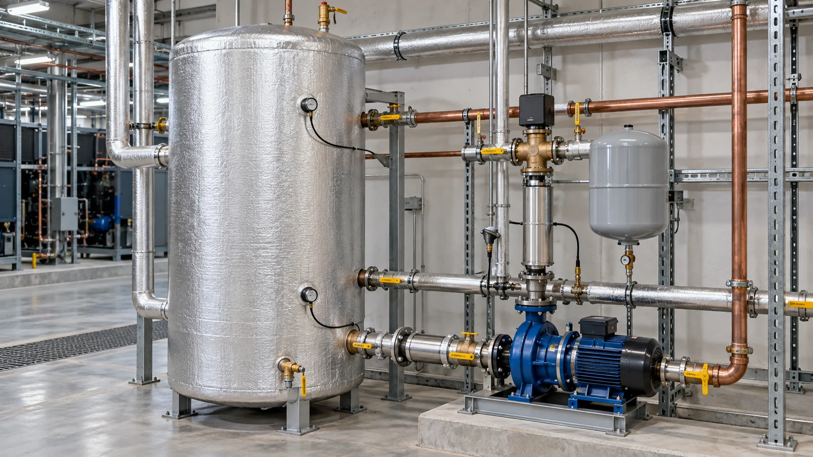
Size useful heat before selecting hardware
For a single-phase utility loop, start with the heat balance:
Useful heat transfer rate = mass flow × specific heat × temperature rise.
The fluid properties must match the actual water, glycol or process fluid. A water-only calculation can overstate heat transfer when glycol, oil or another fluid has a lower specific heat. For the refrigerant side, use the compressor and condenser operating data rather than assuming that all electrical input becomes useful hot water.
Send normal, minimum and peak cases. A recovery exchanger selected only at peak load may be difficult to control during low load. A unit selected only at a mild ambient may not maintain the expected hot-water temperature on a high condensing-temperature day. Include startup, defrost, pull-down and emergency cases when they change the heat balance.
| Design input | Minimum information to send | Why it changes the selection |
|---|---|---|
| Refrigeration duty | Normal and design cooling load, refrigerant, suction and condensing conditions, compressor staging | Sets the available heat, flow range and safe operating envelope |
| Useful heating duty | Required heat rate, supply and return temperature, minimum and peak demand, operating hours | Determines whether partial recovery, full recovery or storage is appropriate |
| Fluid and flow | Water, glycol or process-fluid identity, concentration, density, viscosity, mass or volume flow | Drives heat capacity, material compatibility and pressure drop |
| Hydraulics | Allowable pressure drop on both sides, pump curve, control-valve authority and minimum flow | Prevents a thermal selection that cannot be operated by the installed pump or valve |
| Site boundary | Ambient, elevation, utilities, noise, installation space, drainage and access | Determines condenser fallback, supports, service clearance and controls interfaces |
The Domi plate heat exchanger selection guide explains why heat duty, flow, approach temperature, fouling allowance and pressure drop must be rated together. Use that same discipline for a heat recovery exchanger. A low purchase price is not a valid comparison if one quote hides the fluid properties or pressure-drop assumption.
Select the heat exchanger, materials and pressure boundary
Plate heat exchangers are compact and can provide a close temperature approach for clean liquid-to-liquid loops. Gasketed frames allow inspection and cleaning, while brazed plates reduce footprint but need a clear replacement plan if channels foul. Shell-and-tube units can offer familiar tube-side service for some high-pressure or contaminated duties. Finned coils are a different interface and belong on the air side, not in a liquid-to-liquid RFQ by default.
| Construction | When it may fit a heat recovery duty | Evidence to request before release |
|---|---|---|
| Gasketed plate-and-frame | Clean water or glycol loops that need inspection, gasket replacement or future plate changes | Plate and gasket materials, design and test pressure, fouled rating, service clearance and cleaning method |
| Brazed plate | Compact sealed water, brine or packaged heat-recovery assemblies | Braze alloy, fluid compatibility, maximum pressure and temperature, replacement route and allowable pressure drop |
| Welded or semi-welded plate | Refrigerant service, cyclic duty, higher pressure or aggressive fluids | Weld inspection, pressure code, relief arrangement, fatigue limits and repair plan |
| Shell-and-tube | Duties that need tube access, robust construction or a site-standard maintenance method | Tube and shell materials, pass arrangement, cleaning access, vibration limits and full heat-balance rating |
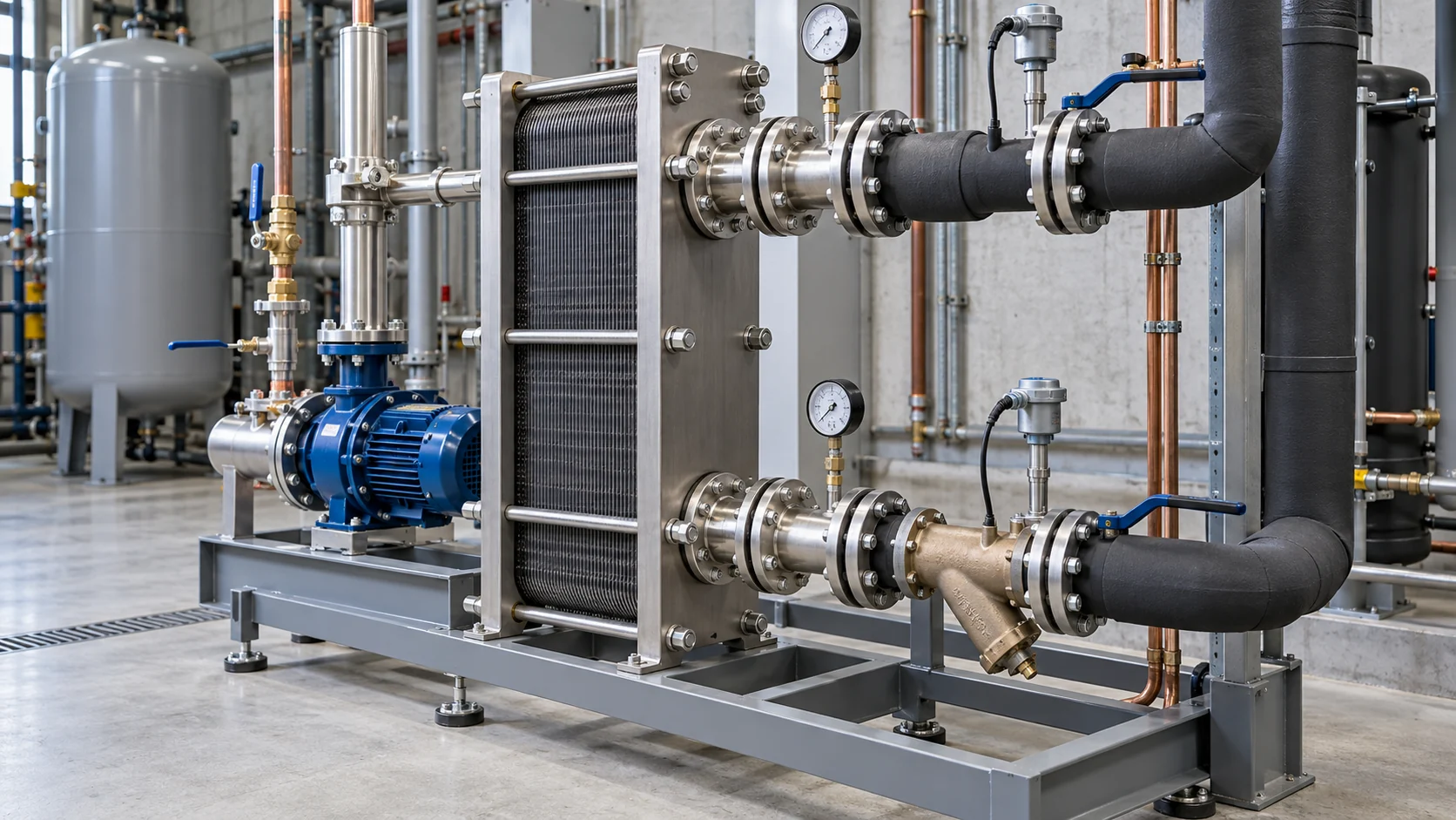
Material compatibility is a project requirement, not a generic “industrial grade” label. State water chemistry, chloride, pH, dissolved solids, oxygen, glycol or brine concentration, refrigerant, oil, cleaning chemicals and temperature cycling. Confirm copper, stainless steel, brazing material, gasket compound, elastomers, valve seats and sensor wells as one compatibility set.
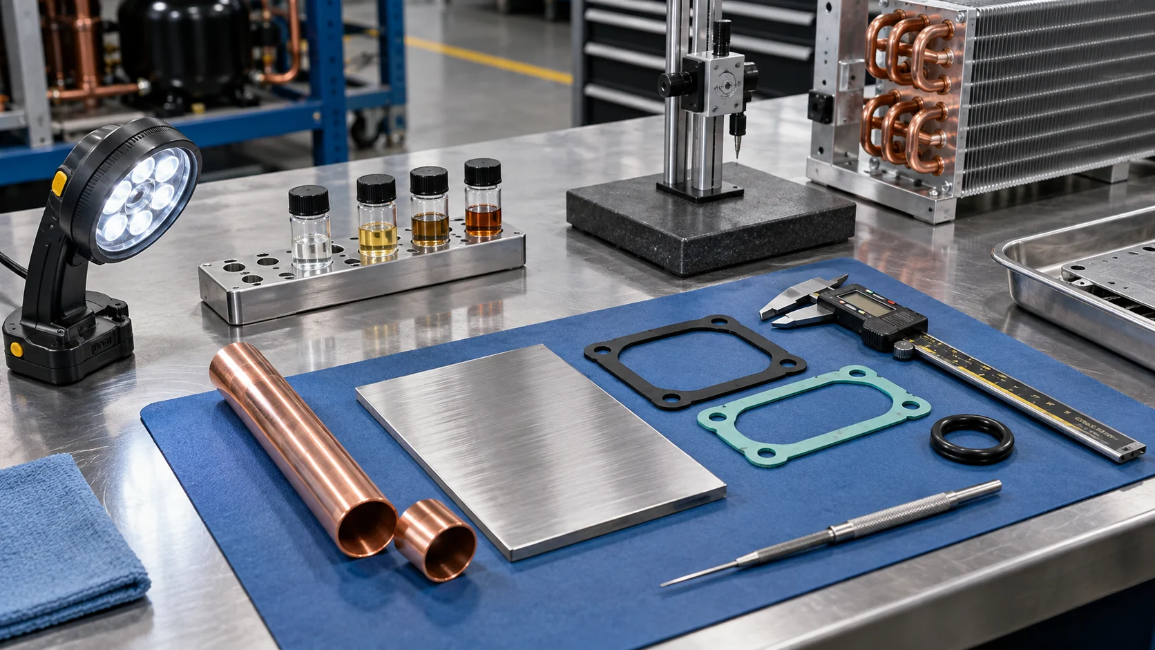
For refrigerant-side recovery, confirm design pressure, test pressure, relief set points, refrigerant classification, oil return and allowable pressure drop. For a potable or hygienic hot-water loop, keep the recovered fluid boundary separate from the refrigerant circuit and confirm the applicable hygienic, pressure and water-safety requirements with the responsible engineer. A heat recovery article cannot grant those approvals.
Design controls, storage and safe fallback
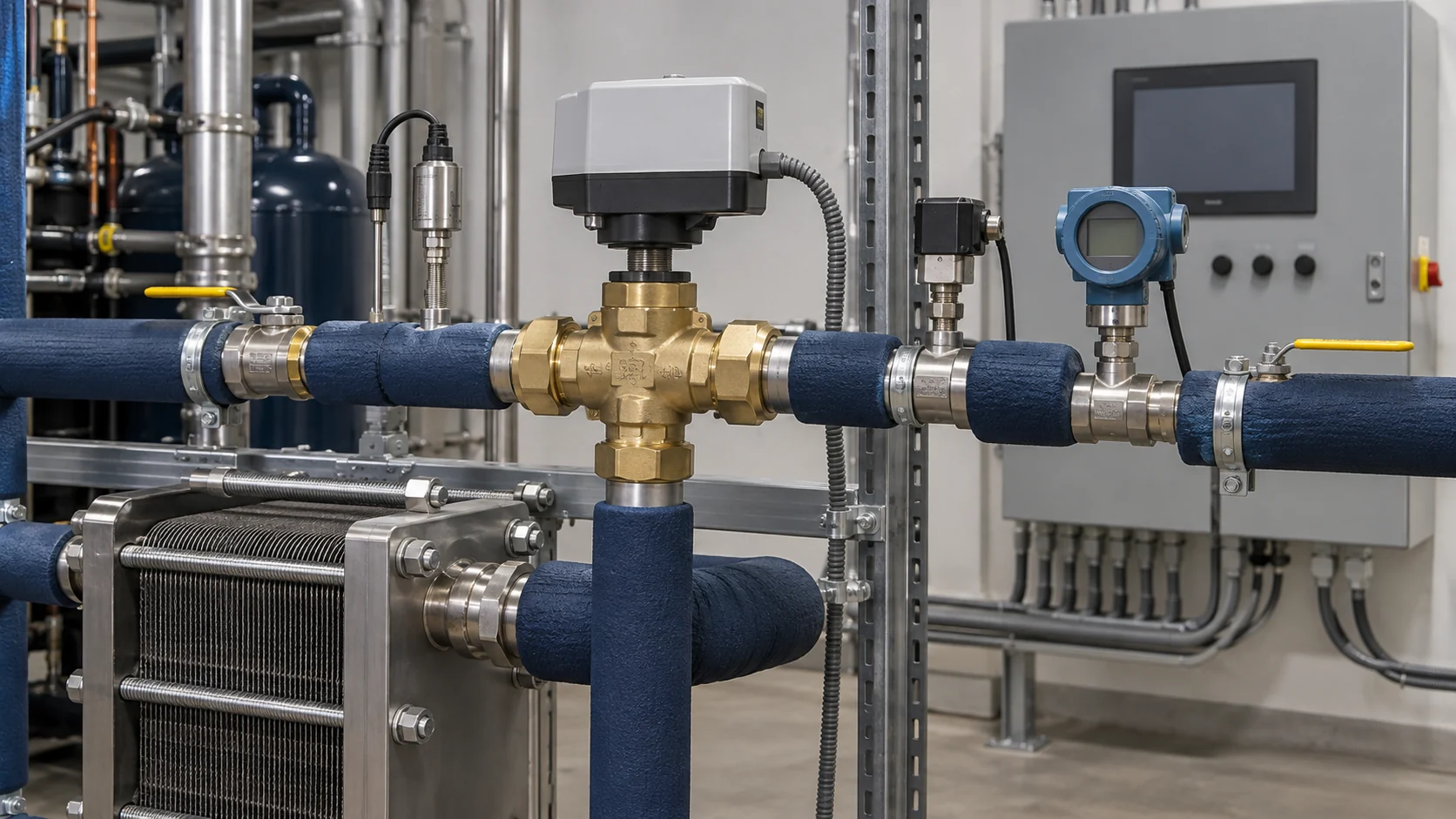
A three-way valve may divert the heating fluid, refrigerant or condenser-water path depending on the selected architecture. The control sequence should state what happens when the tank is satisfied, the hot-water pump loses flow, a sensor fails, the heat exchanger approaches its pressure-drop limit, or the refrigeration rack falls below its minimum stable condition.
Use independent temperature and flow proof where loss of circulation could freeze a liquid side or overheat a component. Trend entering and leaving temperatures, differential pressure, valve position, compressor stage and condenser pressure during commissioning. Set the normal condenser or dry cooler as a real fallback, not as a line that is assumed to work without a control sequence.
| Control or protection item | Normal function | Acceptance evidence |
|---|---|---|
| Three-way diverting or bypass valve | Sends heat to the recovery loop when the heat sink is available and returns to safe heat rejection when it is not | Stroke test, fail position, response time and trend record |
| Hot-water or process-fluid pump | Maintains the rated flow through the recovery exchanger | Measured flow, motor current, minimum-flow proof and alarm test |
| Temperature sensors | Protects the useful loop and confirms the heat balance | Calibration check, sensor location and supply/return trend |
| Pressure and relief devices | Keeps refrigerant and utility circuits within their design boundary | Set points, test records, discharge routing and isolation review |
| Storage and mixing controls | Absorbs timing mismatch and limits delivery temperature | Tank recovery test, high-temperature cutout and mixing-valve response |
| Normal condenser fallback | Rejects heat when recovery demand is absent or unavailable | Manual and automatic bypass test at low and high load |
Storage volume should come from the timing mismatch between available recovery heat and useful demand. Do not select a tank only because it fits the room. Include usable volume, insulation, expansion volume, pump head, mixing, drain points, service access and the maximum allowed delivery temperature.
Applications where heat recovery can fit
Food and beverage plants often have simultaneous refrigeration, wash-water and process-water demand. The useful design question is whether the heat-recovery fluid stays separated from product-contact surfaces and whether the sanitation schedule matches the available heat. A food-grade fluid does not make every connected pipe, gasket or heat exchanger food-contact compliant.
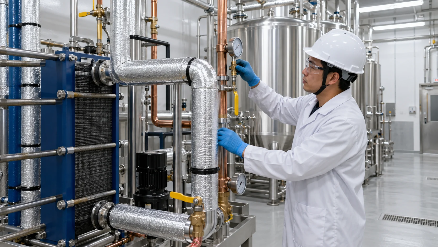
Cold storage and distribution sites can use recovered heat for space heating, dock areas, defrost support or utility water, but the duty changes with door openings, product pull-down and seasonal storage patterns. A compressor rack may provide useful heat for many hours, then require a normal condenser when the utility loop reaches its target.
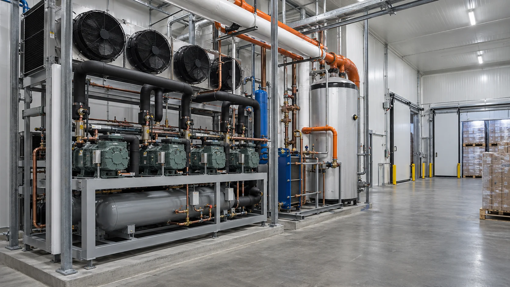
Other possible applications include ice-making, refrigerated warehouses, process-cooling plants, restaurants, supermarkets, heat-pump interfaces and industrial wash systems. Screen each one against four questions:
- Is the heating demand present while the refrigeration system is operating?
- Is the required temperature below, near or above the available recovery temperature?
- Can the secondary loop accept variable heat without upsetting refrigeration control?
- What is the safe heat-rejection mode when the heating load is absent?
The Energy Code Ace reference on commercial refrigeration heat recovery is a useful reminder that a recovery condenser and its heating coil must be coordinated with condensing temperature and the complete HVAC or refrigeration load. It should not be treated as a universal industrial design rule.
Commissioning and maintenance checks
Commissioning should prove the heat balance and fallback sequence, not only that the pump starts. Record refrigerant-side pressure and temperature, utility-side entering and leaving temperature, flow, differential pressure, compressor stage and condenser control at normal, low and high load. Confirm that the heat sink receives the intended temperature without causing unstable head pressure or an unexpected pump penalty.
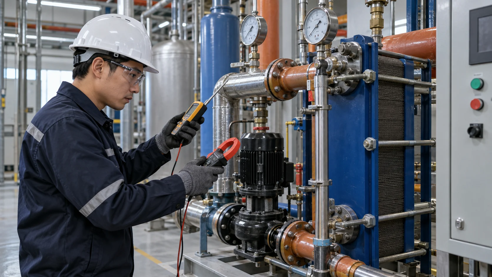
Maintenance should follow measured change. Trend approach temperature and differential pressure against a clean baseline. Rising approach temperature with rising pressure drop can indicate fouling, a blocked strainer, low flow or a control valve problem. Check fluid chemistry, inhibitor level, gasket condition, insulation, sensor calibration and relief-device records according to the equipment and site procedures.
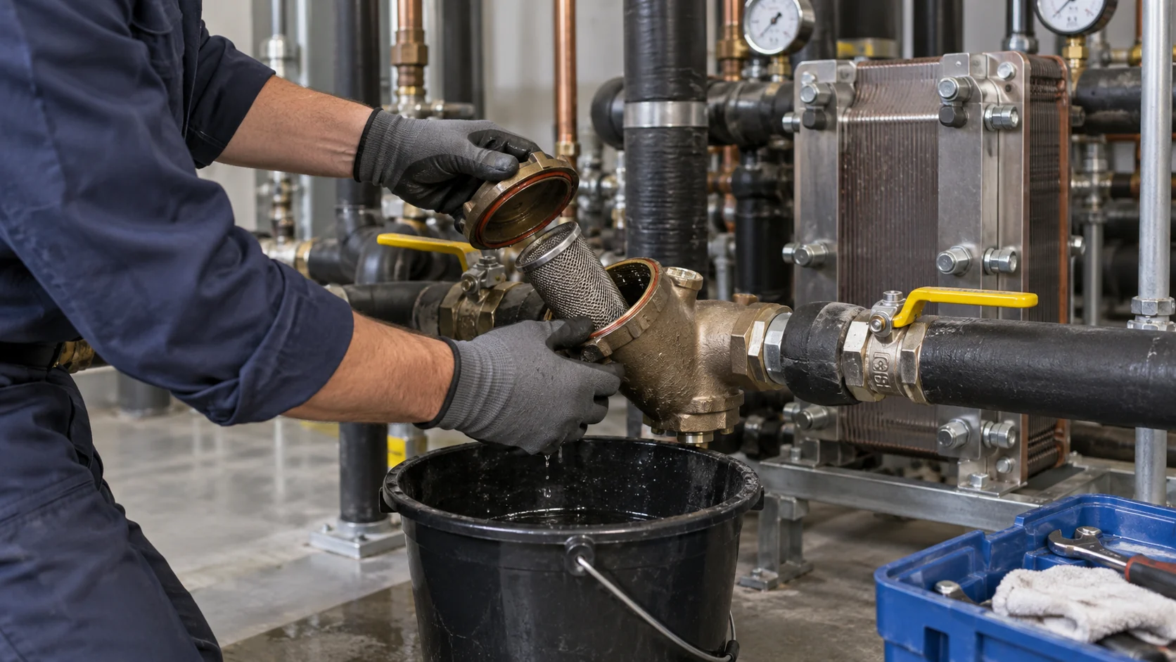
Make service access part of the layout. A gasketed plate frame may need a pull-out distance larger than the skid footprint. A shell-and-tube head may need lifting space. A strainer needs isolation and drainage. A storage tank needs relief discharge routing and a safe way to inspect or replace sensors.
RFQ checklist for a heat recovery system
Send one controlled package rather than a nominal “heat recovery unit” request. Include:
- Refrigerant, compressor type, normal and design cooling duty, suction condition, condensing condition and operating schedule.
- Available recovery source, estimated heat-rejection profile and the portion of heat intended for recovery.
- Useful heating fluid, flow, inlet and outlet temperatures, minimum and peak demand, and whether the loop is open, closed, hygienic or potable.
- Design and test pressure, design temperature, pressure-drop limit and relief requirements for every circuit.
- Fluid chemistry, glycol or brine concentration, contaminants, cleaning method and material restrictions.
- Storage volume, mixing arrangement, pump curve, control-valve type, sensor points, PLC or BAS interface and alarm list.
- Normal condenser or dry-cooler fallback, bypass logic, fail positions and the response to a lost pump or full tank.
- Connections, orientation, footprint, service clearance, lifting path, insulation, drainage, noise and installation environment.
- Required drawings, material certificates, pressure-test records, inspection points, spare parts and packaging.
- Quantity, redundancy, target delivery location and the acceptance test that will be used to compare the quotation.
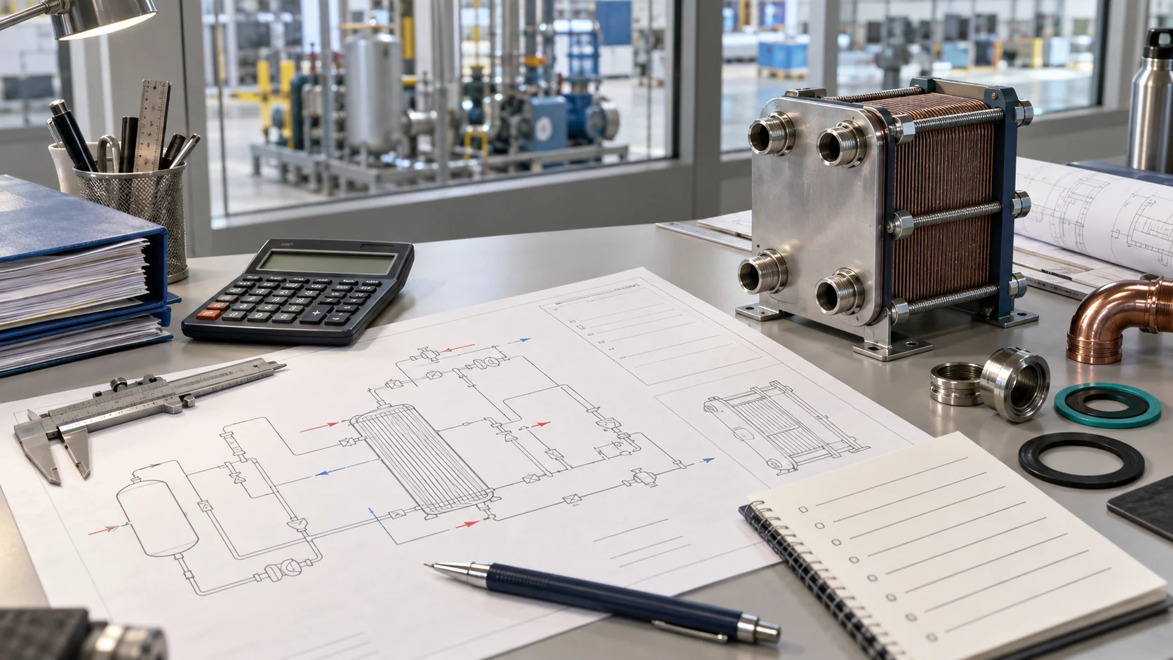
Heat recovery mistakes that create hidden cost
Several failure modes are predictable before the first pipe is installed:
- Sizing by rejected heat only: the recovery loop cannot use heat that it cannot accept at the required temperature and flow.
- Ignoring low-load operation: a recovery exchanger can be oversized for the hours when the compressors stage down.
- Raising condensing pressure without a heat sink: compressor power rises while the useful loop is already full or offline.
- Skipping fluid chemistry: a compact exchanger fouls or corrodes because the water, glycol, oil or cleaning chemical was never stated.
- Leaving out the bypass: the refrigeration system has no safe heat-rejection mode during a pump trip, sensor fault or satisfied tank.
- Treating the component as the whole system: valves, pumps, storage, sensors, relief protection and controls determine whether the recovered heat is usable.
Before you request a quote
A defensible heat recovery system selection can be reduced to five checks: the heating demand overlaps refrigeration operation, the useful temperature is realistic, the heat exchanger is rated for both circuits, the controls have a tested fallback, and the RFQ states every assumption that affects pressure, materials, service and acceptance. If one of those checks is missing, ask the supplier to list the assumption rather than hiding it in a nominal capacity.
From recovery duty to a reviewable thermal package
Domi Refrigeration can review the heat-transfer portion of a refrigeration or process-cooling project using the duty data, fluid information, drawings, installation envelope and documentation requirements you provide. The relevant path may be an industrial refrigeration coil, a custom heat exchanger component, a condenser-side assembly or another construction selected from the actual boundary conditions. Domi does not assume that every request is a complete heat-recovery skid, so the quotation should define the supplied component, interfaces and evidence.
For a technical review, start with industrial refrigeration solutions or custom coil fabrication. Send the refrigeration duty, useful heat demand, fluids, temperatures, flow, pressure limits, controls interface, drawings or sample photos and service constraints. When you are ready to align the component with the project, contact Domi’s thermal team with the RFQ package.
Frequently asked questions
What is a heat recovery system in refrigeration?
A heat recovery system transfers part of the heat rejected by a refrigeration circuit to a controlled water, glycol or process-fluid loop. It normally includes a recovery heat exchanger, valves, sensors, pump or flow proof, safety devices and a normal condenser fallback. The useful temperature and capacity depend on the refrigerant and operating conditions.
Is a heat recovery system always energy efficient?
No. It can reduce separate heating demand when the useful heat load overlaps refrigeration operation, but an undersized heat sink, excessive condensing pressure, high pump power or poor controls can remove the benefit. Compare delivered useful heat and total system power at the same operating boundary.
What is the difference between a desuperheater and full heat recovery?
A desuperheater removes discharge-gas superheat while the normal condenser still rejects the remaining heat. Full recovery uses a larger recovery boundary, often with storage and a bypass, to transfer more of the condenser duty when the heating loop is available. The choice depends on temperature, load overlap, pressure drop and control requirements.
Can a plate heat exchanger be used for refrigeration heat recovery?
Yes, when its construction, refrigerant or fluid boundary, design pressure, materials, phase behavior, oil return, pressure drop and service plan are suitable. A gasketed, brazed, welded or semi-welded design may fit different duties. The supplier should return a rated selection rather than a plate count alone.
Do I need a storage tank for heat recovery?
Not always. Storage helps when useful heating demand and refrigeration operation do not occur at the same time or when the demand changes quickly. A tank adds volume, insulation, pump head, mixing, relief and service requirements, so it should be sized from the timing mismatch and operating temperatures.
What should I send a supplier for a heat recovery RFQ?
Send the refrigerant and compressor data, normal and design cooling loads, useful heating duty, fluid identity and concentration, inlet and outlet temperatures, flow, pressure-drop limits, design pressure and temperature, storage and controls requirements, bypass logic, installation envelope, drawings, inspection documents and delivery needs. Include low-load and fallback cases when they affect the selection.