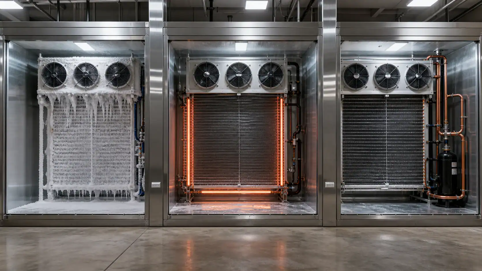
For commercial freezers and cold rooms, refrigeration defrost normally falls into three practical choices: off-cycle air defrost, electric defrost, or hot-gas defrost. The correct method depends on evaporating temperature, frost load, room humidity, system scale, available electrical capacity, controls, drainage, and total operating cost. A medium-temperature room may use off-cycle defrost, while a low-temperature freezer usually needs a positive heat source from an electric heater or a hot-gas circuit.
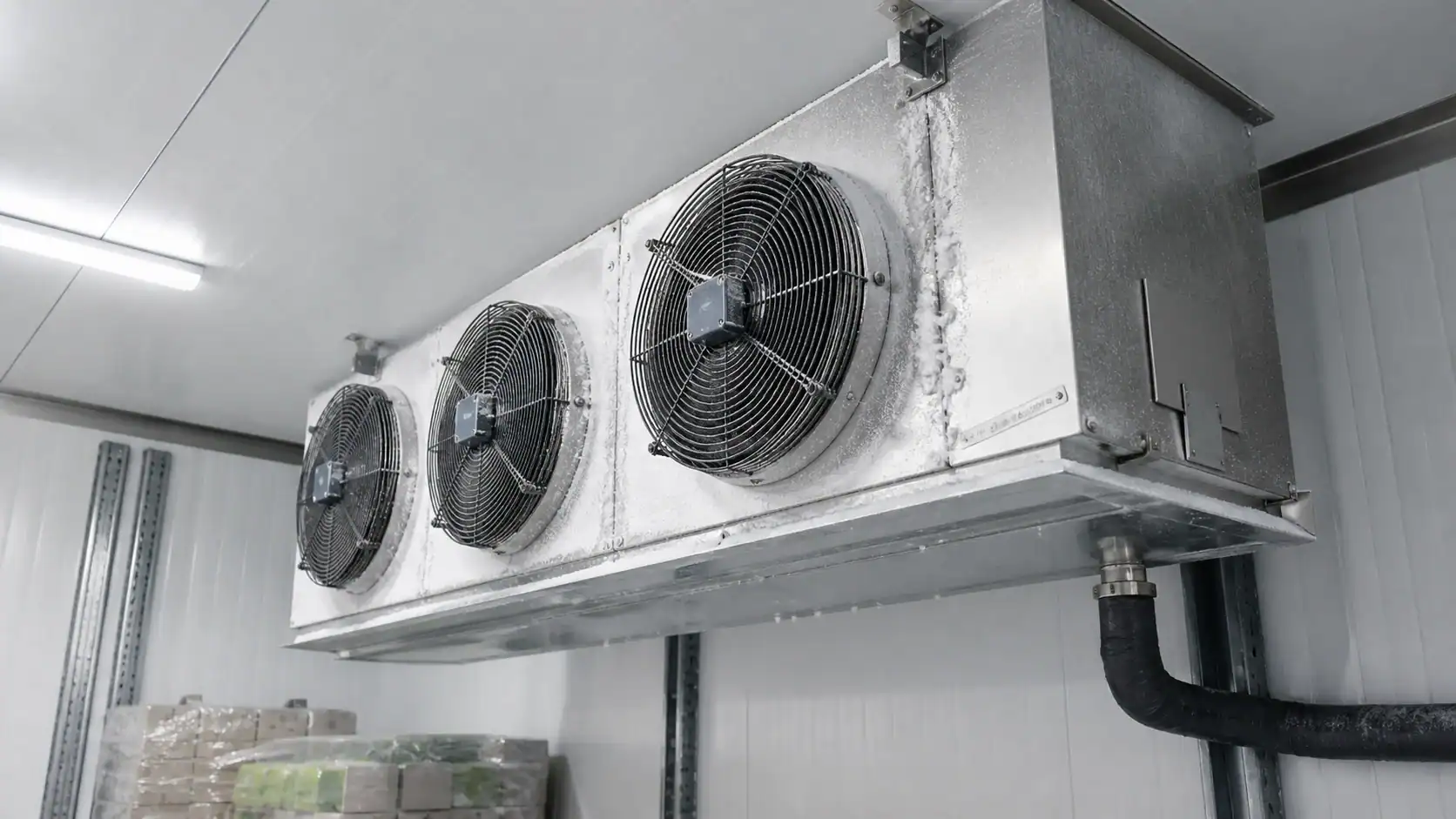
What refrigeration defrost does
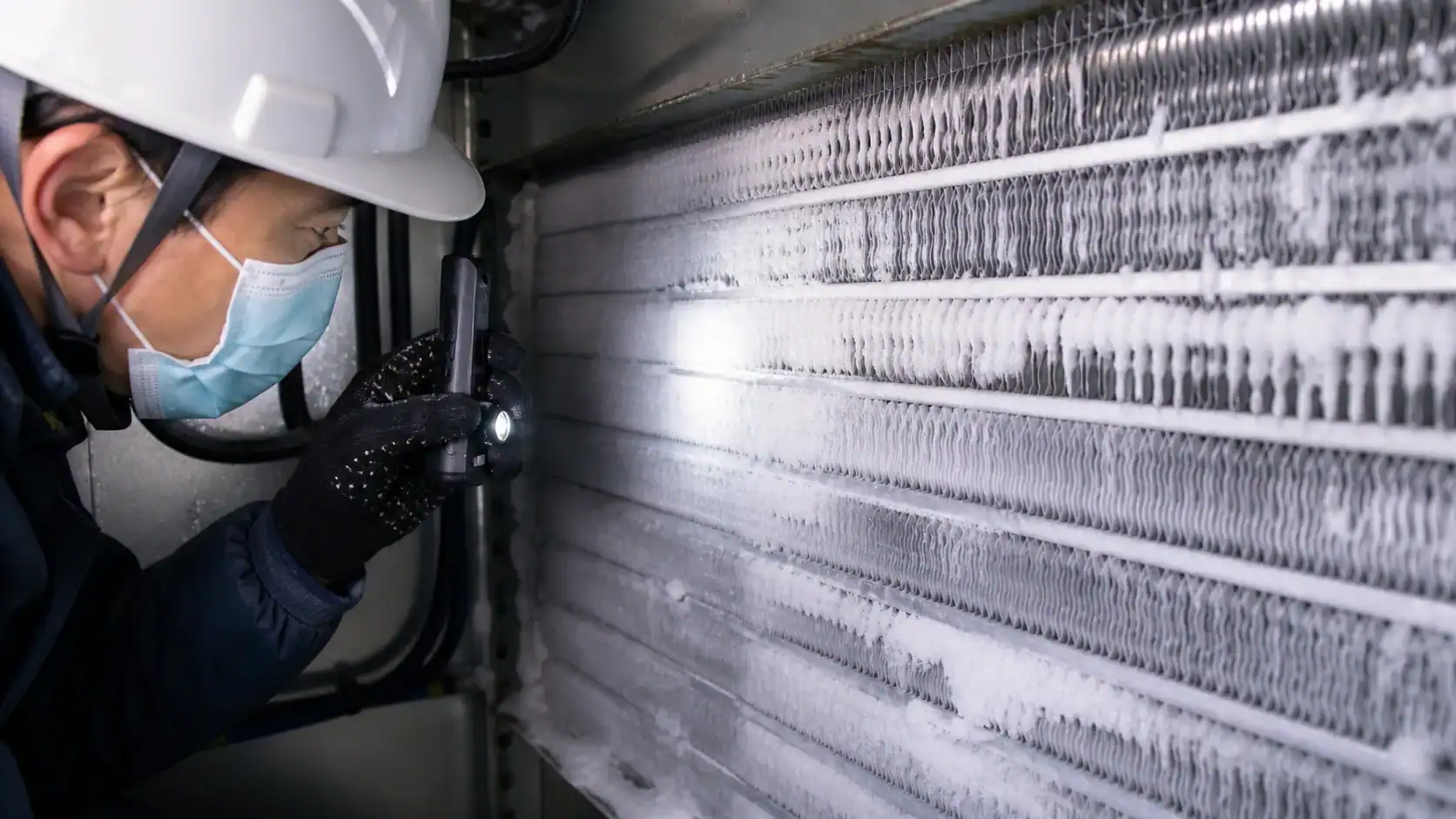
When a coil operates below the dew point, moisture from infiltration, door openings, product loading, and washdown can freeze on the fins. Ice narrows the air passages, raises air-side resistance, reduces heat transfer, changes fan duty, and can block the drain pan. Defrost is the controlled removal of that ice so the evaporator can return to its intended airflow and capacity.
The objective is not to make the coil hot. It is to deliver enough heat to melt the actual frost load, terminate at the right condition, drain the water, and restart refrigeration without a product-temperature excursion. The article on unit cooler selection for cold rooms covers the related assembly inputs, including fin spacing, fan duty, drain arrangement, and defrost coordination.
The three methods at a glance
| Method | Heat source | Typical application | Main advantage | Main limitation |
|---|---|---|---|---|
| Off-cycle or air | Warmer room air after refrigeration stops | Medium-temperature rooms and cases | Lowest component count and electrical demand | Too slow when the room and coil remain deeply below freezing |
| Electric | Resistive heaters around or through the evaporator | Small and medium low-temperature systems | Predictable, compact, and straightforward to service | Adds peak electrical load and heat to the space |
| Hot gas | High-pressure refrigerant vapor condensed in the coil | Larger commercial and industrial systems | Fast heat transfer with less heater-bank demand | Requires valves, piping, controls, and careful pressure management |
Off-cycle defrost for medium-temperature applications
Off-cycle defrost stops refrigeration and allows the evaporator to warm from the room and surrounding equipment. Fans may remain off during the first part of the cycle and restart only after meltwater has drained. It is the simplest approach when the room, product, and coil are normally above freezing or only slightly below it.
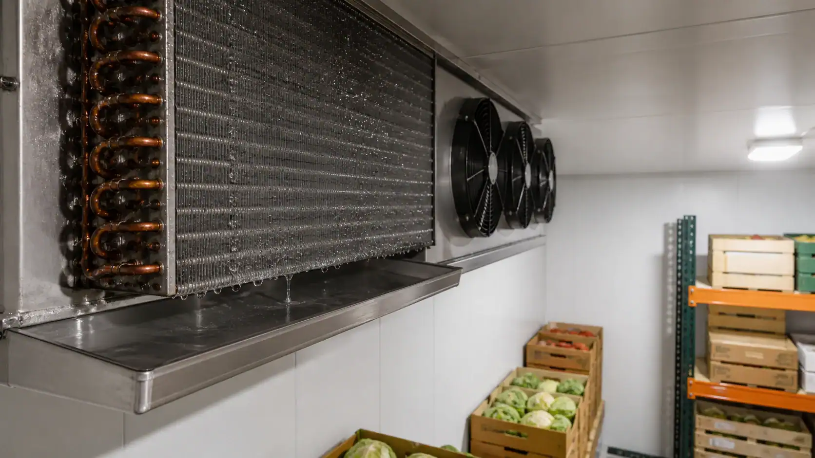
An OEM should investigate off-cycle first when the evaporating condition provides enough temperature difference to melt frost in the allowed recovery time. That keeps the bill of materials small and avoids a heater circuit, but it does not remove the need for a proper drain pan, drain trap, fan restart logic, and a test under realistic door-opening humidity.
Off-cycle is a poor fit for a deep-freeze coil. If the evaporator and room are both far below freezing, the available heat is insufficient and the cycle can leave ice in the fin pack. The result is often rising pressure drop, falling airflow, and a longer recovery period even though the controls report that defrost has completed.
Electric defrost for packaged freezers
Electric defrost places resistive heaters near the fin pack and drain pan. The controller stops refrigeration, energizes the heater circuit, monitors coil temperature, and ends the cycle when the ice has melted or a maximum time is reached. This architecture is common in compact and medium commercial freezer equipment because service technicians understand it and the components are easy to isolate.
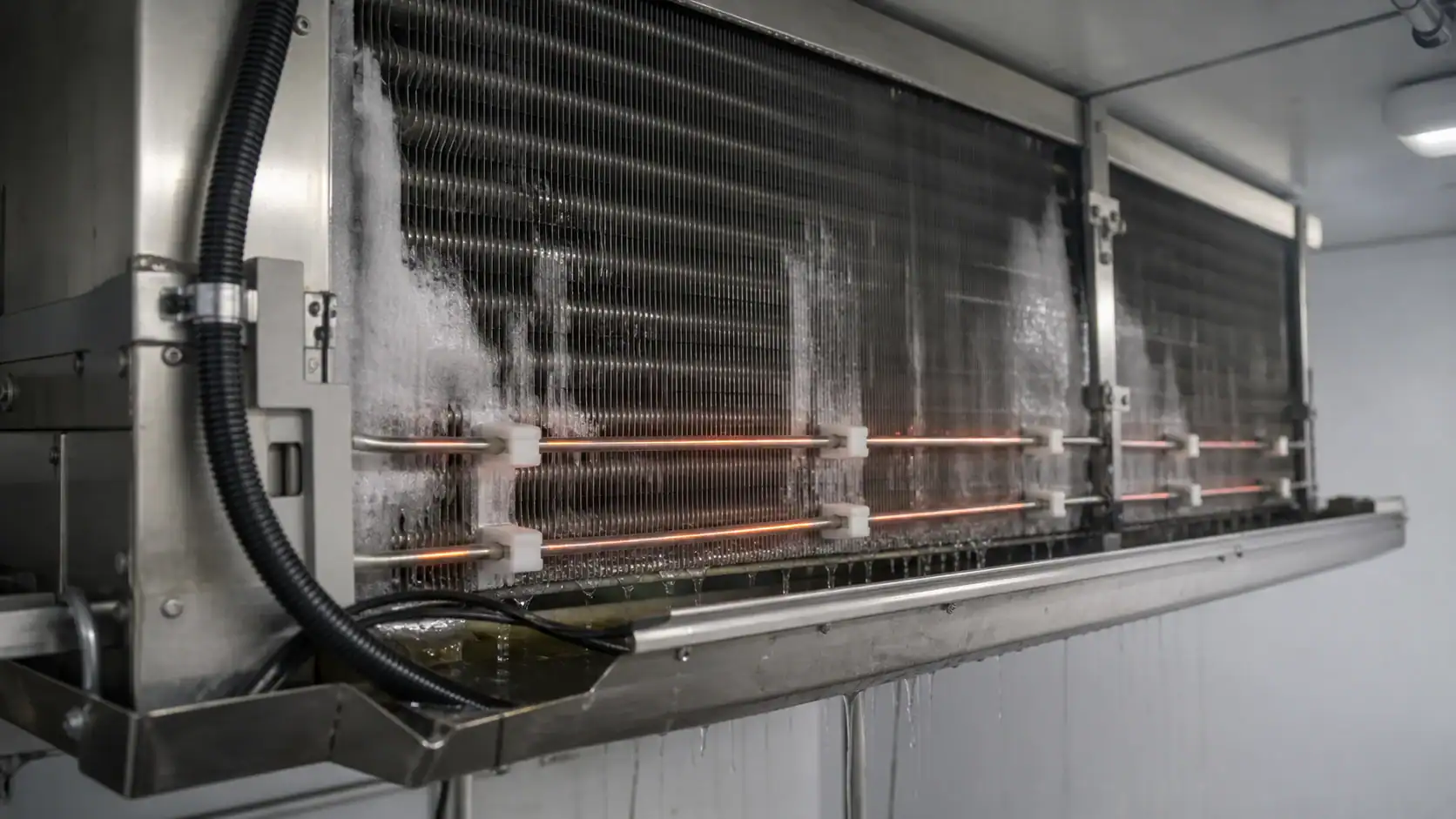
The engineering work is in the details. Heater wattage must match the coil size and frost exposure without overheating the drain pan or nearby materials. The termination sensor should measure the coil condition rather than only the air temperature, and a high-limit safety device should protect against a failed relay or sensor. After heater shutdown, a drip period lets water leave the pan before fans restart and blow droplets onto product.
Electric defrost is attractive when the system is small, the electrical service has spare capacity, and a standardized packaged design matters more than the lowest lifetime energy use. It becomes less attractive when many large evaporators defrost at the same time, the site has a high demand charge, or the added heat causes a significant room-temperature rise.
Hot-gas defrost for larger systems
Hot-gas defrost routes high-pressure refrigerant vapor through an evaporator that normally operates as a cooling coil. The vapor condenses inside the coil and releases latent heat to melt frost from the tube and fin surfaces. A correctly designed circuit can use compressor-generated heat instead of a large electric heater bank.
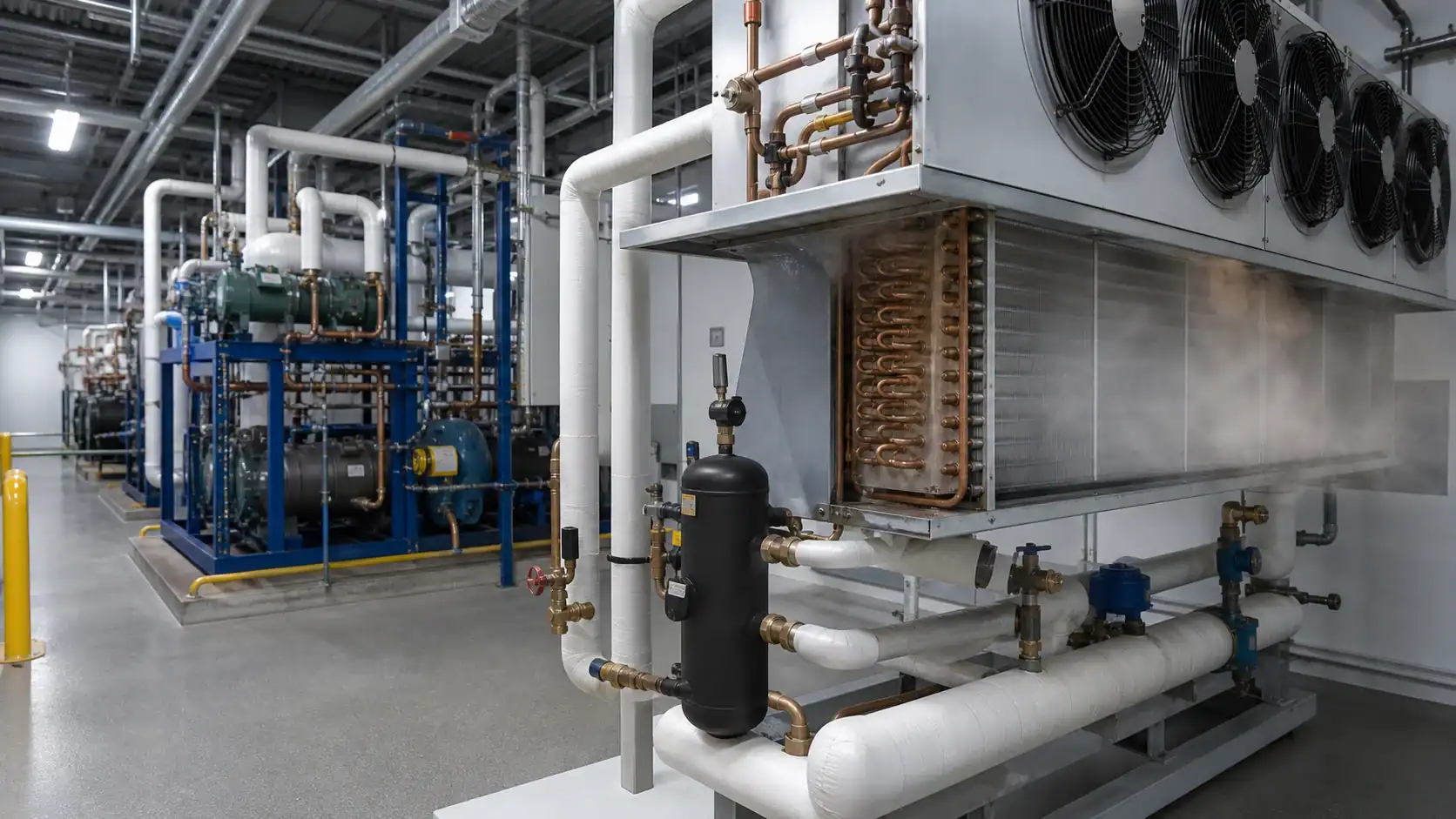
Hot gas becomes more compelling as evaporator size, defrost frequency, and plant scale increase. It can reduce peak electrical demand and shorten the time required to clear heavy frost. It is common to evaluate it for centralized cold rooms, supermarket systems, and industrial refrigeration where multiple evaporators share a plant.
The tradeoff is system complexity. Valve sequencing, pressure equalization, liquid drainage, receiver volume, piping slope, and control interlocks all matter. Poorly sized piping can create pressure shocks, incomplete defrost, or liquid return to the compressor. A supplier quotation should therefore describe the complete circuit and control assumptions, not only the coil connection sizes.
Comparing methods by operating condition
The same evaporator geometry can need different defrost hardware when the room temperature, moisture load, and duty cycle change. Use the table below as a screening tool, then validate the selection in the complete equipment.
| Selection condition | Start with | Why it fits | Checks before release |
|---|---|---|---|
| Medium-temperature room, limited frost | Off-cycle | Room heat can melt the frost without a heater | Melt time, drain capacity, fan restart, recovery temperature |
| Small or medium freezer | Electric | Simple packaged architecture and predictable heat input | Heater kW, sensor location, high-limit cutout, electrical peak |
| Large freezer with repeated heavy frost | Hot gas or staged electric | Faster heat transfer and lower heater-bank demand may justify complexity | Valve sequence, pressure equalization, liquid drainage, controls |
| High humidity or frequent door traffic | Positive heat source with demand logic | Frost load can vary more than a fixed timer assumes | Infiltration test, sensor termination, cycle frequency, water disposal |
Frost load and coil design inputs
Defrost performance begins with the air side. Fin spacing, face velocity, fan selection, and drain-pan geometry determine how quickly frost becomes an airflow problem. The fin spacing guide for low-temperature evaporators explains why a wider fin pitch may be needed when frost exposure is high.
The following inputs should be defined before a coil or unit cooler is released for production:
- Room temperature range and target evaporating temperature
- Product temperature, pull-down requirement, and loading schedule
- Door dimensions, opening frequency, infiltration, and humidity
- Refrigerant, design pressure, circuit arrangement, and expansion device
- Coil face area, row count, tube diameter, fin material, and fin spacing
- Fan airflow, air throw, noise limit, and fan restart interlock
- Defrost heat source, heater wattage or hot-gas path, and cycle frequency
- Termination sensor position, high-limit protection, drip delay, and drain trap
- Drain-pan slope, insulation, heat tracing, and downstream water handling
A practical frost-load review
| Input | What it changes | Evidence to collect |
|---|---|---|
| Infiltration and humidity | Water entering the room and frost accumulation rate | Door schedule, humidity readings, and worst-case opening test |
| Coil temperature | Whether moisture freezes quickly and how much positive heat is needed | Saturated suction condition and coil-surface measurement |
| Fin spacing and face velocity | Pressure drop as ice builds and the time to airflow restriction | Coil drawing, fan curve, and frost-run test |
| Drain and pan design | Whether meltwater leaves before fan restart | Pan slope, trap detail, heater location, and drain test |
| Product sensitivity | Acceptable temperature rise during defrost and recovery | Product specification and pull-down test |
Controls, termination, and drainage
A good refrigeration defrost sequence has separate stages: initiation, refrigeration shutdown, heat application, termination, drip or drain time, fan restart, and refrigeration restart. The controller should use a coil temperature signal or another defensible end condition, with a maximum-time safety limit. A fixed timer alone can over-defrost a lightly loaded coil or under-defrost one exposed to heavy infiltration.
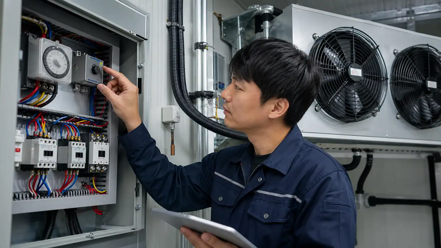
Temperature termination is only useful when the sensor is mounted where it represents the coil. A sensor clipped to a warm frame can end the cycle while ice remains in the fin pack. A sensor buried in a heater shadow can keep the heater on too long. The OEM drawing should show the sensor location, wiring protection, and service access.
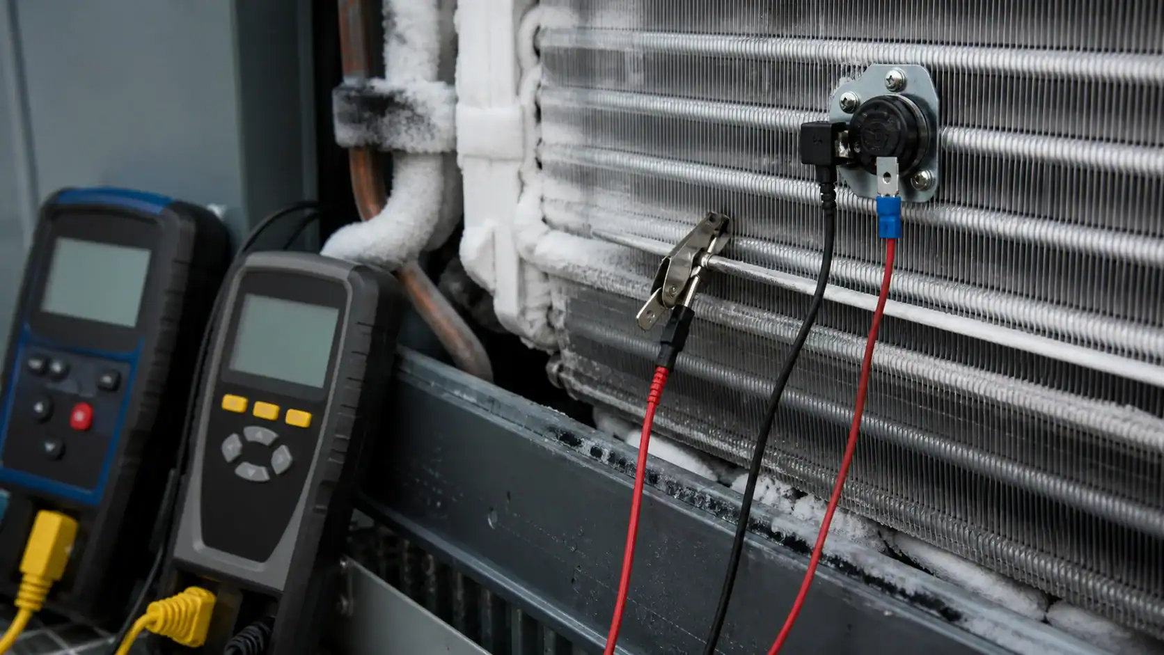
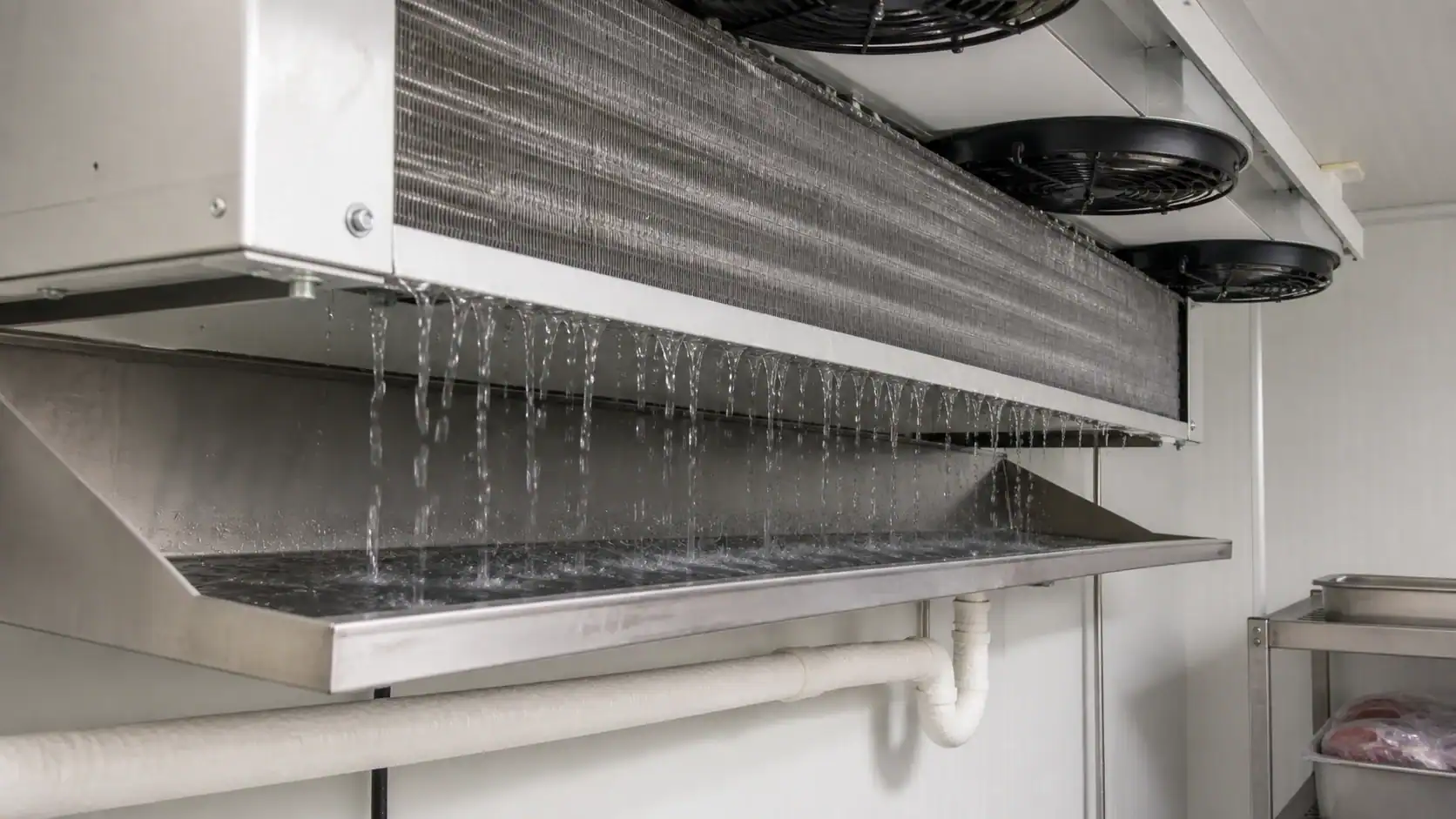
Drainage is part of the defrost system, not a finishing detail. The pan should collect the full meltwater volume, and the drain line should remain open at the lowest expected room temperature. Keep a drip period between heater shutdown and fan restart so water does not become airborne or refreeze at the pan outlet.
| Sequence stage | Control action | Release check |
|---|---|---|
| Initiation | Stop cooling or isolate the evaporator circuit | No conflicting compressor or liquid-feed command |
| Heat application | Energize heaters or open the hot-gas path | Current, pressure, and valve feedback are within limits |
| Termination | End heat on coil temperature or a safe alternate signal | Ice is cleared at the coldest representative location |
| Drip and drain | Hold fans off while meltwater leaves the pan | No standing water or drain-line freeze |
| Fan restart | Restore airflow after the drip delay | No droplets on product and correct fan direction |
| Cooling restart | Return to the normal refrigeration sequence | Pull-down and temperature uniformity meet the requirement |
| Alarm handling | Stop the sequence on high temperature, pressure, or current fault | Alarm is logged and the equipment enters a safe state |
| Manual service mode | Allow an authorized technician to isolate a heater or valve | Service mode cannot bypass high-limit protection |
OEM selection and RFQ checklist
Defrost should be reviewed with the coil, fan, controls, and installation envelope as one package. A supplier can compare electric and hot-gas options only when the duty point and physical constraints are clear.

Send the following with an RFQ:
- A dimensioned drawing or controlled sample with connection orientation and mounting points.
- Room temperature, evaporating temperature, refrigerant, design pressure, and capacity target.
- Airflow, fan details, face velocity, noise requirement, and allowable service clearance.
- Frost exposure, door traffic, humidity, product sensitivity, and required recovery time.
- Preferred defrost method or a request for an electric versus hot-gas comparison.
- Heater rating, sensor and thermostat locations, drain-pan details, and control interface.
- Sample quantity, forecast volume, packaging requirements, inspection records, and approval timing.
For high-volume platforms, compare lifetime energy and maintenance rather than only the first-piece price. The commercial refrigeration coil sizing guide can help organize capacity, face velocity, and pressure-drop inputs before a defrost circuit is finalized.
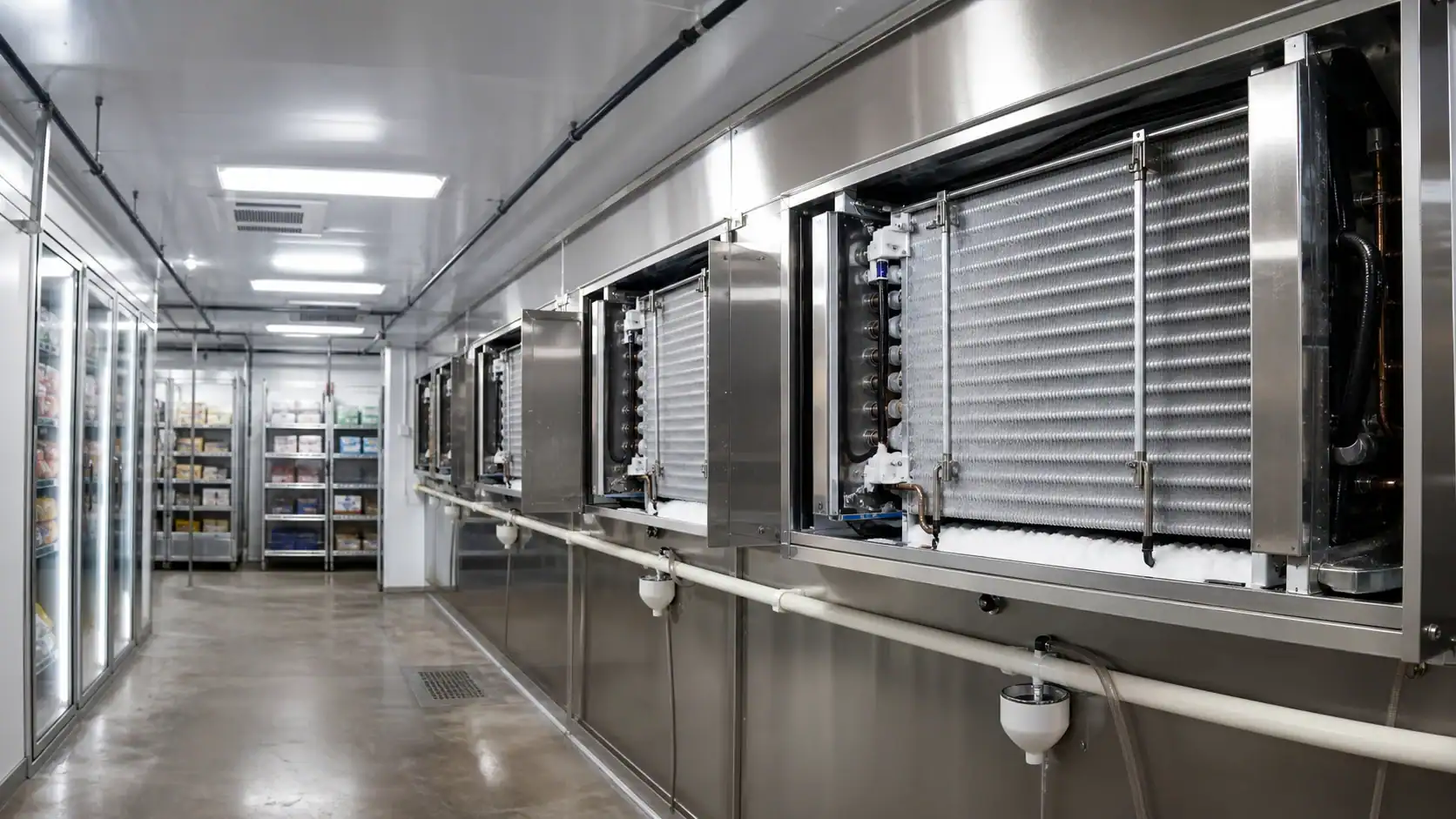
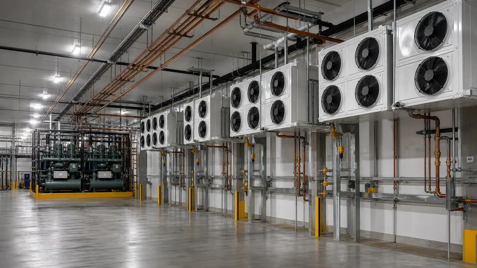
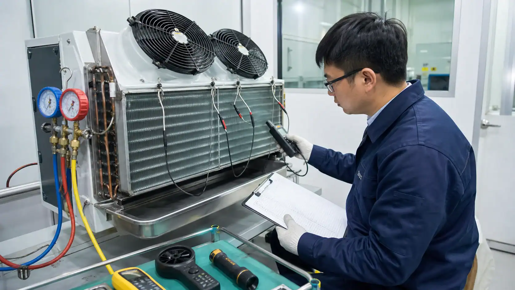
For technical background, compare the commercial guidance in the ASHRAE Handbook retail food store refrigeration chapter with Danfoss guidance on adaptive defrost and hot-gas defrost. These sources describe general methods. The final heater, valve, pressure, and control values still need to be verified for the complete system and applicable code.
Frequently asked questions
What are the three main refrigeration defrost methods?
The common commercial methods are off-cycle or air defrost, electric defrost, and hot-gas defrost. Off-cycle uses available room heat, electric defrost uses resistive heaters, and hot gas uses condensing refrigerant vapor inside the evaporator. Air, water, and other specialized arrangements may be used in selected equipment, but the coil, controls, and drainage still need a complete system review.
When is off-cycle defrost suitable?
Off-cycle defrost is usually the first option for medium-temperature rooms and cases where the evaporator can warm enough to melt frost within the allowed recovery time. It is not a reliable choice for a deep-freeze coil that remains far below freezing. Confirm the room temperature, humidity, frost load, drainage, and recovery test before approving it.
Is electric defrost better than hot-gas defrost?
Neither method is universally better. Electric defrost is often easier to package, control, and service on small or medium systems, while hot gas can be attractive for larger plants with repeated heavy defrost and limited electrical capacity. Compare heater energy, peak demand, valve and piping cost, service skill, and total lifecycle cost.
How should electric defrost be terminated?
Use a coil temperature signal or another validated condition to end the heat cycle, with a maximum-time limit and high-limit safety protection. The sensor must represent the coldest or most frost-prone part of the coil. After heater shutdown, keep fans off long enough for meltwater to drain before restarting airflow.
What causes a refrigeration coil to refreeze after defrost?
Common causes include an incomplete heat cycle, a poorly placed termination sensor, excessive door infiltration, inadequate drain-pan heat, a blocked drain, fan restart before the drip period ends, or an operating condition that is colder than the original design. Check frost pattern, sensor position, drainage, controls, and actual room humidity instead of simply increasing the timer.
What should an OEM include in a refrigeration defrost RFQ?
Include room and evaporating temperatures, refrigerant and design pressure, capacity, coil dimensions, fin spacing, airflow, frost exposure, defrost method, heater or hot-gas requirements, sensor and thermostat locations, drain-pan and drain-line details, controls interface, sample quantity, forecast volume, and the required inspection or performance test.