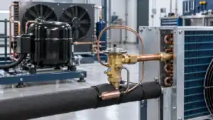
In refrigeration, a condenser rejects heat from high-pressure refrigerant vapor and returns the refrigerant to liquid. This guide organizes 100 condenser types and configurations across heat-rejection method, construction, circuit arrangement, installation, refrigerant, application, materials, and controls. The right choice depends on heat-rejection duty, design ambient, water availability and quality, footprint, noise, service access, refrigerant, and the information available for a reliable quote.
Quick answer: what does a condenser do?
A condenser is the heat-rejection side of a vapor-compression refrigeration system. Discharge gas leaves the compressor hot and at high pressure. In the condenser, heat moves through a coil, tube bundle, plate pack, or another heat-transfer surface to air, water, or a spray-water/air combination. The refrigerant desuperheats, condenses, and leaves as a high-pressure liquid that can feed the expansion device. This is different from an evaporator, which absorbs heat on the low-pressure side.
This guide is written for engineers, OEM buyers, contractors, distributors, and maintenance teams comparing industrial or commercial refrigeration condensers. The 100 entries are a practical taxonomy: some are heat-rejection families, while others are legitimate construction, circuit, installation, refrigerant, application, material, or control configurations. They are not 100 unrelated thermodynamic principles. Separating these dimensions helps a buyer ask for the right product instead of treating every “condenser” as the same unit.
Key takeaways:
- Air-cooled condensers use ambient air and are often the simplest option where water is scarce or water treatment is undesirable.
- Water-cooled condensers can hold a stable condensing condition when a suitable water loop, tower, or fluid cooler is available.
- Evaporative condensers use a wetted air path to improve heat rejection, but water treatment, drift control, freeze protection, and access must be planned.
- Fin-and-tube, shell-and-tube, plate, and microchannel describe construction and flow arrangement; they do not replace the duty and site data needed for selection.
| Condenser family | Heat sink | Best fit | Main trade-off |
|---|---|---|---|
| Air-cooled | Ambient air across a finned coil | Outdoor packages, remote racks, water-limited sites | Capacity and condensing temperature follow ambient and coil cleanliness |
| Water-cooled | Cooling water or treated process water | Plants with a reliable water loop or tower | Pumping, water quality, fouling, and water-side maintenance |
| Evaporative | Air plus evaporating spray water | High heat rejection with a compact outdoor footprint | Water treatment, drift, plume, freeze and service requirements |
| Hybrid or remote | Selected air/water modes or a separated heat-rejection location | Sites balancing noise, space, seasonal operation, or redundancy | More controls, valves, installation coordination, and commissioning detail |
How to narrow 100 condenser configurations
Use the taxonomy in five passes instead of treating all 100 labels as competing products:
- Set the heat sink and design point. Decide whether the site can reliably provide ambient air, treated water, tower water, spray water, or a hybrid path. Record the design ambient or entering water condition, heat-rejection duty, condensing target, and allowable approach temperature.
- Choose the heat-transfer construction. Match fin-and-tube, wire-and-tube, shell-and-tube, plate, coaxial, or microchannel construction to the refrigerant, fluid chemistry, fouling risk, cleaning method, pressure rating, and available footprint.
- Define refrigerant and circuiting. State the refrigerant, mass flow, pressure envelope, oil-return expectation, circuit count, pass arrangement, subcooling target, and part-load operating range before asking for a performance selection.
- Lock the package and airflow. Confirm rooftop, wall, skid, rack, remote, side-discharge, top-discharge, axial-fan, centrifugal-fan, EC-fan, or V-bank requirements together with sound, wind, snow, service, lifting, and electrical constraints.
- Write the RFQ around proof. Ask for a selection sheet, circuiting drawing, fan or pump curve, pressure-drop calculation, materials and coating schedule, test record, controls sequence, packaging details, and the exact items included in the quote.
For a custom condenser coil or heat-exchanger review, send the refrigerant, heat-rejection duty, design ambient or entering-water condition, dimensions, connections, and material exposure through Domi’s contact page.
100 types and configurations of condensers
Use this list as a naming and RFQ checklist. A project specification normally combines several entries, for example “an induced-draft air-cooled, microchannel, multi-circuit, rooftop condenser for R-513A” rather than selecting one label in isolation.
1-10: Heat-rejection families
- Air-cooled condenser: This condenser rejects refrigerant heat directly to ambient air through a finned coil and fans or natural airflow. It suits sites without a reliable condenser-water loop, but the selection must state design ambient, airflow, fin spacing, corrosion exposure, sound limit, and coil-cleaning access.
- Forced-draft air-cooled condenser: Fans mounted upstream push air through the coil, making the air path easy to understand and package. Specify fan static pressure, guards, motor service space, coil face velocity, and how the upstream fan section will be protected from dust, snow, and recirculated hot air.
- Induced-draft air-cooled condenser: Fans downstream pull air across the coil and discharge it away from the heat-transfer surface. This arrangement can reduce hot-air recirculation and improve discharge control, but the RFQ should define fan discharge clearance, service access, vibration isolation, and the required turndown range.
- Natural-convection air condenser: Buoyancy moves air across the condenser without a mechanical fan. It is quiet and simple for small duties or appliance-style equipment, but it needs generous surface area and a clear vertical air path; confirm the worst ambient condition instead of using a fan-cooled rating.
- Water-cooled condenser: Refrigerant heat passes into a water or treated-fluid circuit through tubes, plates, or coaxial passages. This can provide a stable heat sink where a plant loop or tower exists, while the purchase specification must include entering and leaving temperatures, flow, pressure drop, chemistry, filtration, and cleanability.
- Open-loop water-cooled condenser: The condenser uses once-through utility water or tower water that leaves the equipment after absorbing heat. It can be straightforward to control, but scale, corrosion, discharge rules, and water availability are critical; define treatment ownership, strainers, allowable fouling, and local discharge requirements.
- Closed-loop water-cooled condenser: A recirculating loop returns treated water or glycol mixture to a tower, dry cooler, or fluid cooler. The closed circuit reduces exposure to uncontrolled make-up water, but the design still needs expansion volume, pump duty, freeze protection, fluid concentration, air removal, and a documented water-quality plan.
- Evaporative condenser: Spray water wets the heat-transfer surface while moving air removes heat through evaporation. This format can deliver strong heat rejection in a compact outdoor package, but the owner must budget for water treatment, bleed or blowdown, drift control, basin cleaning, freeze protection, plume review, and safe access.
- Hybrid dry/wet condenser: Dry air cooling handles normal operation while an adiabatic or wetted mode assists during demanding conditions. It is useful when the project wants lower annual water use without giving up peak heat-rejection capacity; define mode-change logic, water quality, controls, alarms, and seasonal commissioning.
- Remote condenser: The heat-rejection package is installed away from the compressor, receiver, or conditioned space. Remote placement can move heat and fan noise outdoors, but long liquid and discharge lines introduce routing, oil return, elevation, receiver, insulation, valve, and commissioning requirements that belong on the equipment drawing.
11-20: Core heat-transfer constructions
- Fin-and-tube condenser coil: Round copper or aluminum tubes carry refrigerant through a fin pack that enlarges the air-side surface. It is a flexible industrial coil format, so the RFQ should specify tube material, circuiting, fin spacing, headers, coating, connection orientation, design airflow, and the cleaning method for the actual site.
- Wire-and-tube condenser: A tube is bonded or welded to a wire grid to create an economical air-side surface with open passages. It is common in compact equipment, but buyers should check tube diameter, wire spacing, coating, weld quality, airflow obstruction, and whether the open frame can be cleaned without damaging the refrigerant circuit.
- Tube-on-plate condenser: Tubing is bonded to or embedded against a flat plate, allowing heat to spread across the plate before reaching air or a cabinet surface. It works for static or low-airflow applications, and the design review should cover contact quality, plate flatness, thermal expansion, mounting, frost or dirt exposure, and replacement access.
- Shell-and-tube condenser: One fluid travels through tubes while the other occupies the shell side around a baffled tube bundle. It is a serviceable choice for water-cooled duties, but tube material, pass arrangement, baffle spacing, removable head, pressure rating, fouling allowance, cleaning method, and nozzle orientation must be agreed before fabrication.
- Flooded shell-and-tube condenser: Refrigerant floods the shell side so the tube bundle remains wetted while water flows through the tubes. This can provide effective heat transfer, but liquid level, oil return, vessel volume, relief protection, refrigerant charge, and control of the liquid outlet need a full system review rather than a coil-only quote.
- Direct-expansion shell-and-tube condenser: Refrigerant enters the selected flow path and condenses progressively instead of flooding the entire shell. The design emphasizes distribution, pressure drop, outlet quality, subcooling, and oil movement; specify the refrigerant, mass flow, entering water condition, pass arrangement, and allowable approach temperature.
- Brazed-plate condenser: Corrugated plates are brazed together to form compact alternating channels with no field-openable gasket joint. It offers a small footprint, but fluid cleanliness, refrigerant compatibility, pressure rating, freeze protection, approach temperature, and replacement strategy matter because internal cleaning and repair are limited.
- Gasketed-plate condenser: A bolted plate pack uses replaceable gaskets to separate refrigerant and water channels. It is attractive when the service team needs to open and inspect the exchanger, while gasket material, tightening pattern, plate metallurgy, fluid chemistry, leak testing, spare-gasket availability, and reassembly training should be documented.
- Welded-plate condenser: Plates or plate cassettes are welded to reduce gasketed joints and support demanding pressure or fluid conditions. The trade-off is limited field access for internal cleaning, so specify weld procedure, non-destructive testing, pressure test, corrosion allowance, fluid filtration, and the approved replacement or repair route.
- Microchannel condenser: Flat multi-port tubes and louvered fins create a compact air-side exchanger with headers distributing refrigerant across many small passages. Review header design, circuit balance, allowable pressure drop, fin and tube corrosion, cleaning tools, joining quality, and the practical field-repair method before choosing it for a harsh site.
21-30: Circuit and flow arrangements
- Single-circuit condenser: One continuous refrigerant circuit serves the entire coil or exchanger. It simplifies piping and controls for modest duties, but the selection must check pressure drop, refrigerant distribution, start-up behavior, and what happens if a single circuit becomes fouled or blocked.
- Multi-circuit condenser: Several refrigerant circuits divide the heat-transfer surface to handle larger capacity or different operating stages. Circuit count changes header design, refrigerant distribution, oil return, and service isolation, so request a circuiting drawing, connection schedule, test sequence, and performance at part load.
- Parallel-circuit condenser: Parallel paths share refrigerant flow and discharge heat across a bank. Correct header sizing and equal distribution are essential; ask for circuit balance, pressure-drop calculation, outlet subcooling, and the control sequence that prevents one branch from starving while another carries excess liquid.
- Split-circuit condenser: The coil is divided into independently controllable sections, often for capacity staging, redundancy, or separate refrigerant streams. Define which circuit operates first, how isolation valves and receivers are arranged, how unused sections are protected, and whether each section receives a complete inspection and pressure test.
- Single-pass condenser: The cooling fluid crosses the heat-transfer surface once before leaving. It can reduce piping complexity and pressure drop, but it may need more surface area; include entering and leaving temperatures, flow rate, approach target, connection orientation, and the available cleaning path.
- Multi-pass condenser: Baffles or circuiting send the cooling fluid through the exchanger more than once to improve temperature approach or package efficiency. Additional passes increase pressure drop and cleaning complexity, so specify pass count, velocity range, pump margin, fouling allowance, and tube-side access.
- Counterflow condenser: Refrigerant and cooling fluid move in opposite directions, maintaining a useful temperature difference along much of the exchanger. It can support a compact design and liquid subcooling, but the drawing must show flow direction, connection locations, control-sensor positions, pressure drop, and freeze or oil-return precautions.
- Crossflow condenser: The two fluids move substantially perpendicular to one another, as in many air-cooled coil arrangements. Crossflow packaging can simplify fans and headers, yet the selection still needs face velocity, circuiting, air bypass, approach temperature, and coil-cleaning clearances tied to the installation.
- Serpentine-circuit condenser: A continuous serpentine path winds through the coil or tube bundle to create a long heat-transfer route. It can be useful for compact equipment, but pressure drop, oil movement, manufacturing bend radius, vibration, and service replacement must be checked rather than inferred from the outside dimensions.
- Desuperheater-plus-condenser arrangement: A dedicated upstream section removes discharge superheat before the main condensing surface handles phase change. This can support heat recovery or tighter temperature control, but the design must define section duties, refrigerant pressure drop, drain or receiver behavior, controls, insulation, and test points.
31-40: Installation and package formats
- Complete condensing unit: A packaged assembly may combine compressor, condenser, receiver, controls, pressure protection, and service valves. The phrase is not universal, so an RFQ must state exactly which components, wiring, factory charge, documentation, and commissioning responsibilities are included instead of assuming “unit” means a complete system.
- Remote condensing unit: The compressor and controls are packaged together while the condenser or heat-rejection section is installed elsewhere. Confirm line lengths, elevation, oil return, receiver sizing, liquid-line subcooling, field wiring, communication, isolation, and the service envelope at both locations.
- Rooftop condenser: The condenser is designed for roof loading, weather exposure, wind, lifting, and drainage. The package should show curb or support details, vibration isolation, access routes, corrosion protection, fan discharge clearance, electrical disconnects, and the maintenance plan for cleaning at elevation.
- Side-discharge condenser: Air leaves through the side of the package, which can suit narrow roof lanes or wall-adjacent installations. Verify side clearance, recirculation risk, fan guard access, sound direction, service panel swing, coil face orientation, and whether neighboring equipment will obstruct the discharge plume.
- Top-discharge condenser: Fans discharge warm air vertically above the coil, helping keep exhaust away from the intake when roof clearance is available. Check vertical clearance, wind effects, snow or rain entry, fan replacement path, service platform, and the possibility of discharge recirculation under canopies.
- Wall-mounted condenser: The unit hangs on a wall bracket or structural frame to save floor space. Confirm bracket loads, wall material, vibration transfer, coil cleaning access, drain routing, fan clearance, lifting method, and whether the wall can support the package during seismic or high-wind events.
- Skid-mounted condenser: Heat-rejection equipment, pumps, valves, controls, and structural supports arrive on a common skid. Skids simplify factory assembly but require clear lifting points, center of gravity, anchor pattern, piping limits, electrical interfaces, field-access zones, and a responsibility matrix for interconnecting services.
- Rack-mounted condenser: Multiple condenser sections or modules are installed on a common refrigeration rack or support frame. The rack design must coordinate headers, vibration, isolation, fan staging, receiver and oil management, service clearance, module replacement, and future capacity additions without blocking the existing airflow path.
- Containerized condenser package: The condenser and supporting equipment are arranged inside or on a transportable enclosure. Review ventilation, heat rejection from the enclosure, lifting and transport restraints, fire and refrigerant safety, access doors, noise, drainage, controls, and the site connection list before accepting a containerized layout.
- Packaged outdoor condenser: The complete heat-rejection assembly is weatherized for outdoor installation with enclosure, coating, guards, and controls. Specify ambient range, rain and snow exposure, UV resistance, salt or chemical exposure, electrical rating, freeze strategy, sound limit, and the inspection points accessible without dismantling panels.
41-50: Air path and fan configurations
- Axial-fan condenser: Axial fans move a large volume of air through a relatively open coil with efficient straight-through flow. They suit outdoor heat-rejection banks, but the design should state fan diameter, speed, static-pressure capability, guard spacing, sound, vibration, and the control method used during low ambient operation.
- Centrifugal-fan condenser: A centrifugal fan develops more static pressure and can overcome duct or louver resistance. It is useful where the discharge must be routed, but the RFQ must include duct pressure, fan curve, motor service, belt or direct-drive arrangement, noise treatment, access, and condensate or rain management.
- EC-fan condenser: Electronically commutated motors combine efficient motors with integrated speed control and often allow precise fan staging. Confirm voltage, communication protocol, fault output, minimum speed, harmonics, replacement availability, and whether the controls can maintain stable head pressure without hunting.
- Variable-frequency-drive fan condenser: A conventional motor is controlled through a variable-frequency drive to match airflow to load and ambient conditions. Specify motor compatibility, drive enclosure, bypass or failure mode, minimum safe speed, electromagnetic compatibility, ramp time, service disconnect, and the pressure-control signal used by the refrigeration system.
- Single-fan condenser: One fan serves the entire heat-transfer surface, reducing component count and simplifying controls. The trade-off is limited redundancy; evaluate the effect of one fan fault, access for replacement, airflow uniformity, vibration, minimum turndown, and whether the coil can safely carry the load during a short service interruption.
- Multi-fan condenser array: Several fans divide the coil into controllable zones and allow staged capacity. This can improve turndown and maintenance flexibility, but fan spacing, header circuiting, control sequencing, sound interaction, spare strategy, and the airflow pattern between adjacent fans should be verified at both full and partial load.
- Push-through forced-draft condenser: Fans push air into the coil from the inlet side, so the fan section is easy to reach before the coil. Define inlet filtration, fan guard, air distribution, coil access behind the fans, recirculation control, and the pressure drop allowed through louvers, screens, and weather hoods.
- Pull-through induced-draft condenser: Fans pull air through the coil and discharge it after the heat-transfer surface. The arrangement can reduce inlet-side bypass and help collect a uniform air stream, while the design must allow safe fan access, discharge clearance, vibration isolation, and protection from hot-air recirculation.
- V-bank condenser: Two or more coil faces form a V shape around a central or shared fan arrangement. The geometry packs surface area into a compact footprint, but the selection should check coil-face balance, header access, fan service, snow and debris accumulation, air bypass at the apex, and lifting or replacement clearances.
- A-frame condenser: Coil panels form an A shape with fans or an air path arranged around the peak. A-frames are useful for large outdoor banks, but the structure needs clear drainage, support and wind calculations, coil cleaning access, balanced circuiting, fan replacement space, and a safe walkway or service platform.
51-60: Water-side constructions and loops
- Single-pass shell-and-tube water condenser: Water enters one end of the tube bundle and leaves the other after one pass. It is simple to pipe and clean, but it may require more surface area; specify water flow, tube velocity, pressure drop, fouling allowance, tube material, and the available flushing or mechanical-cleaning method.
- Two-pass shell-and-tube water condenser: A divider sends water through the tube bundle twice before it exits, increasing contact time within a compact shell. The additional pass changes pressure drop and connection placement, so confirm pass partition, flow direction, pump margin, tube-side velocity, venting, drainage, and access for inspection.
- Multi-pass shell-and-tube water condenser: Three or more passes trade higher fluid velocity and heat-transfer potential for added pressure drop and more complex heads. Select it only after checking pump energy, water quality, cleaning tools, tube vibration, pass partition integrity, and the operating condition at reduced load.
- Coaxial water-cooled condenser: One tube is arranged inside another, creating a compact annular flow path for refrigerant and water. It can suit smaller packages or limited footprints, but the quote should identify flow direction, tube materials, pressure ratings, freeze protection, fouling tolerance, and how the concentric assembly will be replaced.
- Tube-in-tube condenser: Refrigerant and cooling fluid travel through separate concentric passages, often with a straightforward counterflow path. It is compact and easy to describe, but surface area, pressure drop, concentricity, brazed or welded joints, access for flushing, and protection from trapped liquid need to be documented.
- Brazed-plate water condenser: A brazed plate pack transfers refrigerant heat to water through many narrow channels. It offers a small footprint but is sensitive to dirty water and freeze damage; specify filtration, water chemistry, approach temperature, pressure rating, installation orientation, and a practical replacement plan.
- Gasketed-plate water condenser: A bolted plate pack lets technicians open the water side for cleaning and gasket replacement. It is service-friendly when the plant has trained personnel, so include gasket compound, plate material, tightening dimension, leak-test method, spare parts, and the chemical limits of the treatment program.
- Welded-plate water condenser: Welded channels reduce gasket exposure and can handle selected pressure or fluid combinations. The exchanger is less accessible for field opening, which makes filtration, weld inspection, pressure testing, corrosion allowance, drainability, and a replacement or factory-repair route particularly important.
- Open cooling-tower water condenser: Tower water contacts ambient air and returns to the condenser after rejecting heat through evaporation. The condenser selection must be coordinated with tower approach, fan and pump controls, cycles of concentration, filtration, blowdown, drift, legionella-management responsibilities, and seasonal freeze protection.
- Closed-loop glycol-water condenser: A water and glycol mixture circulates in a sealed secondary loop connected to a dry cooler, tower, or fluid cooler. Specify concentration, viscosity, freeze point, pump head, expansion vessel, inhibitor package, fluid compatibility, heat-exchanger approach, and the fill and maintenance procedure.
61-70: Evaporative and hybrid configurations
- Forced-draft evaporative condenser: Fans push air and spray water through the heat-rejection section from the inlet side. This can keep fan components accessible, but the design must control nozzle distribution, basin carryover, drift, air pressure drop, spray-pump duty, water treatment, and safe cleaning around wet electrical equipment.
- Induced-draft evaporative condenser: Fans pull air through the wetted coil or tube bundle and discharge the warm, moist air above the unit. Review plume behavior, fan and motor access, drift eliminator performance, spray coverage, basin level control, freeze protection, and the clearance required to avoid recirculating saturated air.
- Crossflow evaporative condenser: Air crosses the spray-wetted heat-transfer surface in a direction substantially perpendicular to the refrigerant or water path. The arrangement can simplify access to spray components, while nozzle layout, air distribution, drift control, water level, fill or coil inspection, and cleaning chemistry remain key design inputs.
- Counterflow evaporative condenser: Air moves opposite the direction of falling spray water, creating a longer contact path between air and water. It can support a compact package, but buyers should confirm fan pressure, eliminator access, spray uniformity, basin cleanliness, water treatment, plume, noise, and low-temperature operation.
- Spray-coil evaporative condenser: Water is sprayed directly over an external coil or tube bundle while fans move air across the wetted surface. The RFQ should detail nozzle type, spray pattern, filtration, scaling allowance, coil coating, pump redundancy, drain and blowdown, and how the spray system will be isolated during service.
- Adiabatic pre-cooler condenser: Dry air passes through a wetted pad or atomized-water stage before reaching an air-cooled coil. It can reduce entering-air temperature without continuously wetting the refrigerant coil, but water quality, pad replacement, droplet carryover, controls, freeze protection, and the dry-mode capacity must be stated.
- Dry-mode/wet-mode hybrid condenser: One package supports dry operation and a wetted assist mode selected by ambient or head-pressure control. The specification should state the changeover threshold, water enable conditions, ramp sequence, alarm behavior, drain-down, freeze protection, and the performance and sound expectation in both modes.
- Parallel dry/wet condenser bank: Separate dry and evaporative banks operate in parallel and share the refrigeration duty. This can provide redundancy or flexible water use, but header sizing, valve isolation, receiver behavior, control priority, water-treatment scope, fan staging, and the consequences of taking one bank offline must be documented.
- Seasonal wet-operation condenser: The unit is dry for much of the year and enables spray water only during selected high-ambient periods. Seasonal operation reduces water use, but it requires a start-up inspection, nozzle and basin preservation, drain-down, freeze protection, seasonal valve exercise, water-quality verification, and a clear operator checklist.
- Plume-controlled evaporative condenser: The package includes airflow, heat-recovery, dry-section, or control measures intended to reduce visible moisture discharge. Plume behavior depends on ambient humidity and load, so do not promise zero plume; specify the site expectation, weather envelope, control sequence, drift limit, and acceptance method.
71-80: Refrigerant-specific condenser designs
- Ammonia (R-717) condenser: Ammonia systems require materials, pressure protection, oil management, and safety procedures suited to ammonia service. The condenser specification should state design pressure, relief routing, welding and inspection requirements, refrigerant charge strategy, detector and ventilation interfaces, and the plant’s authorized service practices.
- Subcritical carbon-dioxide (R-744) condenser: In subcritical CO2 operation, the refrigerant condenses below its critical point and operates at comparatively high pressure. Confirm pressure rating, relief devices, tube or plate material, control response, standstill pressure strategy, brazing or welding qualification, and the transition conditions if the system can operate in another mode.
- Propane (R-290) condenser: Propane is a flammable refrigerant, so the condenser is selected with charge, electrical classification, ventilation, ignition control, and service procedures in mind. Specify pressure, leak testing, component compatibility, hazardous-area requirements, charge limitation, factory handling, and the approved field-service boundary.
- Isobutane (R-600a) condenser: Isobutane condensers are used in selected compact or appliance systems where low charge and flammability controls are important. Review tube volume, circuiting, pressure, joining method, leak detection, ventilation, electrical components, service labeling, and the equipment standard governing the complete product.
- R-134a condenser: R-134a condenser design is common in legacy and selected medium-temperature applications, but the operating envelope and future refrigerant strategy still matter. Specify capacity, condensing temperature, subcooling, material compatibility, oil return, pressure drop, and whether the replacement must match an existing coil footprint.
- R-404A condenser: R-404A systems often serve low-temperature commercial or industrial loads and may impose demanding discharge and ambient conditions. The condenser selection should identify the actual replacement refrigerant plan, design pressure, fan control, receiver arrangement, subcooling target, material condition, and environmental or regulatory constraints.
- R-407C condenser: R-407C is a zeotropic blend with temperature glide, so circuiting and measurement points need careful interpretation. Request bubble and dew references, design condensing condition, pressure-drop limit, liquid-line arrangement, service charging procedure, and the sensor locations used to verify outlet subcooling.
- R-410A condenser: R-410A operates at higher pressure than many older HFC systems, so the condenser, headers, joints, relief protection, and service tools must be rated accordingly. Confirm coil design pressure, test pressure, connection size, fan control, replacement dimensions, and the equipment standard used for approval.
- R-448A/R-449A condenser: These retrofit-oriented blends can change capacity, mass flow, glide, and pressure relationship compared with older refrigerants. A condenser review should compare the actual compressor and expansion-device envelope, circuiting, pressure drop, outlet measurement method, oil compatibility, and available subcooling under the site ambient.
- R-513A condenser: R-513A can be selected in certain lower-global-warming-potential replacement strategies where equipment compatibility is confirmed. Do not infer a drop-in result from the name alone; document capacity, glide, pressure, compressor approval, material compatibility, relief settings, and the test points used for the final selection.
81-90: Application-specific condensers
- Commercial refrigeration condenser: This condenser serves display cases, reach-ins, walk-ins, or other commercial loads with frequent cycling and service access needs. The specification should include ambient, sound, cleaning frequency, fan staging, defrost interaction, corrosion exposure, connection layout, and whether the buyer wants a coil only or a complete condensing unit.
- Industrial refrigeration condenser: Industrial equipment is selected for larger duty, longer operating hours, plant integration, and formal inspection. Define refrigerant, capacity, design ambient or water condition, redundancy, pressure class, materials, control interfaces, lifting, test documentation, and the maintenance window available to the plant team.
- Cold-storage condenser: Cold-storage systems often operate continuously and see dusty yards, washdown, or low ambient conditions. Match the condenser to the room temperature, pull-down duty, head-pressure control, defrost schedule, coil cleaning, fan cycling, corrosion exposure, winter operation, and the available roof or yard footprint.
- Blast-freezer condenser: Blast freezers create high and rapidly changing refrigeration demand during pull-down. The condenser should be checked for peak heat rejection, fan or water control response, oil and receiver behavior, defrost recovery, low-load stability, service access, and the short-term duty profile rather than only the holding load.
- Food-processing condenser: Food plants may combine high duty with washdown, sanitation chemicals, stainless requirements, and strict access rules. Specify corrosion protection, hygienic clearance, drainage, coating compatibility, sound, pressure testing, materials traceability, and whether the condenser must remain accessible while production lines operate.
- Beverage-refrigeration condenser: Beverage equipment may have compact cabinets, high ambient exposure, frequent door opening, and cleanliness constraints. Confirm coil geometry, fan noise, fin spacing, coating, airflow path, electrical interface, service panel access, and the required recovery after a high-load pull-down or production change.
- Ice-machine condenser: Ice machines can use air, water, or remote heat rejection and often operate with repeated freeze and harvest cycles. The condenser selection should cover peak cycle heat, water quality where applicable, scale control, fan or pump cycling, harvest heat, cleaning access, and the manufacturer’s approved refrigerant and component envelope.
- Supermarket rack condenser: A rack condenser serves multiple compressors and refrigeration circuits with changing load combinations. Review common headers, oil and liquid management, fan staging, floating head-pressure control, circuit isolation, receiver volume, sound, service redundancy, and future rack capacity before selecting the coil or bank.
- Process-chiller condenser: A process chiller condenser must reject heat reliably across a defined production envelope rather than a short comfort-cooling cycle. Provide leaving-fluid temperature, process turndown, ambient or water limits, pump and fan controls, redundancy, fouling allowance, alarms, test points, and the consequences of a condenser trip to production.
- Heat-pump outdoor condenser coil: In heating mode, the outdoor coil acts as a condenser while the refrigeration circuit reverses between modes. The coil therefore needs a design that supports both heat rejection and heat absorption, with attention to defrost, condensate drainage, frost, pressure drop, reversing valves, fin spacing, and coil protection.
91-100: Materials, surface treatment, and control variants
- Copper-tube/aluminum-fin condenser: Copper tubes provide familiar joining and refrigerant compatibility while aluminum fins provide economical air-side surface. Specify tube wall, fin thickness and spacing, circuiting, galvanic protection, coating, brazing or welding quality, cleaning tools, and the expected salt, chemical, or humidity exposure.
- Aluminum microchannel condenser: Flat aluminum multi-port tubes and fins create a compact all-aluminum coil with small passages and integrated headers. The design review should cover corrosion protection, header joining, allowable pressure drop, cleaning pressure, fin damage, refrigerant distribution, and whether the service team can repair or replace the coil.
- Stainless-steel tube condenser: Stainless tubing is selected when water chemistry, hygiene, or chemical exposure makes other tube materials unsuitable. Confirm grade, weld procedure, passivation, chloride limit, thermal conductivity trade-off, pressure rating, inspection method, gasket or dissimilar-metal compatibility, and the cleaning chemicals allowed by the owner.
- Epoxy-coated condenser coil: An epoxy coating adds a protective barrier for selected corrosive or coastal environments. Coating is not a substitute for correct material selection, so specify surface preparation, coverage, cure, thickness range, connection masking, thermal impact, repair kit, inspection record, and warranty boundaries.
- E-coat-protected condenser: Electrodeposition coating can provide more uniform coverage around coil geometry than a simple spray coat. Ask for pretreatment, coating system, cure validation, tube and fin compatibility, cut-edge treatment, pressure-test timing, field touch-up method, and the exposure category used for the corrosion decision.
- Hydrophilic-fin condenser: Hydrophilic fin treatment changes water behavior on the air-side surface and can help drainage or reduce persistent droplets in selected applications. Confirm coating compatibility, salt and chemical exposure, cleaning method, frost behavior, fin spacing, thermal effect, and whether the finish is required on every surface or only the air-entry face.
- Marine-corrosion-resistant condenser: Marine or coastal service exposes the coil and frame to salt aerosol, humidity, wind, and difficult cleaning conditions. A robust specification combines tube and fin material, coating, fasteners, drain design, electrical enclosure, inspection frequency, packaging, and a defined salt-exposure or corrosion-acceptance requirement.
- Heat-recovery condenser: A heat-recovery condenser captures part of the rejected heat for water heating, process preheat, or another useful load before final rejection. Define recovery temperature, simultaneous heating and cooling duty, control priority, pressure drop, sanitary or process-fluid boundary, bypass mode, and what happens when the heat sink is unavailable.
- Electronically controlled condenser: Sensors, electronic valves, fan drives, and a controller regulate condensing pressure, subcooling, water flow, or staged capacity. The project must define sensor locations, setpoint authority, communication protocol, alarm states, manual override, fail-safe behavior, commissioning tools, cybersecurity expectations, and replacement access.
- Redundant condenser bank: Two or more condenser modules share duty so one can continue operating during maintenance or a fault. Redundancy is only meaningful when headers, valves, controls, receiver volume, electrical supply, isolation, and service procedures support it; specify the required standby capacity and the switchover test.
Types of condensers by heat-rejection method
Air-cooled condenser
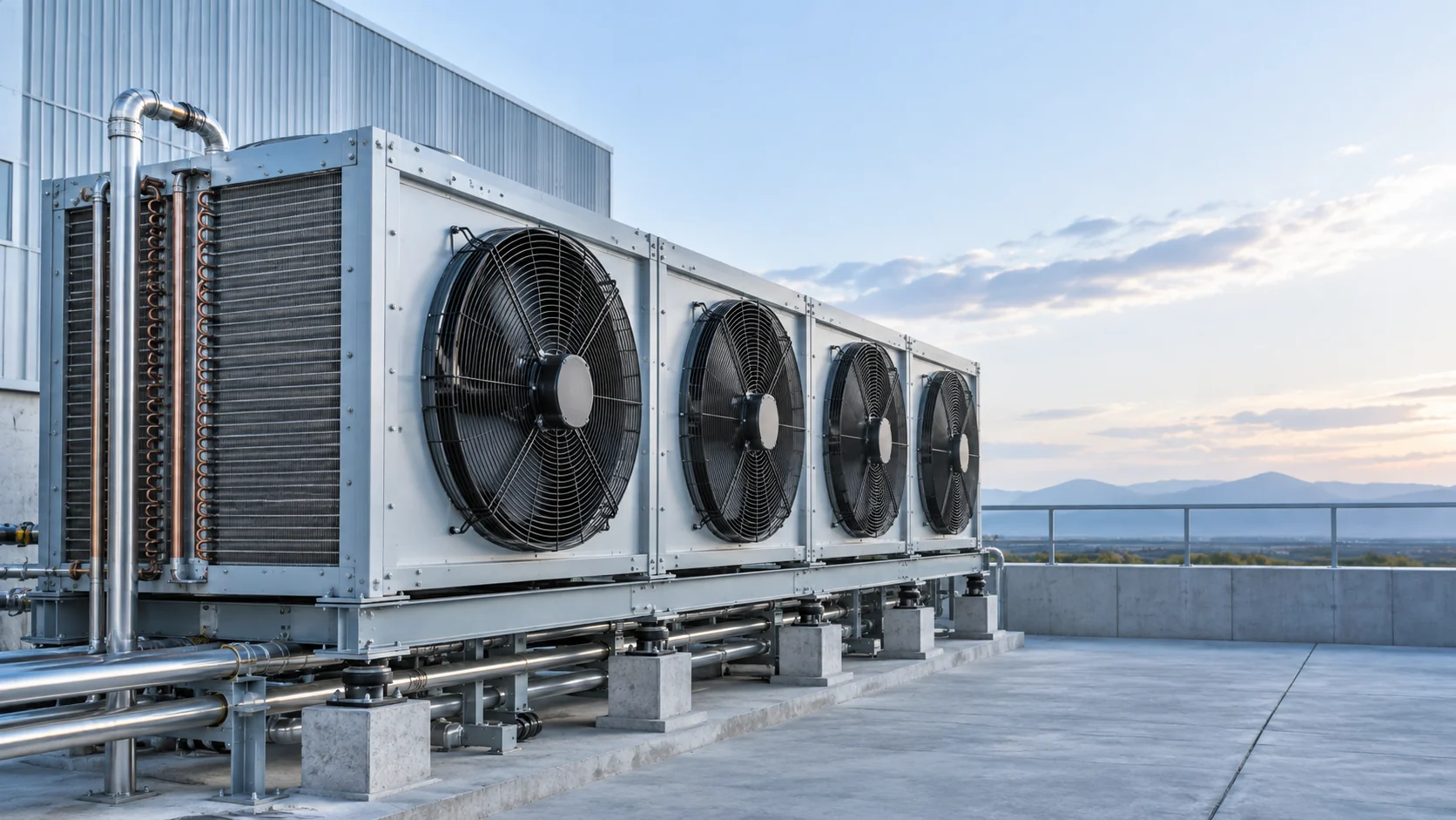
An air-cooled condenser rejects heat through a finned coil and fans. Axial fans move ambient air over the outside of tubes, while the refrigerant condenses inside the circuit. The design is familiar to contractors, does not require a condenser-water loop, and can be packaged as a remote condenser or mounted with a condensing unit. It is commonly considered when water consumption, water treatment, or a cooling tower is not acceptable.
Selection still requires more than a nominal tonnage. Design ambient, entering-air temperature, refrigerant, required subcooling, fan control range, coil face velocity, sound limit, fin spacing, corrosion exposure, and service clearance can change the practical result. A coil that works at a mild design ambient may not provide the same condensing condition at a hot roof or a dusty industrial site.
Water-cooled condenser
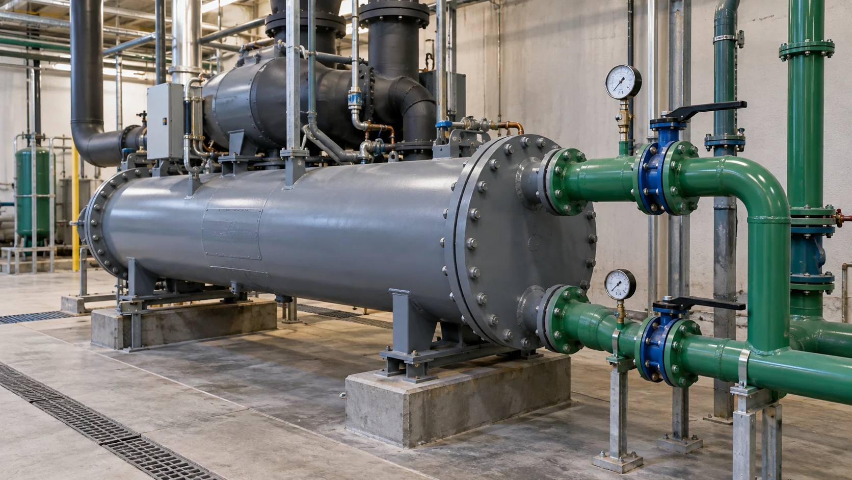
A water-cooled condenser transfers refrigerant heat into a water circuit. Shell-and-tube, brazed-plate, and welded-plate arrangements are common construction choices. The stable water-side temperature can make this approach attractive for process cooling, central plants, and facilities that already have a tower, dry cooler, or treated closed loop.
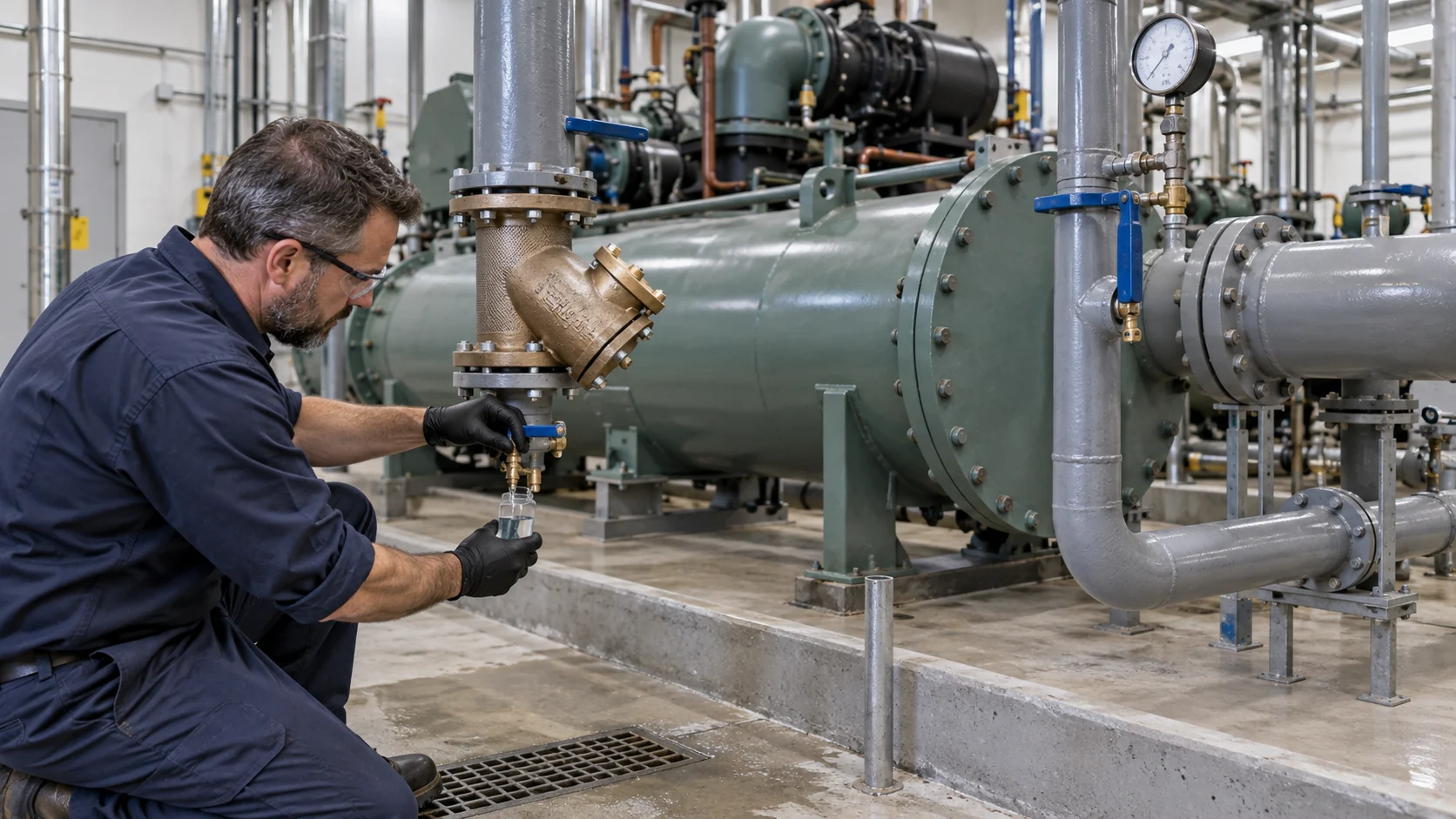
The water side becomes part of the equipment risk. The RFQ should identify entering and leaving water temperatures, design flow, allowable pressure drop, fluid chemistry, filtration, treatment responsibility, and whether the circuit is open or closed. Fouling, scale, corrosion, trapped air, poor flow control, and an undersized pump can reduce heat transfer even when the refrigerant circuit is correct.
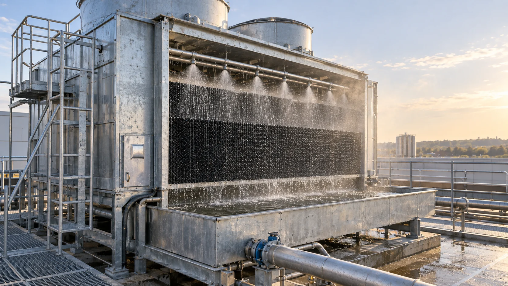
Evaporative condenser
An evaporative condenser sprays water over a heat-transfer surface while fans move air through the wetted path. A portion of the water evaporates and carries away heat, allowing a lower condensing condition than a dry air path in many operating situations. This can make the format useful for large refrigeration duties where roof area, fan power, and design ambient all matter.
Evaporative equipment needs a service plan from the start. Water quality, bleed or blowdown, basin cleaning, spray-nozzle access, drift control, winter operation, freeze protection, plume expectations, and local water rules belong in the project brief. “Compact” does not mean maintenance-free; a neglected spray system can create scale, blocked nozzles, corrosion, or uneven wetting.
Hybrid, remote, and split condenser arrangements
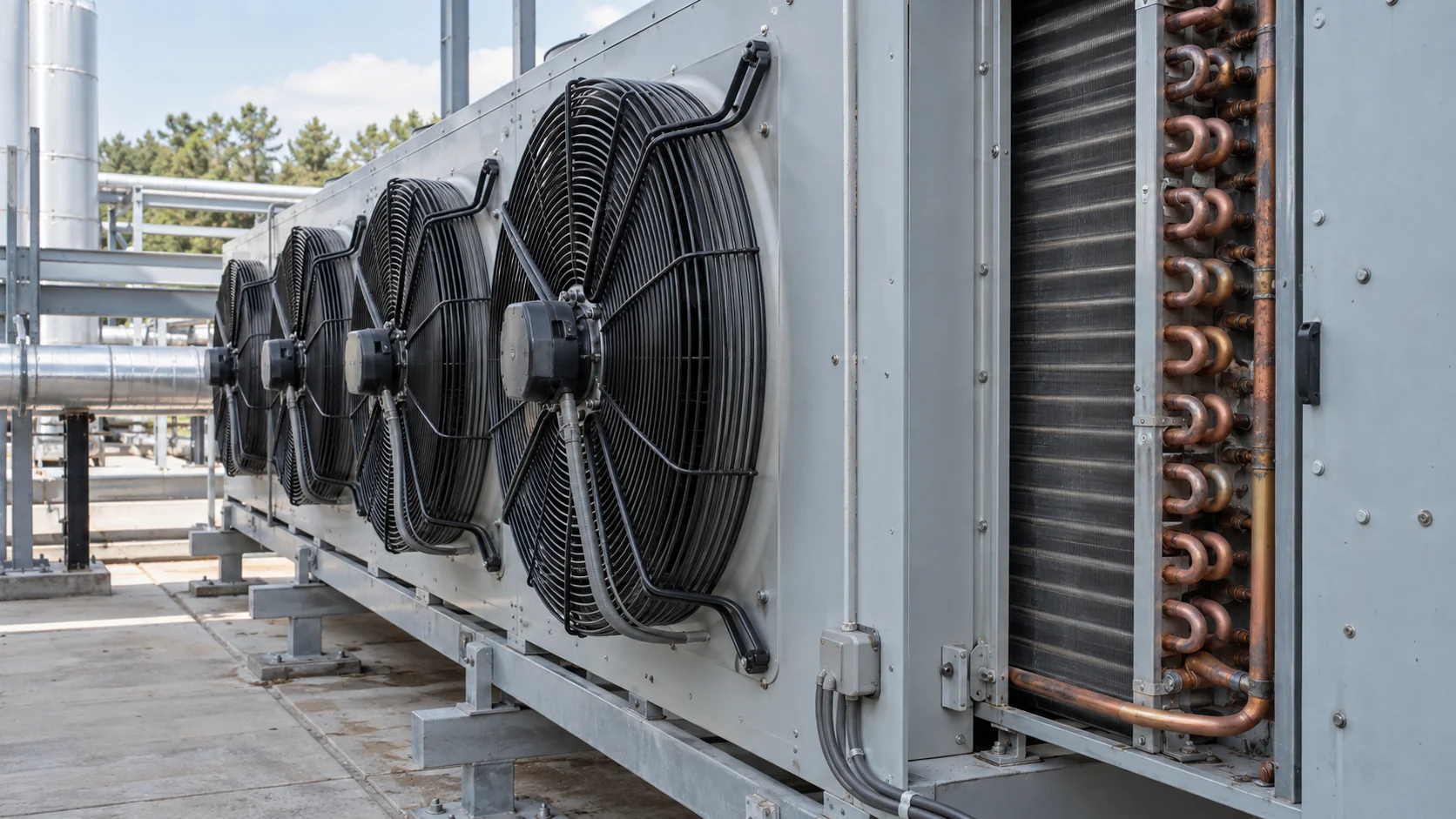
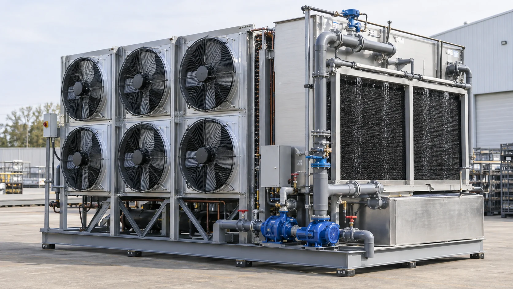
Hybrid systems combine operating modes or separate the heat-rejection package from the compressor and receiver area. A remote air-cooled condenser can move fan noise and heat away from a production room. A hybrid air/water arrangement can use a dry mode during cool weather and a wetted mode during peak conditions, subject to the selected equipment and controls.
These arrangements are specified as a system, not only as a coil. The engineer should define receiver location, liquid-line length, elevation, oil return, fan or pump staging, isolation valves, controls, defrost interactions, and commissioning responsibilities. The layout below illustrates the kind of package-level coordination a buyer should expect in a custom discussion.
Condenser constructions buyers will see in an RFQ
The heat-rejection method answers “where does the heat go?” Construction answers “how does the heat cross the metal?” Both are needed in a purchase specification.
Fin-and-tube condenser coils
Fin-and-tube coils place refrigerant tubes through aluminum or copper fins. The fins enlarge the air-side surface, while circuits and headers distribute refrigerant. Tube diameter, circuit count, fin spacing, material, coating, header arrangement, and connection size should be tied to the refrigerant, duty, airflow, and corrosion environment. Tight fin spacing can improve surface area but may be unsuitable for dusty or lint-heavy applications.
Shell-and-tube condensers
Shell-and-tube equipment routes one fluid through tubes and the other through a shell. Baffles, tube material, pass arrangement, removable heads, and cleanability influence performance and maintenance. A shell-and-tube condenser can be a practical match for water loops and larger duties when the plant can support the water-side service plan.
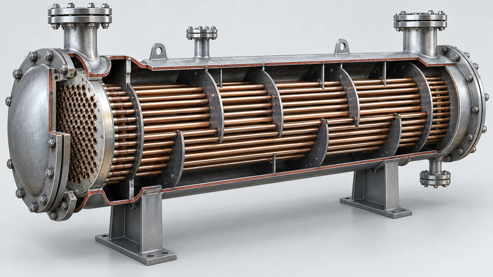
Plate and welded-plate condensers
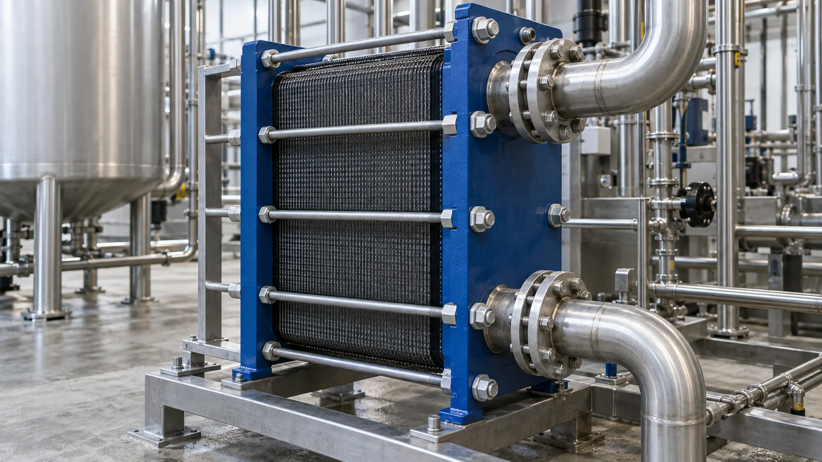
Plate heat exchangers use a compact stack of formed plates to create alternating channels. Gasketed plates can be opened for inspection, while brazed or welded constructions reduce some joints but change service and replacement considerations. Pressure, refrigerant compatibility, fluid cleanliness, approach temperature, pressure drop, and repair method should be confirmed before selecting a plate format.
Microchannel condensers
Microchannel condensers use flat multi-port tubes and fins to create a compact air-side heat exchanger. They can reduce refrigerant volume and package depth, but cleaning technique, header design, brazing or joining quality, repairability, and corrosion protection deserve close review. The correct comparison is the complete coil at the specified airside pressure drop and condensing condition, not a surface-area claim alone.
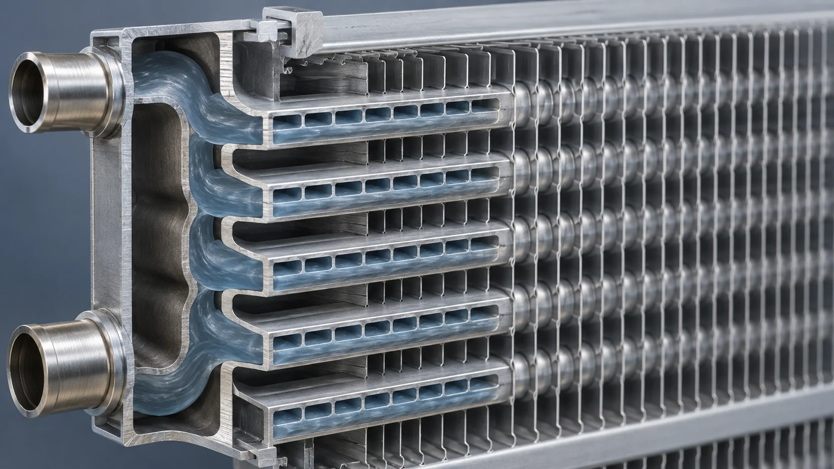
| Construction | Typical heat sink | Strengths | RFQ questions |
|---|---|---|---|
| Fin-and-tube coil | Air | Familiar service, flexible circuits, broad material choices | Refrigerant, circuiting, fin spacing, corrosion, airflow, connection layout |
| Shell-and-tube | Water or process fluid | Robust shell, serviceable tube bundle options | Tube material, passes, water chemistry, fouling allowance, cleanability |
| Plate or welded plate | Water or process fluid | Compact approach and modular surface | Pressure, fluid cleanliness, gasket or weld strategy, pressure drop |
| Microchannel coil | Air | Compact package and low internal volume potential | Header design, cleaning, corrosion, joining, field repair method |
How the condenser fits into the refrigeration cycle
The compressor sends superheated discharge vapor into the condenser. The condenser first removes superheat, then rejects the latent heat needed to change vapor into liquid, and may provide additional subcooling before the liquid line. The expansion device then lowers pressure, and the evaporator absorbs heat before vapor returns to the compressor.
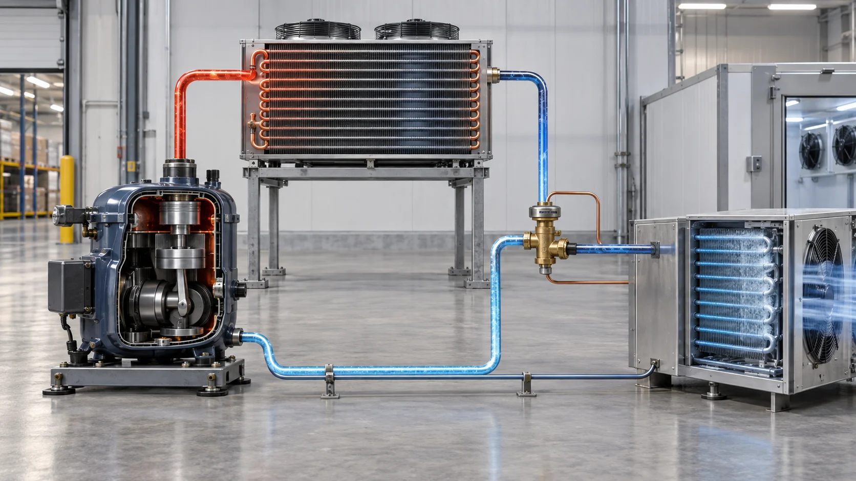
For a project review, trace the full path rather than looking at the condenser in isolation. Confirm refrigerant and oil compatibility, discharge pressure limits, relief protection, liquid-line routing, receiver volume, fan or pump staging, controls, and the operating envelope. The ASHRAE Handbook resources and AHRI standards and certification resources are useful starting points for standards-led design work; the final selection must still follow the applicable equipment documentation and local code.
How to choose a condenser for an industrial project
Start with the heat sink that the site can reliably provide, then test the selection against the operating envelope and the maintenance team’s capability.
- Define the refrigerant, mass flow or capacity, design condensing temperature, required subcooling, and allowable pressure drop.
- Record design ambient or entering-water conditions, including the worst credible seasonal condition rather than an average day.
- Decide whether water use, treatment, plume, fan noise, roof loading, or indoor heat rejection creates a site constraint.
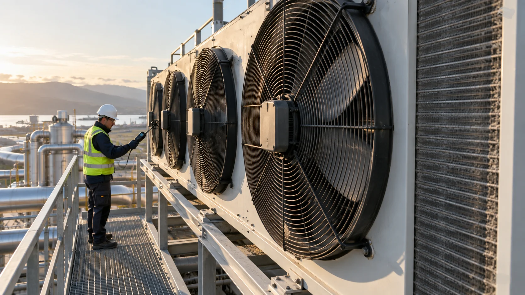
- Reserve access for coil cleaning, tube or plate inspection, spray-nozzle work, filter changes, isolation, lifting, and safe refrigerant service.
- Compare fan power, pump power, water consumption, controls, and expected fouling as operating costs, not only first cost.
- Verify material and coating choices for salt air, chemicals, dust, washdown, or other exposure.
- Ask for a drawing, connection schedule, test method, and inspection record before approving a custom build.
| Selection input | Why it changes the condenser | Evidence to send or request |
|---|---|---|
| Refrigerant and duty | Changes pressure, circuiting, surface area, and safety requirements | Refrigerant, capacity, mass flow, design points, operating envelope |
| Ambient or water condition | Sets the available heat sink and condensing temperature | Design ambient, entering/leaving water, flow, seasonal limits |
| Heat-transfer construction | Changes service method, pressure drop, materials, and package size | Coil or exchanger format, drawing, connections, passes, materials |
| Water quality and treatment | Determines scale, corrosion, fouling, and cleaning burden | Fluid chemistry, filtration, treatment plan, blowdown or closed-loop details |
| Airflow, sound, and site | Governs fan arrangement, face velocity, noise, and access | Fan data, sound limit, installation elevation, clearances, service route |
| Controls and redundancy | Determines staging, turndown, alarms, and recovery after a fault | Sequence of operation, sensors, isolation, standby strategy |
Common condenser mistakes and their consequences
Most condenser problems are selection or installation problems that appear later as high head pressure, poor capacity, nuisance trips, water-side fouling, or difficult service. Use the following checks during design review.
| Common mistake | What it can cause | Better corrective input |
|---|---|---|
| Selecting from nominal capacity only | High condensing temperature at the actual ambient or water condition | Provide design points, refrigerant, subcooling, and pressure-drop limits |
| Treating a condenser coil and a condensing unit as the same item | Missing fan, receiver, controls, or connection responsibilities | State whether the RFQ is for a coil, packaged unit, or complete system |
| Ignoring water quality | Scale, corrosion, blocked passages, and falling heat transfer | Define chemistry, filtration, treatment ownership, and cleanability |
| Using tight air-side fin spacing in a dirty environment | Rapid blockage and rising fan power | Match fin spacing, filtration, access, and cleaning method to the site |
| Leaving no service clearance | Unsafe or incomplete cleaning, inspection, and refrigerant work | Put service envelope and lifting path on the layout drawing |
| Omitting control and redundancy details | Short cycling, unstable head pressure, or a single point of failure | Define staging, sensors, alarms, isolation, and fallback mode |
RFQ checklist and project workflow
Send a concise technical package so a condenser supplier can respond with a comparable design. Include the refrigerant and duty, design ambient or water temperatures, target condensing condition, subcooling, pressure-drop limit, connection sizes and orientation, materials, coating, sound or footprint limits, electrical data, controls, delivery location, quantity, and required documentation.
For a custom coil or exchanger, add a drawing revision, tube and fin material, circuiting preference, test requirement, packaging constraint, sample or prototype need, and whether the supplier must support installation. A good RFQ also names the person who can answer technical questions and the date by which deviations must be reported.
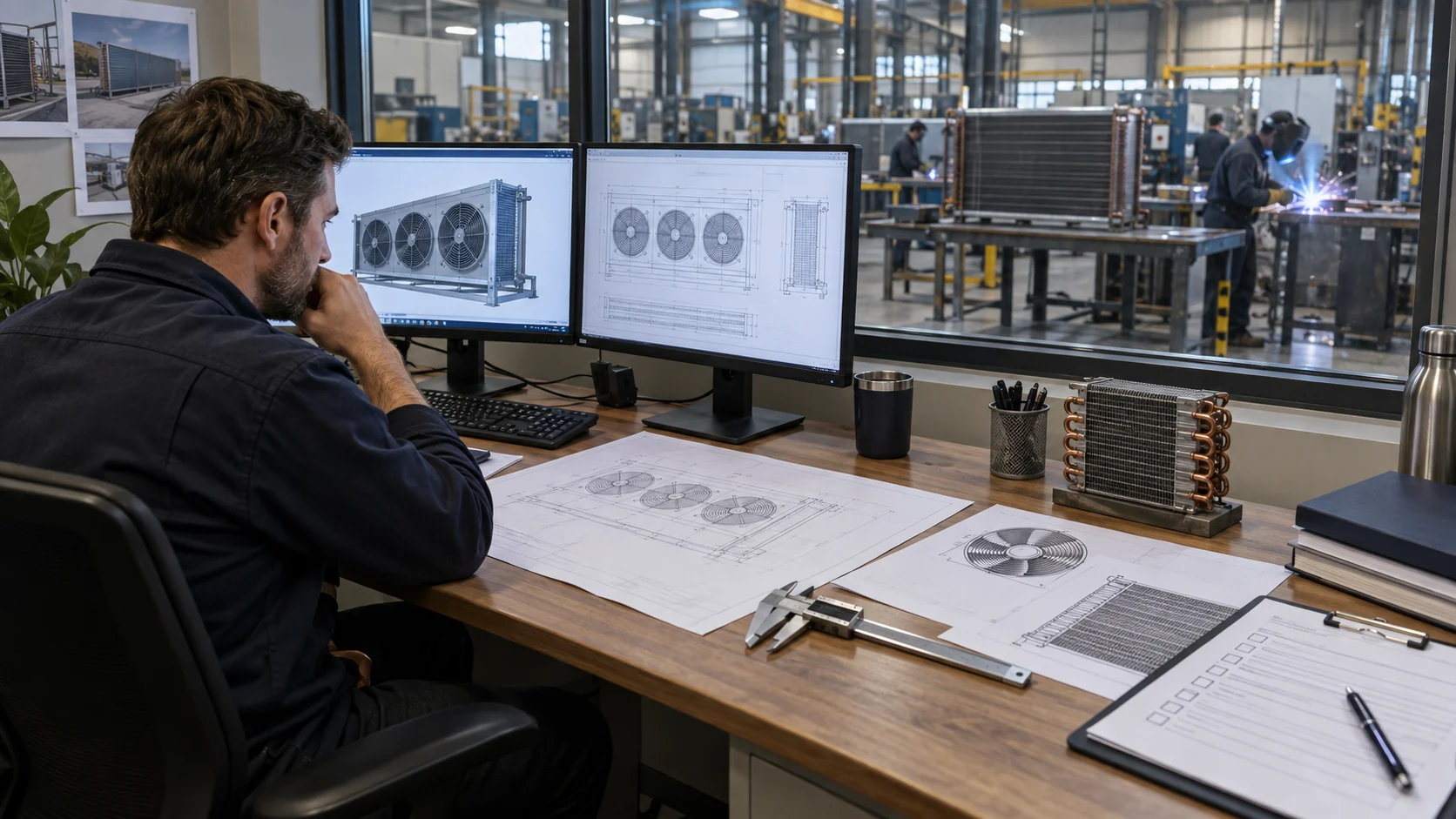
The practical workflow is: confirm the application; screen the heat-rejection method; review the preliminary selection; check materials and service access; approve the drawing; inspect and test the build; then preserve the final data for replacement and maintenance. Keep the approved drawing, inspection record, and serial or batch traceability with the equipment file.

Frequently asked questions
What is a condenser in refrigeration?
A condenser is the heat exchanger that rejects heat from high-pressure refrigerant vapor and changes it into high-pressure liquid, usually using air, water, or evaporative heat rejection. It sits between the compressor discharge and the expansion device.
What are the main types of condensers?
For industrial refrigeration, the main heat-rejection families are air-cooled, water-cooled, evaporative, and hybrid or remote arrangements. Common construction formats include fin-and-tube coils, shell-and-tube exchangers, plate exchangers, and microchannel coils.
Is an air-cooled or water-cooled condenser better?
Neither is universally better. Air-cooled equipment avoids a water loop but follows ambient conditions and needs airflow and coil cleaning. Water-cooled equipment can use a stable water condition but requires suitable flow, treatment, filtration, and water-side maintenance.
When should an industrial buyer choose an evaporative condenser?
Consider evaporative heat rejection when a compact outdoor package and strong heat rejection are important, and the site can manage water treatment, drift, plume, cleaning, winter operation, and local water requirements. Confirm the complete operating and maintenance plan before approval.
What information should I send for a condenser quote?
Send the refrigerant, duty or mass flow, design ambient or entering-water temperatures, condensing and subcooling targets, pressure-drop limits, materials, connection layout, controls, sound and footprint limits, quantity, delivery location, and required drawings or inspection documents.
How do condenser and evaporator coils differ?
A condenser rejects heat and changes refrigerant vapor toward liquid on the high-pressure side. An evaporator absorbs heat and boils liquid toward vapor on the low-pressure side. Their circuiting, design temperatures, fin spacing, controls, and service requirements therefore differ even when both use a finned coil.
Choose a condenser by the heat sink and service plan
For an OEM or replacement project, the most defensible choice is the one that matches the site heat sink, refrigerant duty, material exposure, service access, and documented test requirements. Domi’s related industrial refrigeration condenser coil selection guide and refrigeration condenser coil guide can help frame the coil-side discussion. Domi also provides engineering capabilities, testing information, and custom coil fabrication resources for buyers who need a drawing-led review. Send the duty, drawing, or replacement dimensions through the contact page to request a technical review and quote.