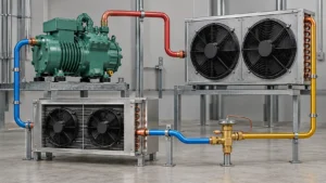
Refrigeration coil weld quality is the result of a controlled joint design, qualified joining process, suitable inspection plan, leak or pressure evidence where required, and traceability from material to production release. A smooth-looking bead alone does not prove that a header, return bend, accumulator, cap, or service connection will remain sound in the approved operating envelope. The drawing, customer specification, and applicable code must define the acceptance criteria.
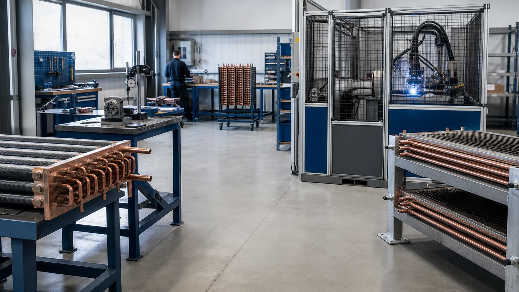
This guide is for OEM engineers, procurement managers, distributors, and quality teams who need to review a coil supplier’s joining evidence. It separates weld and braze decisions, fit-up controls, inspection methods, repair records, and the information needed before a component can be released. It does not assign a universal weld size, pressure, alloy, or test frequency. Those values belong to the approved design and governing requirements.
What good refrigeration coil weld quality means
A good joint answers four questions at the same time:
- Was the joint made to the correct drawing revision and joining procedure?
- Does the joint meet the specified visual, dimensional, surface, or volumetric acceptance criteria?
- Does the completed pressure boundary pass the required leak or pressure test without an unexplained deviation?
- Can the supplier connect the result to the material lot, operator or station, inspection record, and final release decision?
The answer changes with the coil construction. A stainless header may use a qualified fusion weld. A copper tube connection may use brazing. A small aluminum assembly may use a controlled brazing or welding process that is sensitive to oxide, heat input, and distortion. Treating every joint as the same weld creates a weak inspection plan.
The ASME BPVC catalog lists Section IX for welding, brazing, and fusing qualifications. AWS B2.1/B2.1M:2026 covers qualification of welding procedures, welders, and operators, including base metals, filler metals, variables, and testing. These references do not replace the code or customer specification selected for a particular coil. They show why a buyer should request the governing basis instead of accepting the word “certified” without scope.
Which coil joints need a quality review
Start with the pressure boundary, then include joints that can transfer vibration or thermal movement into that boundary. Mark each location on the latest drawing before asking for a supplier report.
| Joint or area | Typical risk | Review question | Useful evidence |
|---|---|---|---|
| Header to tube | Lack of fusion, incomplete penetration, local distortion | Is the joint geometry compatible with the approved process? | Fit-up record, visual inspection, procedure reference |
| Return bend or U-bend | Crack, thinning, misalignment, residual stress | Was the bend formed and joined without overstressing the tube? | Dimensional check, joint map, leak result |
| Distributor, accumulator, or branch | Congested geometry and difficult access | Can the complete circumference be inspected and tested? | Drawing location, inspection method, pressure or leak record |
| Cap, plug, or service connection | Hidden leak path or poor rework | Is the closure part of the test boundary? | Boundary mark-up, test record, deviation log |
| Mounting bracket near a header | Vibration or thermal load transferred to a joint | Is the support located and finished as shown? | Fixture check, visual record, final dimensional report |
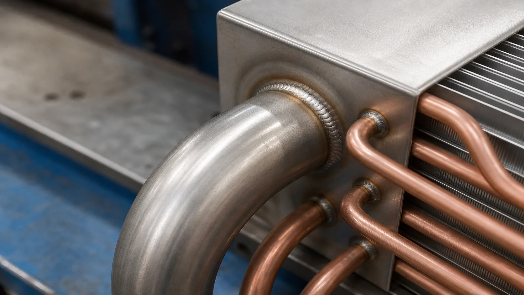
This map prevents a common mistake: inspecting the most visible joint while leaving a capped branch, plug, or accessory connection outside the evidence boundary. The article on evaporator coil leak diagnosis is useful when the problem is an in-service leak. This article focuses on how a supplier controls and proves the joint before shipment.
Weld or braze: make the decision from the design
Welding and brazing are joining methods, not quality grades. The correct choice depends on base materials, wall thickness, pressure and temperature, service fluid, joint access, heat input, corrosion exposure, repair policy, and the governing design rules.
| Decision field | Fusion weld | Brazed joint | Buyer action |
|---|---|---|---|
| Joint mechanism | Base material and filler are joined by fusion | Filler melts and wets the prepared surfaces without melting the parent parts in the same way | Name the process on the drawing or specification |
| Common concern | Heat-affected zone, penetration, distortion, and metallurgical change | Surface preparation, joint clearance, filler wetting, flux or purge control | Ask what process variables are controlled |
| Inspection emphasis | Bead profile, fusion, cracks, undercut, porosity, and procedure qualification | Wetting, continuity, filler distribution, oxidation control, and leak integrity | Match inspection to the actual failure mode |
| Repair question | Can the area be removed and re-welded under an approved procedure? | Can the joint be reheated without damaging nearby tubes or fins? | Require a repair route before production |
| Release evidence | WPS or equivalent, operator qualification where required, inspection and test record | Brazing procedure or work instruction, operator control, inspection and test record | Record revision, operator or station, and acceptance basis |
The AWS standard welding procedure specification resource explains that procedure specifications are supported by qualification records and tied to defined materials, processes, and application codes. A supplier does not need to send every proprietary document, but the buyer should know which approved procedure and acceptance rule govern the joint.
Control fit-up before the torch or arc starts
Most joint problems become more expensive after the parts have been heated. Fit-up is the last low-cost opportunity to catch a wrong tube, a poor gap, a misaligned header, a contaminated surface, or a fixture that forces the assembly into position.
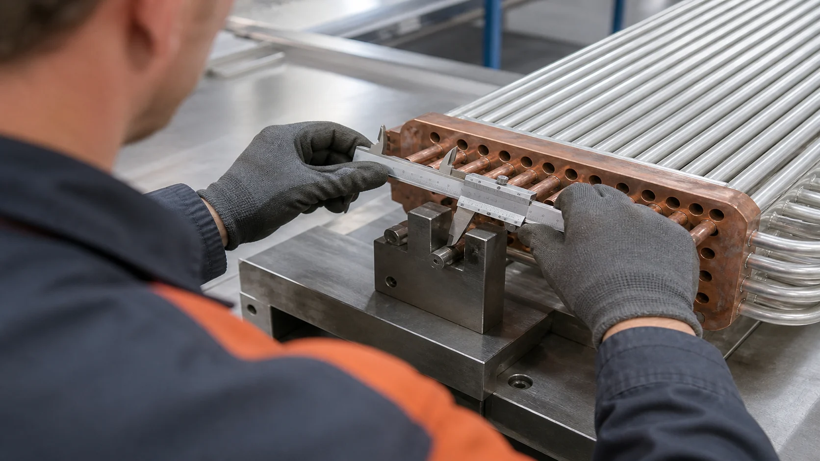
The supplier’s fit-up check should identify:
- drawing revision and part number;
- base material and thickness or tube specification;
- joint preparation and orientation;
- alignment, root opening, insertion depth, or overlap as applicable;
- cleanliness and removal of oil, oxide, coating, or burrs;
- fixture identification and any controlled preheat or purge setup;
- operator or station identification;
- disposition of a joint that falls outside the approved range.
Do not turn a supplier’s internal fit-up value into a universal requirement. The value must come from the drawing, qualified procedure, or customer specification. If the supplier proposes an equivalent material or joint detail, route it through engineering review and revision control before production uses it.
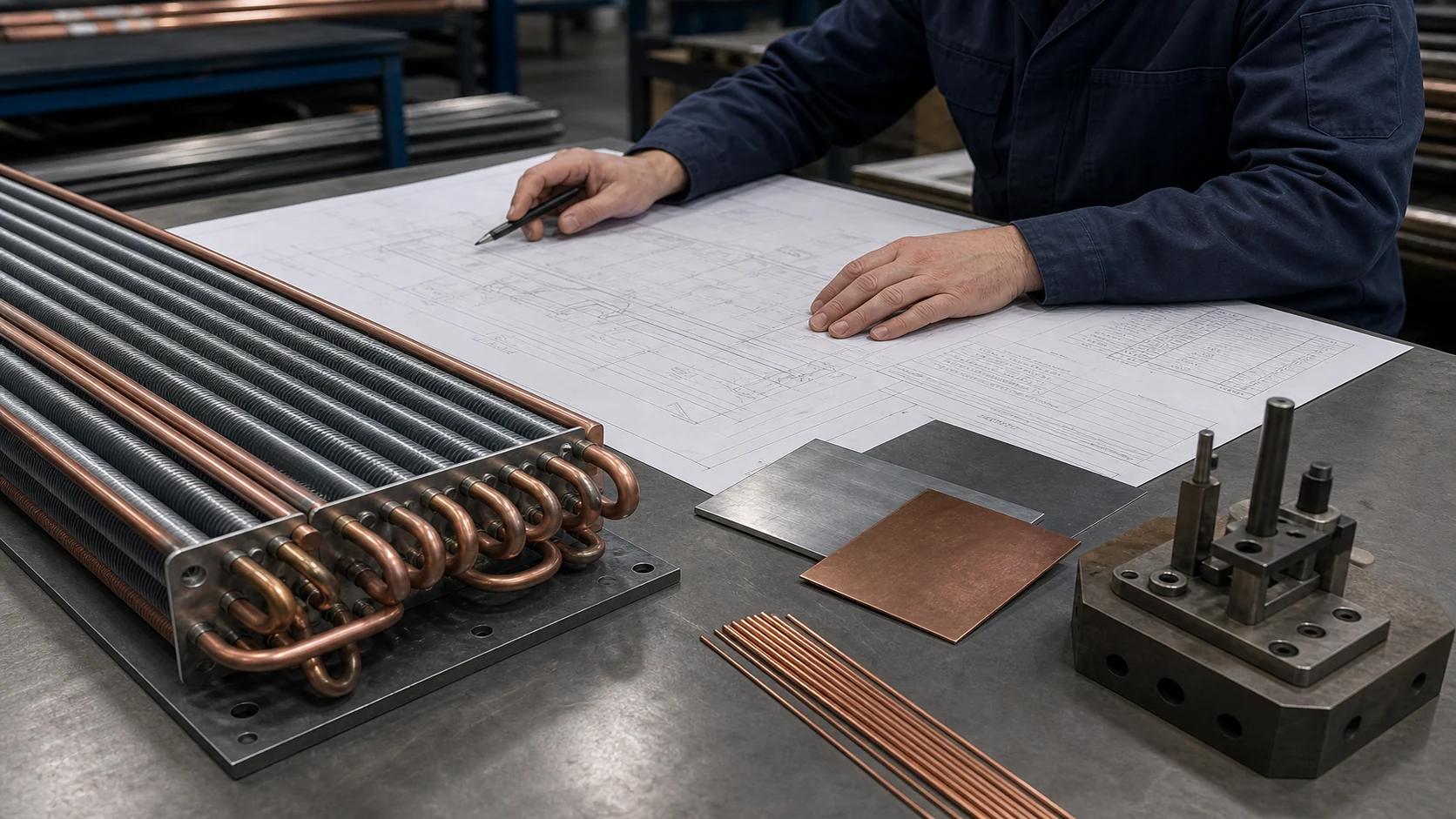
The OEM coil production part approval process explains why a joining change can be a controlled production change rather than a shop-floor adjustment. A change in filler, heat input, fixture, joint detail, or repair method may change the evidence package that supports release.
Control the joining process, not just the final appearance
Process control starts with a qualified procedure or a customer-approved work instruction. It should define the variables that can change joint integrity, such as material family, filler, torch or electrode, shielding or purge gas, current or heat input, travel speed, position, preheat, interpass control, cleaning, and sequence. The exact variables depend on the process and code.
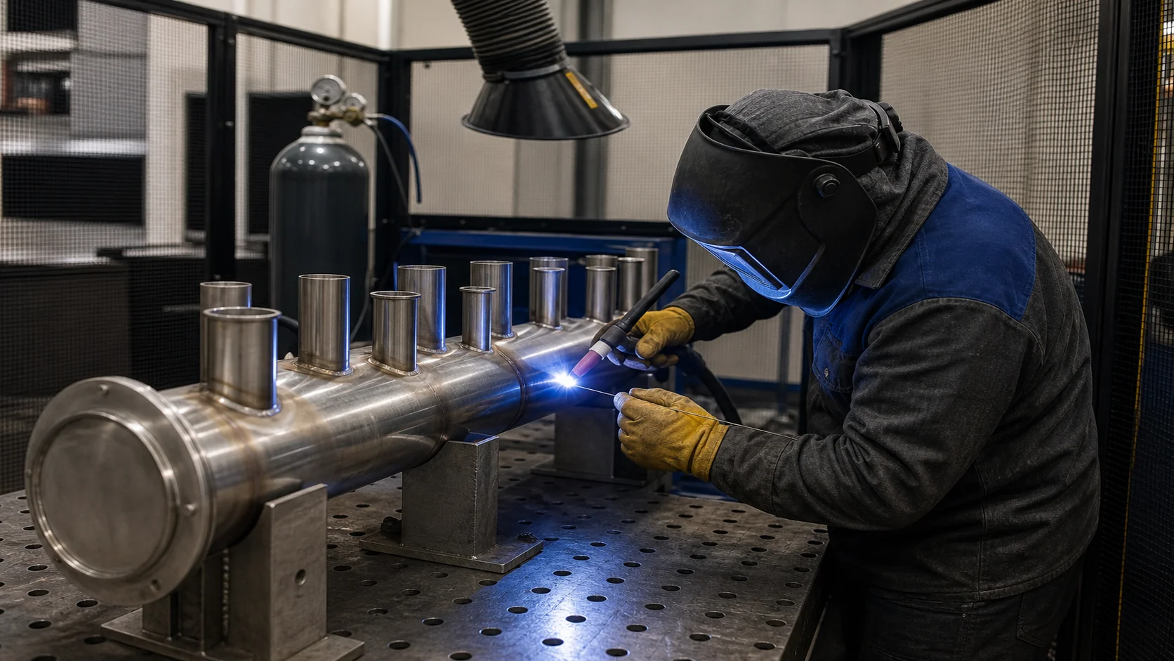
For brazed connections, add surface preparation, joint clearance, filler placement, heating pattern, flux or purge control, and post-braze cleaning where applicable. For welded headers, pay attention to access, penetration, distortion, crater treatment, and heat-affected areas near thin tube walls. Keep the work area clean enough that the joint is not hiding oil, scale, flux, or grinding residue.
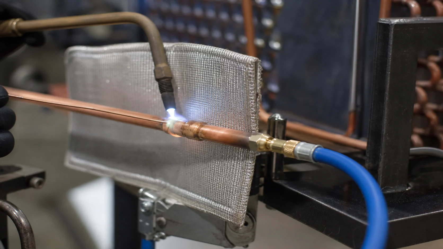
The AWS codes and standards page notes that welding requirements are developed for defined applications and that a competent engineer should address problems outside a standard’s scope. That is a useful procurement rule: request the applicable document and scope, not a generic statement that the factory follows welding standards.
Use an inspection ladder that matches the risk
No single inspection method proves every aspect of a joint. A practical plan moves from low-cost checks to targeted tests, with the acceptance criteria written before the result is reviewed.
| Inspection stage | What it can show | What it cannot prove by itself | Record to request |
|---|---|---|---|
| Visual and dimensional | Bead profile, alignment, burn-through, undercut, surface damage, location, and finished geometry | Internal discontinuities or long-term service performance | Signed checklist, photos, drawing revision |
| Surface examination | Surface-breaking indications where the method is suitable for the material and finish | Defects below the inspected surface or a complete pressure boundary | Method, area, examiner, result, acceptance rule |
| Volumetric examination | Selected internal indications when the method, thickness, access, and material support it | Leak tightness of every path or thermal performance | Technique, coverage, calibration, images or report |
| Leak or pressure test | Boundary integrity under the specified test setup and conditions | Weld procedure qualification or fatigue life outside the test | Test boundary, medium, pressure or limit, hold, instrument, result |
| Cleanliness and functional check | Residue, blockage, connection condition, and installation readiness | Structural acceptance of the joint | Cleaning record, final inspection, release sign-off |
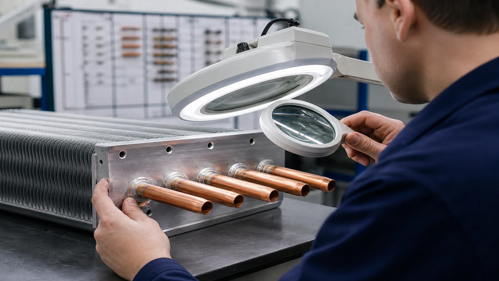
Choose non-destructive testing only when it answers a defined risk. Radiography, ultrasonic testing, dye penetrant, magnetic particle, eddy current, or another method may be appropriate in some designs and unsuitable in others. The article should never imply that every coil needs every method. Ask the supplier to state why the selected method can detect the specified defect type in the actual material and geometry.
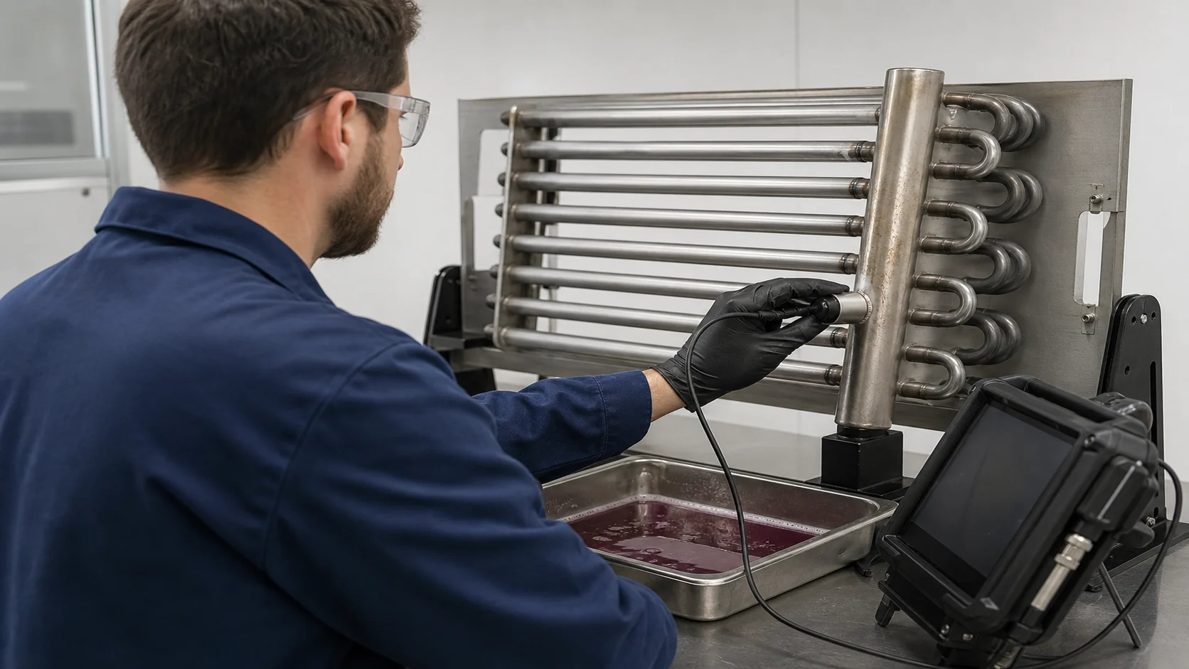
Read the leak and pressure record as a boundary document
The pressure or leak record should identify what was tested, not only whether a box was checked. Confirm the boundary drawing, isolated circuits, caps and plugs, test medium, test sequence, instrument identity, calibration status, start and end conditions, acceptance criterion, operator, date, and disposition of any abnormal result.
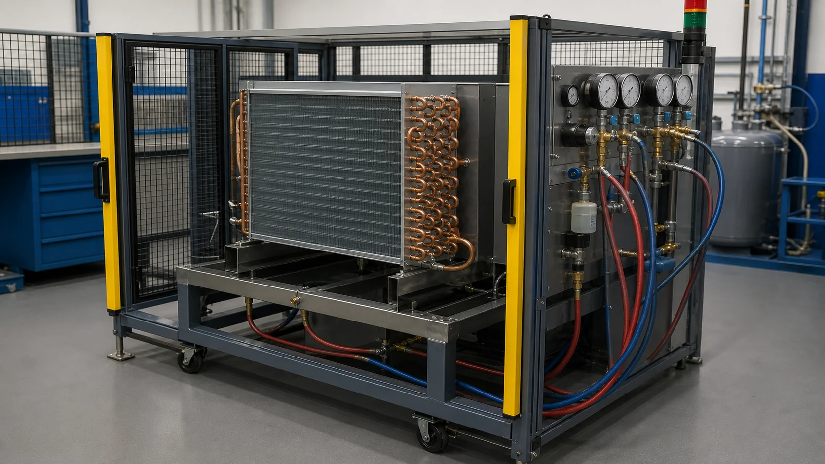
For a coil with several circuits, check whether the record covers them all. A test on one circuit does not automatically prove an unconnected branch or accessory. A supplier may use a separate leak test, proof test, or destructive qualification test. Keep those purposes distinct. The CO2 coil burst pressure testing guide gives a separate explanation of proof, working, leak, and burst evidence for high-pressure CO2 projects.
Require traceability that follows the joint
Traceability should still work after a coil is moved from fabrication to inspection, packing, and service records. It does not require a large software system. It requires a stable identifier and a controlled handoff.
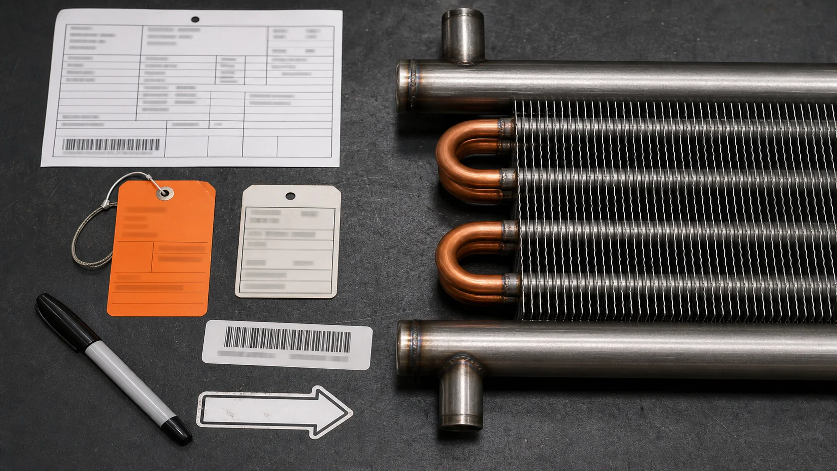
A useful traceability chain connects:
- coil part number, drawing revision, and serial or batch;
- tube, header, filler, and other pressure-boundary material lots;
- joining procedure revision and operator or station;
- joint location map or inspection reference;
- visual, NDT, leak, pressure, and dimensional records;
- repair, deviation, concession, and re-inspection decisions;
- final quality release and shipment record.
The custom refrigeration coil RFQ checklist can help a buyer collect the drawing, sample, connections, materials, quantity, and inspection expectations before quotation. Add the traceability fields to the RFQ when a joint is safety-critical or difficult to inspect after installation.
Control repairs and deviations as new evidence
Grinding, polishing, reheating, plugging, or adding filler can change the original joint. A repair should therefore have a reason, approved method, responsible person, and re-inspection route. Do not erase the initial failure from the record. Keep the original result, identify the repaired location, and link the new inspection to the same part and revision.
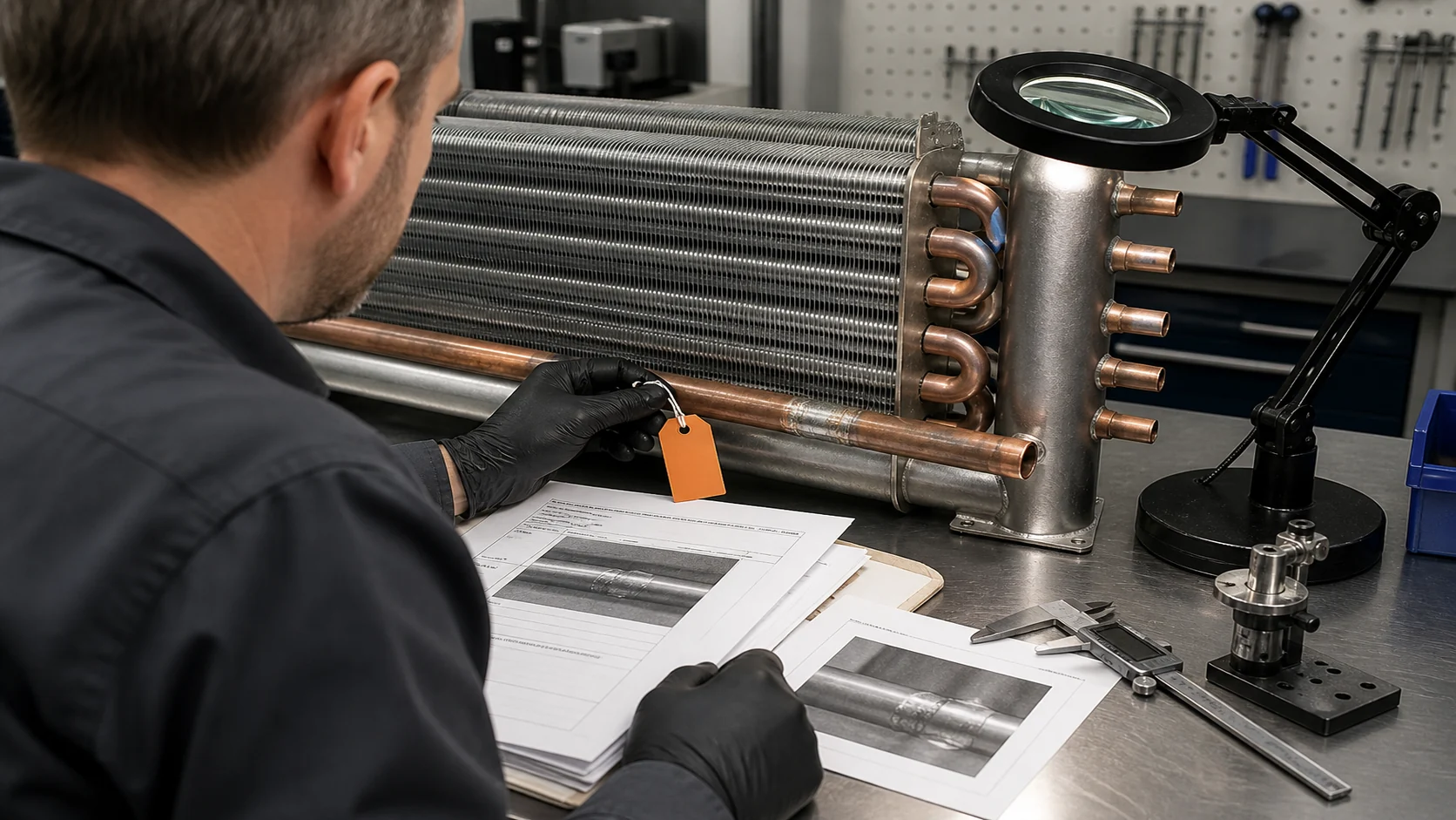
Ask these questions when a report contains a repair or concession:
- Was the repair allowed by the drawing, procedure, code, or customer specification?
- Did the repair change material, filler, heat input, joint geometry, or test boundary?
- Was the repaired area re-inspected using a method that can find the original defect?
- Was the complete coil retested when the repair could affect the pressure boundary?
- Who accepted the deviation, and where is the approval stored?
Repeated repairs in the same location are a process signal. The right response may be fixture correction, a procedure review, a material change, or a design change. It is not always another cosmetic pass over the bead.
What a buyer should request before production release
The final release package should let an engineer answer what was built, how it was joined, how it was inspected, and what remains open. A report that only says “passed” leaves too much of the decision to memory.
| Release item | Minimum useful content | Why it matters |
|---|---|---|
| Drawing and configuration | Part number, revision, joint map, circuit or boundary definition | Establishes what the evidence belongs to |
| Process evidence | Joining procedure revision, material and filler, operator or station, controlled variables | Shows how the joint was made |
| Inspection evidence | Visual, dimensional, NDT, leak, or pressure records as required | Connects the acceptance decision to a method |
| Deviation and repair record | Original result, repair method, re-inspection, approval | Prevents hidden rework from becoming a shipment assumption |
| Final release | Named reviewer, date, open items, packaging and shipment status | Shows who accepted the configuration and what leaves the factory |
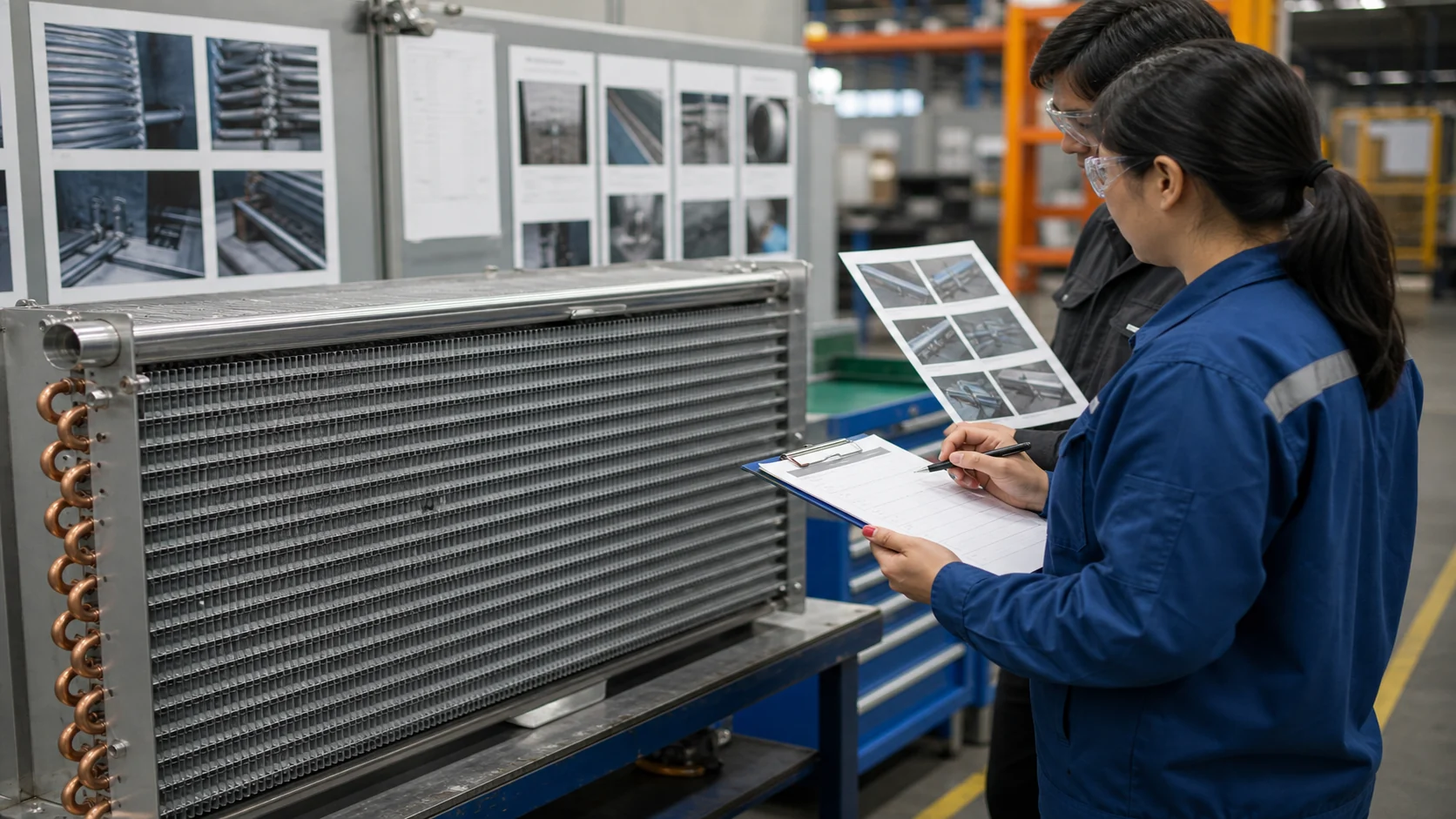
If the project involves a regulated pressure boundary, ask the responsible engineer to identify the governing code and required certification route. A supplier may provide a test report or material certificate without being authorized to make a code compliance claim for the complete system. Keep supplier evidence, customer approval, and final system certification as separate decisions.
Build the RFQ around the joint risk
Send more than a keyword such as “welded coil.” Attach the drawing or sample photos, fluid, operating and design conditions, pressure or test requirements, material restrictions, connection layout, joint locations, environment, inspection plan, quantity ladder, packaging, destination, and requested dates. If the design is not fixed, identify which choices are open to supplier proposal.
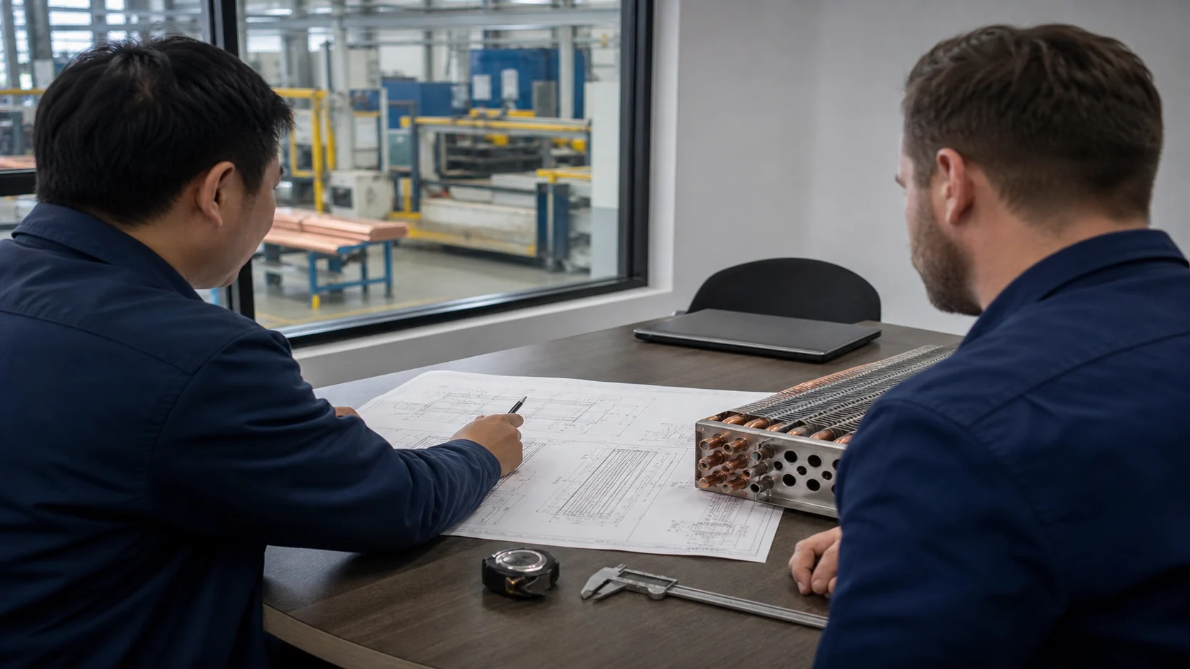
For a new or revised assembly, ask the supplier to return an assumption register, a proposed joining route, a joint and inspection map, a sample plan, and a list of open questions. Domi’s thermal engineering and CFD page is a relevant starting point when the drawing needs technical review. The testing lab page is the better inquiry destination when the project needs a defined inspection or validation conversation.
Frequently asked questions
What inspection methods are used to check refrigeration coil weld quality?
Start with visual and dimensional inspection, then add surface, volumetric, leak, or pressure testing when the joint risk and governing requirements justify it. The supplier should name the method, coverage, acceptance rule, examiner or operator, and record. A test method is useful only when it can detect the defect type that matters in the actual material and geometry.
How do you verify leak and pressure resistance in a coil joint?
Define the complete test boundary first, including circuits, headers, caps, plugs, and accessories. Then record the specified medium, test conditions, instrument identity, hold or observation period, acceptance criterion, and result. Do not treat one circuit or one joint as proof of an untested boundary.
What traceability should a coil supplier provide?
The record should connect the part and drawing revision to material lots, joining procedure, operator or station, joint location, inspection results, repair history, and final release. The format can be a traveler, digital record, or controlled report. The important point is that another reviewer can follow the chain without guessing.
How should a supplier control a repaired weld or braze?
Keep the original nonconformance, identify the repair method and responsible approval, and repeat the inspection that addresses the original risk. If the repair changes the pressure boundary or procedure, review whether the whole coil needs another leak or pressure test. A repaired joint should never disappear into a new clean-looking photograph.
What evidence demonstrates joint quality without overclaiming compliance?
Request the approved drawing and procedure reference, material and filler information, inspection reports, test records, calibration or instrument references, traceability identifiers, repair or deviation records, and final release sign-off. Ask the supplier to state the exact code or customer specification used. Do not accept a general certification claim when the scope is unclear.
When can a welded or brazed coil be released to production?
Release follows completion of the required configuration, process, inspection, test, and documentation checks. The responsible quality or engineering authority should close open deviations and confirm that the shipped part matches the tested revision. Production release is a controlled decision, not a visual opinion about a bead.
Turn weld evidence into an approval decision
The most useful refrigeration coil weld quality review is short enough to use at the quotation desk and detailed enough to survive a design change. Define the pressure boundary, select the joining process from the design, qualify and control the process, inspect the right locations, preserve traceability, and close repairs before release. When you send a drawing or sample to a supplier, ask for the proposed joint map and evidence package with the quotation. That turns a vague quality request into an engineering decision.